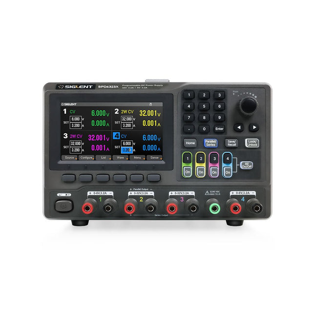
The Siglent SPD4323X is a 4-channel DC Linear Programmable Power Supply equipped with a 4.3-inch TFT-LCD display, friendly human-machine interface, and excellent performance indicators. Real-time waveform display provides engineers with an informative user interface.
SPD4323X offers a total output power of 240 W with a resolution of 1 mV/1 mA. The maximum voltage and current for each channel are as follows:
CH1: 6 V/3.2 A
CH2: 32 V/3.2 A
CH3: 32 V/3.2 A
CH4: 6 V/3.2 A
Features
Rated output power: 240 W
Rated voltage: 32 V, 12 V, 30 V
Up to four high-precision power supplies with independent controllable outputs, supporting CH2 and CH3 series and parallel connections
Clear graphical interface with waveform and timer display modes
5-digit voltage and current display with minimum resolution of 1 mV, 1 mA
Fast output response time: <50us
The high current channel support remote voltage compensation sense function. The maximum compensation voltage is 0.6 V
Overvoltage protection and overcurrent protection or safe and accurate operation
Equipped with a 4.3-inch TFT-LCD display (480 x 272 resolution)
USB and LAN standard communication
USB-GPIB module is optional
Excellent channel density with up to 4 channels in a 3U half rack package
Internal data storage for setups and parameters
Embedded Web Server with instrument communication that doesn’t require software installation
Fully SCPI programming command set support as well as a LabView driver for remote control and system automation
Specifications
SPD4323X
SPD4121X
SPD4306X
Channel Output
CH1: Voltage 0 to 6 V Current 0 to 3.2 ACH2: Voltage 0 to 32 V Current 0 to 3.2 ACH3: Voltage 0 to 32 V Current 0 to 3.2 ACH4: Voltage 0 to 6 V Current 0 to 3.2 A
CH1: Voltage 0 to 15 V Current 0 to 1.5 ACH2: Voltage 0 to 12 V Current 0 to 10 ACH3: Voltage 0 to 12 V Current 0 to 10 ACH4: Voltage 0 to 15 V Current 0 to 1.5 A
CH1: Voltage 0 to 15 V Current 0 to 1.5 ACH2: Voltage 0 to 30 V Current 0 to 6 ACH3: Voltage 0 to 30 V Current 0 to 6 ACH4: Voltage 0 to 15 V Current 0 to 1 A
Resolution
1 mV, 1 mA
1 mV, 1 mA
1 mV, 1 mA
Setting Accuracy
Voltage: ±(0.03% of reading+10) mV, Current: ±(0.3% of reading+10) mA
Voltage: ±(0.03% of reading+10) mV, Current: ±(0.3% of reading+10) mA
Voltage: ±(0.03% of reading+10) mV, Current: ±(0.3% of reading+10) mA
Readback Accuracy
Voltage: ±(0.03% of reading+10) mV, Current: ±(0.3% of reading+10) mA
Voltage: ±(0.03% of reading+10) mV, Current: ±(0.3% of reading+10) mA
Voltage: ±(0.03% of reading+10) mV, Current: ±(0.3% of reading+10) mA
Display
4.3" TFT-LCD 5-digit voltage and current display
4.3" TFT-LCD 5-digit voltage and current display
4.3" TFT-LCD 5-digit voltage and current display
Output power
240 W
285 W
400 W
Included
1x Siglent SPD4323X Power Supply
1x Power cord (EU)
1x Output test cord (3 A)
1x USB cable
1x Quick start guide
Downloads
Datasheet
Manual
Quick start
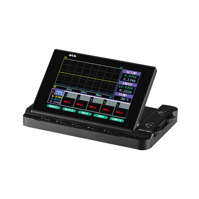
MDP-M01 is a display control module equipped with a 2.8-inch TFT display screen, the screen can be turned 90 degrees, which is convenient for users to view data and waveform. MDP-M01 can realize online display and control with MDP-P906 mini digital power supply modules and other modules of MDP system through 2.4 GHz wireless communication, and can control up to 6 sub-modules at the same time.
Specifications
Screen size
2.8" TFT
Screen resolution
240 x 320
Power
Micro USB power input, or taking power from sub-module via dedicated power cable
Input
DC 5 V/0.3 A
Other functions
Can control up to 6 sub-modulesUpgrade firmware through Micro USB
Dimensions
107 x 66 x 13.6 mm
Weight
133 g
Included
1x MDP-M01 Smart Digital Monitor
1x Cable (2.5 mm jack to Micro USB)
Downloads
User Manual v3.4
Firmware v1.32
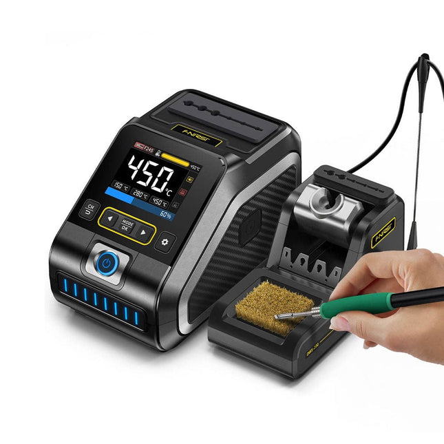
The FNIRSI DWS-200 is a powerful 200 W smart soldering station, ideal for electronic soldering applications. Powered by a switch-mode power supply, it operates smoothly with a wide voltage input range of 100-240 V. The station provides an adjustable temperature range from 100°C to 450°C (212°F to 842°F) and allows for easy switching between °C and °F.
To enhance efficiency, it supports up to three preset temperature values and can connect to a soldering iron stand for standby mode activation. The station also features a dynamic temperature curve mode for real-time data monitoring, ensuring precise and consistent performance in demanding soldering tasks.
Features
Maximum power output of 200 W, allowing for fast heating
Wide adaptive voltage input of 100-240 V
2.8" HD color TFT display with intelligent control
Multiple preset groups to switch between different settings quickly
Supports F245 and F210 soldering handle types, offering flexibility for different soldering applications
Real-time sleep mode to extend the life of the soldering tip
Multi-mode real-time monitoring for power and temperature status, enhancing safety and precision
Specifications
Peak Power
200 W (max)
Temperature Range
100°C~450°C (212°F~842°F)
Display
2.8" TFT HD Color Screen
Heating Time
1 sec
Melting Time
3 sec
Input Voltage
100-240 V (AC)
Input Fuse
3 A
Soldering Handle Type
F245
Dimensions (Station)
156 x 96 x 103 mm
Weight (Station)
475 g
Included
1x FNIRSI DWS-200 Soldering Station
1x Soldering Handle F245
6x Soldering Tips (B, KU, K, C2, I, JS)
1x Connecting Cable
2x Helping Hands
1x Power Cable (EU)
Downloads
Manual
Firmware V1.3
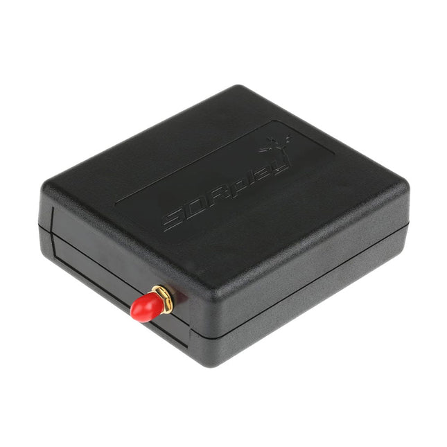
The SDRplay RSP1B is an enhanced version of the popular RSP1A – a powerful, wideband, full-featured 14-bit SDR that covers the RF spectrum from 1 kHz to 2 GHz. The RSP1B comes in a rugged, black-painted steel case and offers significantly improved noise performance.
All it needs is a computer and an antenna to deliver excellent communications-receiver functionality. It includes a choice of SDRuno for Windows and the multi-platform SDRconnect software for Windows, macOS, and Linux (supplied free of charge by SDRplay). You can monitor up to 10 MHz of spectrum at a time.
A documented API allows developers to create new demodulators or applications for the platform.
Features
Covers all frequencies from 1 kHz through VLF, LF, MW, HF, VHF, UHF and L-band to 2 GHz, with no gaps
Receive, monitor and record up to 10 MHz of spectrum at a time
Free use of windows-based SDRuno software which provides an ever-increasing feature-set
Strong and growing software support network
Calibrated S meter/ RF power and SNR measurement with SDRuno (including datalogging to .CSV file capability)
Documented API provided to allow demodulator or application development on multiple platforms
Excellent dynamic range for challenging reception conditions
Works with popular 3rd party SDR software (including HDSDR, SDR Console and Cubic SDR)
ExtIO based plugin available
Software upgradeable for future standards
Strong and growing software support network
API provided to allow demodulator or application development
Multiplatform driver and API support including Windows, Linux, Mac, Android and Raspberry Pi
Up to 16 individual receivers in any 10 MHz slice of spectrum using SDRuno
Calibrated S meter and power measurements with SDRuno
Stand-alone windows-based spectrum analyser software available (with sweep, sample and hold features)
Ideal for monitoring of ISM/ IoT/ Telemetry bands <2 GHz
Ideal for portable operation
Specifications
Frequency Range
1 kHz – 2 GHz
Antenna Connector
SMA
Antenna Impedance
50 Ohms
Current Consumption (Typical)
185 mA (excl. Bias-T)
USB Connector
USB Type B
Maximum Input Power
+0 dBm Continuous+10 dBm Short Duration
ADC Sample Rates
2-10.66 MSPS
ADC Number of Bits
14 bit 2-6.048 MSPS12 bit 6.048-8.064 MSPS10 bit 8.064-9.216 MSPS8 bit >9.216 MSPS
Bias-T
4.7 V100 mA guaranteed
Reference
0.5ppm 24 MHz TCXO.Frequency error trimmable to 0.01ppm in field.
Operating Temperature Range
-10˚C to +60˚C
Dimensions
98 x 88 x 34 mm
Weight
110 g
Downloads
Datasheet
Software
RSP1B vs RSPdx vs RSPduo
RSP1B
RSPdx
RSPduo
Continuous coverage from 1 kHz to 2 GHz
✓
✓
✓
Up to 10 Mhz visible bandwidth
✓
✓
✓
14-bit ADC silicon technology plus multiple high-performance input filters
✓
✓
✓
Software selectable AM/FM & DAB broadcast band notch filters
✓
✓
✓
4.7 V Bias-T for powering external remote antenna amplifier
✓
✓
✓
Powers over the USB cable with a simple type B socket
✓
✓
✓
50Ω SMA antenna input(s) for 1 kHz to 2 GHz operation (software selectable)
1
2
2
Additional software selectable Hi-Z input for up to 30 Mhz operation
✓
Additional software selectable 50Ω BNC input for up to 200 MHz operation
✓
Additional LF/VLF filter for below 500 kHz
✓
24 MHz reference clock input (+ output on RSPduo)
✓
✓
Dual tuners enabling reception on 2 totally independent 2 MHz ranges
✓
Dual tuners enabling diversity reception using SDRuno
✓
Robust and strong plastic case (with internal RF shielding layer)
✓
Rugged black painted steel case
✓
✓
Overall performance below 2 MHz for MW and LF
+
++
+
Multiple simultaneous applications
+
+
++
Performance in challenging fading conditions (*using diversity tuning)
+
+
*++
Practical Projects and Programs
With Experimenting with Red Pitaya STEMlab Gen 2, Red Pitaya goes beyond a versatile board. It becomes a powerful laboratory instrument for precision measurement, analysis, and control.
From the fundamentals of electronic project development, monitoring, control, and design to testing, this book walks you step-by-step through everything you need to know to harness the full potential of Red Pitaya hardware and software.
The book presents real-time, FPGA-based projects that are developed on a PC using the Vivado environment, then transferred to the Red Pitaya for execution and testing.
You will learn about enhanced performance, expanded I/O capabilities, improved FPGA features, and advanced connectivity options that open up new frontiers for precision measurement, monitoring, and control in your embedded applications.
Inside the book you will discover:
A deep dive into Red Pitaya architecture and hardware design
Electronic experiments using Red Pitaya for measurement and monitoring
Hands-on projects using the Python programming language
Practical guidance for FPGA programming using Red Pitaya
Red Pitaya FPGA projects using the Verilog HDL under Vivado IDE
Practical design of electronic projects including measurement and testing
Step-by-step examples that bridge theory and real-world implementation
Whether you are designing your own electronic circuits, developing signal analysis tools, or creating real-time control or monitoring systems, this book provides you the knowledge and confidence you need to fully learn and customize the Red Pitaya platform.
Electronic devices increasingly come with glued displays and batteries. And while the adhesive seal serves as a protection against dirt and water, it complicates the opening procedure of the device and hence its repair.
The iOpener: Warm it through, unstick the glue!
With the help of our iOpener, you can easily and quickly loosen adhesive without risking damage to your device due to overheating with a heat gun. Originally designed for opening Apple iPads, the iOpener is just as suitable for Samsung tablets, Sony smartphones, and devices from any other manufacturer who prefers adhesive over screws.
How it works
Heat the iOpener and place it on your device: Simply heat up the iOpener in the microwave or a pot of boiling water and position it on the edge of your device. The heat will soften the adhesive without damaging your gadget so you can insert an opening pick between the display and the case. Repeat this procedure for all glued areas, the iOpener is reusable any number of times.
Use opening tools to remove adhesive residue: With the right tools, you’re now ready to open your device without hassle. The opening picks are sharp-edged enough to cut through the adhesive strips. Complete the opening procedure by prying up the case with an opening tool or lift your display with a suction cup or an iSclack.
A must-have for electronic repairs
The most annoying part of your repair is done, the rest will be almost a cinch. Whether you are a beginner or a professional, the iOpener should be part and parcel of every toolbox worthy of its name.
Your advantages
Loosen adhesive fastenings
Uncomplicated to heat up in the microwave or boiling water
Reusable
Optionally available with opening tools
Contains food grade glycerine
Saves money and the planet
Included
iOpener
Spudger
iFixit Opening Tool
6x iFixit Opening Picks
iFixit Battery Isolation Pick
Plastic Cards
Suction Cup
Angled Tweezers
Plastic bit driver with magnetic bit socket (4 mm), rubberized handle and swivel cap
Precision bits (4 mm)
Phillips #00
Flathead 2.5 mm
The Weller WT 1013 soldering station set includes the WT 1 supply unit, the WP 80 soldering iron and the WSR 201 safety rest. It is stackable and thus creates more space in the workplace. With an integrated usage sensor, the soldering tool switches off automatically.
Specifications
Channels
1
Voltage
230 V
Power
95 W
Display
Backlit LCD
Temperature range
50 °C - 450 °C
Temperature stability
±2 °C
Temperature accuracy
±9 °C
Fuse
0.5 A
Equipotential bonding
on
WT compatible
on
ESD-safe
on
Power cable
EMEA
Dimensions
149 x 138 x 101 mm
Weight (approx.)
1.9 kg
En moins de 100 lignes de code par projet avec les cartes Feather Sense et Clue Express d'Adafruit
Le langage de programmation Python est apprécié par les pédagogues parce que sa syntaxe le rend facile à comprendre. Il s'est également imposé chez les informaticiens expérimentés. La société Adafruit a développé une version spéciale de Python pour l'embarquer sur les microcontrôleurs à 32 bits : CircuitPython.
Ce livre permettra au lecteur de s'initier à la programmation en CircuitPython sur deux cartes : Feather BlueFruit Sense (également appelée Feather nRF52840 Sense) et CLUE nRF52840 Express. Chacune est animée par le SoC nRF52840 de NORDIC avec une architecture à 32 bits.
Pour ce voyage dans le monde de la programmation embarquée, l'auteur sort du chemin classique, à savoir un cours complet sur la programmation orientée objet appliquée à ce langage. Il préfère emmener le lecteur directement sur le terrain avec des projets qui mettent en oeuvre les cartes et différents périphériques. Plus d'une quarantaine d'exemples et de montages permettent de découvrir la richesse de CircuitPython. Toutefois l'auteur s'est imposé une limite pour ne pas décourager les novices : le code de chaque projet ne dépasse jamais la centaine de lignes. Pour ce qui est du matériel, là aussi la simplicité domine : aucun programmateur, un simple PC suffit ; aucun soudage grâce au câblage sur platine d'essai. Les cartes d'extension FeatherWing à enficher sur la Feather nRF52840 Sense permettent de démultiplier ses fonctions : matrice de LED, enregistreur de données, écran à encre électronique, écran OLED, écran TFT, commande de moteurs, audio, relais…
Toutes les étapes (assemblage des différents composants, installation des bibliothèques requises, programmation, tests…) sont expliquées en détail. Le code des différents exemples et projets est disponible sur Github. Le résultat de chaque projet est même présenté sur de courtes vidéos disponibles sur YouTube.
À la fin de sa lecture, le nouveau Pythonien pourra facilement approfondir les notions abordées et donner vie à ses propres projets grâce aux outils qu'il aura essayés.
Ce livre s'adresse aux lycéens et étudiants ainsi qu'à toute la communauté des makers.
Chaîne YouTube de l'auteur :
YouTube (Michaël Bottin)
Drahtlose Kommunikation – sei es zur Ton-, Daten- oder Bildübertragung – prägt unser heutiges Leben. Während noch Mitte des letzten Jahrhunderts der Rundfunk (und etwas später das Fernsehen) die dominierenden Anwendungen der drahtlosen Kommunikation waren, gibt es heute kaum mehr ein technisches Gerät, das nicht das Mittel der drahtlosen Kommunikation nutzt. Allen voran das beliebte Smartphone.
Daneben gibt es sehr viele Anwendungen, die wir nicht sofort und automatisch mit den Begriffen Radio oder Funk verbinden, die aber auf der Nutzung elektromagnetischer Strahlung basieren. So zum Beispiel der Wagenschlüssel, die über Bluetooth verbundenen Kopfhörer, der automatische Rasenmäher, die gehassten Radargeschwindigkeitsmesser, der Laptop, der über Wi-Fi mit dem Internet verbunden ist, die kleinen Navigationsempfänger, usw.
Diesen Anwendungen gemeinsam ist die Nutzung physikalischer Gegebenheiten durch die Technik. Ob Radar, Satellitenfernsehen, oder einfach nur das alte Mittelwellenradio, alle bauen auf denselben Grundlagen auf.
Das Ziel dieses Buch ist es, diese Grundlagen zu erläutern und damit das Verständnis für die darauf aufbauenden Anwendungen zu fördern. Es soll Studenten den Einstieg ins Fachgebiet erleichtern und Voraussetzungen für den Zugang zu den Standardwerken der Fachliteratur schaffen. Es richtet sich aber auch an Personen, die an der Physik und der Technik interessiert sind und einen tieferen Einblick in die Grundlagen der drahtlosen Kommunikation und deren Anwendung erhalten wollen.
Beginselen van het programmeren Eenvoudige projecten voor beginners Interface- en hardware-uitbreidingen Complexe projecten voor gevorderden Twee zaken hebben in belangrijke mate bijgedragen aan het grote succes van het Arduinoplatform. De eerste is de complete, gebruiksklare processorprint die de kennismaking met dehardware aanzienlijk vergemakkelijkt. En de tweede is de gratis verkrijgbare programmeerinterface, die zonder ingewikkelde installatieprocedures meteen gebruikt kan worden. Eenvoudige projecten voor beginners garanderen snelle resultaten. Het is niet nodig eerst ingewikkelde parameters (processortype of interface-instellingen) te selecteren -- de eerste voorbeeldprogramma's kunnen al na enkele minuten in de Arduino worden geladen en uitgeprobeerd. De Arduino-gebruiker wordt geholpen door een groot aantal software-bibliotheken -- maar deze nog dagelijks groeiende schat aan libraries vormt juist voor de beginner een luxe-probleem: na de eerste eenvoudige voorbeelden is het niet altijd even duidelijk hoe het nu verder moet. Bij de in het internet circulerende projecten ontbreekt het in veel gevallen aan gedetailleerd commentaar en uitleg. Er is geen duidelijk herkenbare leidraad, en eigenlijk is dat ook niet zo vreemd omdat de toepassingen door verschillende mensen voor verschillende doeleinden zijn ontwikkeld. Dat is waar dit boek te hulp komt. Projecten worden op een systematische manier gepresenteerd, waarbij elk project een ander onderwerp belicht. De aanpak is praktijkgericht, maar de noodzakelijke theoretische achtergrond wordt daarbij niet uit het oog verloren. Belangrijke onderwerpen zoals A/D-omzetting, timers en interrupts worden steeds in praktische projecten 'ingebed'. In het boek komen zaken als looplicht-effecten, praktisch bruikbare voltmeters, nauwkeurige digitale thermometers, allerlei soorten klokken, reactietesters en zelfs een muisgestuurde robotkraan aan de orde. En al lezende en doende krijgt de lezer een gedegen inzicht in de achterliggende controllertechnieken.
Highlights
Output Frequency (Sine): 70 MHz
Output Frequency (Square): 20 MHz
Channels: 2
Arbitrary Waveform Length: 16 Mpts
Features
Unique SiFi II (Signal Fidelity II) technology: generate the arbitrary waveforms point by point; recover the signal without distortion; sample rate accurate and adjustable; jitter of all the output waveforms (including Sine, Pulse, etc.) as low as 200 ps
16 Mpts memory depth per channel for arbitrary waveforms
Standard dual-channel with the same performance, equivalent to two independent signal sources
High frequency stability: ±1 ppm; low phase noise: -105 dBc/Hz
Built-in high-order harmonic generator (at most 8-order harmonics)
Built-in 7 digits/s, 240 MHz bandwidth full featured frequency counter
Up to 160 built-in arbitrary waveforms, covering the common signals in engineering application, medical electronics, auto electronics, math processing, and other various fields
Sample rate up to 250 MSa/s, vertical resolution 16 bits
Arbitrary waveform sequence editing function available; arbitrary waveforms also can be generated through the PC software
Various analog and digital modulation functions: AM, FM, PM, ASK, FSK, PSK, and PWM.
Standard waveform combine function, capable of outputting specified waveforms combined with the basic waveforms
Standard channel tracking function, when enabled, all the parameters of both channels are updated based on users' configurations
Standard interface: USB Host&Device and LAN (LXI Core 2011 Device); USB-GPIB function supported
4.3'' TFT
Included
1x Rigol DG2072 Function/Arbitrary Waveform Generator
1x Power cord
1x USB cable
The OWON SDS1102 is an affordable benchtop digital oscilloscope that combines solid performance with essential measurement features. This 2-channel oscilloscope offers a 100 MHz bandwidth, a 1 GS/s sampling rate, a 7-inch LCD display, and a 10 kpts memory depth, making it a practical choice for everyday electronics testing, troubleshooting, and education.
The SDS1102 features a simplified trigger system with level and edge triggering, making it easy to capture and analyze common signals. It is designed for applications that do not require deep memory or advanced trigger functions, offering a straightforward and cost-effective solution for basic signal analysis.
Features
Bandwidth: 100 MHz
2 channels
Sample rate: 1 GS/s
Ultra-thin body
7-inch high-res LCD
SCPI and LabVIEW supported
Specifications
Bandwidth
100 MHz
Horizontal Scale (s/div)
5 ns/div – 1000 s/div
Channel
2
Vertical Sensitivity
5 mV/div – 5 V/div (at input)
DC Gain Accuracy
3%
Vertical Resolution (A/D)
8 bits (2 channels simultaneously)
Input
Input Impedance
1 MΩ, 10 pF
Input Coupling
AC, DC, GND
Max Input Voltage
±400 V, CATI, CATII
Passive probes
х1; х10
Probe Attenuation Factor
х1; х10; х100; х1000
Trigger System
Trigger Mode
Auto, Normal, Single
Trigger Type
Edge, Video
Edge Trigger Source
CH1, CH2
Video Trigger
Sampling Type
Real-time
Sample Rate
1 GS/s
Equivalent Sample Rate
No
Wavelength
10K pts
Interpolation
sin(x)/x
Measurement and Mathematical Treatment System
Automatic Measurement
Vpp, Vavg, RMS, Frequency, Period, Vmax, Vmin, Vtop, Vbase, Width, Overshoot, Pre-shootRise time, Fall time, +Width, -Width, +Duty, -Duty, Delay A→B, Delay A→B, area, cycle area
Math Functions
Addition, Subtraction, Multiplication, Division, FFT
General Characteristics
Display type
7" color LCD
Display Resolution
800 x 480
Power
100-240 V, 45-440 Hz, <15 W
Dimensions
301 x 70 x 152 mm
Weight
1.1 kg
Included
1x OWON SDS1102 Oscilloscope
2x Oscilloscope probes
1x Probe adjust
1x Mains power cord
1x USB cable
1x CD-Rom
1x Quick guide
Downloads
Quick Guide
Manual
PC Software
SCPI Commands