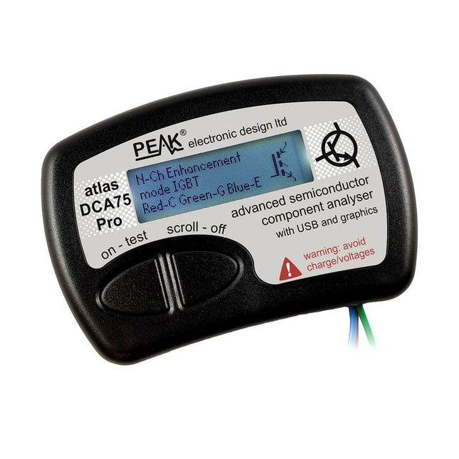
The DCA75 Pro is a great instrument that combines ease-of-use with amazing features. It can automatically identify a huge range of semiconductors, automatically identify pinouts and measure detailed parameters.
Features
Built-in graphics display (now backlit) to show detailed schematic of the component you're testing as well as pinout and measurement data
USB connectivity to allow curve tracing, data storage/retrieval and device matching on your Windows PC (Windows 7 and higher)
Single internal AAA alkaline cell for standalone operation
Component Support
Bipolar transistors (NPN/PNP inc Silicon/Germanium)
Darlington transistors (NPN/PNP)
Enhancement mode MOSFETs (N-Ch and P-Ch)
Depletion mode MOSFETs (N-Ch and P-Ch)
Junction FETs (N-Ch and P-Ch). Both symmetrical and asymmetrical types
Enhancement IGBTs (N-Ch and P-Ch)
Diodes and diode networks (2 and 3 lead types)
Zener diodes (up to about 9 V)
Voltage regulators (up to about 8 V)
LEDs and bi-colour LEDs (2 lead and 3 lead types)
Low power sensitive Triacs and Thyristors (<10 mA trigger and hold)
Measurements
BJT current gain (hFE)
BJT base emitter voltage (Vbe)
BJT collector leakage current
MOSFET on and off gate threshold voltages
MOSFET transconductance
JFET pinch-off voltage
JFET transconductance
JFET IDSS (drain current for Vgs=0)
IGBT on and off gate threshold voltages
IGBT transconductance
Voltage regulator output voltage
Voltage regulator quiescent current consumption
Voltage regulator drop-out voltage
Zener voltage
Diode forward voltage drop
Specifications
Analyzer type
Semiconductor components
Component detection
Automatic
Pinout detection
Automatic, connect any way round
Display type
Graphic LCD (now backlit)
Interface type
USB for optional PC connection
PC functions
Curve tracing (Windows 7 and higher)
Software
Included on USB drive for Windows 7 and higher
Battery
Single AAA cell (supplied)
Included
Peak Atlas DCA75 Pro
PC software on a USB Flash Drive for Windows 11, 10, 8, 7, XP
Micro USB cable
Fitted universal premium hook probes
AAA Alkaline battery
Downloads
Datasheet (EN)
User Guide (EN)
User Guide (IT)
Software Installation Guide (EN)
Software and Firmware Package
With the JOY-iT PS1440-C-Pro, you get a programmable laboratory power supply that delivers DC voltages ranging from 0.01 to 60 V and DC currents from 0.01 to 24 A at the voltage output.
The intuitive control panel allows you to program, store, and recall up to 9 different DC voltage settings. You can also configure individual protection and limiting functions—such as overvoltage protection. All settings are easily adjusted via the keypad and/or rotary control and are clearly shown on the high-resolution 2.4" color display.
For enhanced connectivity, the PS1440-C-Pro includes an RS485 interface for robust, long-distance communication. This makes it ideal for complex setups where signal stability, noise immunity, and reliable data transfer are critical. The included connector ensures a secure connection, improving the overall reliability and performance of your laboratory equipment setup.
Features
Complete device ready for immediate use
RS485 interface
Battery charging function
Values can be entered conveniently via keypad
Over current & over voltage protection adjustable
Integrated RTC, NTC temperature sensor
Included detailed documentation in English, German & French
Specifications
Input voltage
230 V
Output voltage
060 V
Output current
0-24 A
Output power
0-1440 W
Input voltage accuracy
±1% +5 digits
Output voltage accuracy
±0.3% +3 digits
Output current accuracy
±0.5% +5 digits
Battery voltage
±0.5% +3 digits
Input voltage measurement resolution
0.01 V
Output voltage measurement resolution
0.01 V
Current measurement resolution
0.01 V
Battery voltage measurement resolution
0.01 V
Response time in constant voltage mode
2 ms @ 0.1-5 A
Load regulation in constant voltage mode
±0.1% +2 digits
Load regulation in constant current mode
±0.1% +3 digits
Measuring range electric charge
0-9999.99 Ah
Measuring range energy
0-9999.99 Wh
Statistical errors in electric charge & energy
±2%
Output ripple
100 mV VPP @ 12 V150 mV VPP @ 24 V
Sensor temperature detection range
−10~100°C (0-200°F)
Sensor temperature detection accuracy
±3°C (±6°F)
Working mode
Step-down operation
Screen brightness setting
Level 0-5, 6 levels in total
Permissible working temperature
−10~40°C (0-104°F)
Dimensions
170 x 93 x 340 mm
Included
JOY-iT PS1440-C Power Supply
2-pin connector for RS485 interface
Power cord
Manual
Downloads
Datasheet
MODBUS Protocol
PC Software
Driver for Windows
Elektor GREEN and GOLD members can download their digital edition here.
Not a member yet? Click here.
PIO Programming on the Raspberry Pi PicoNine Instructions, Many Possibilities
Breaking AI Out of the BrowserUsing AI CLIs to Code, Compile, and Validate Embedded Projects
The Scrutiny DebuggerDebug, Visualize, and Test Embedded C/C++ Code
Sigfox Breakout Board (1)A Self-Built Radio BoB
Low-Noise Power Supply (2)Construction, Assembly, and Practical Implementation
Simple Signal Generator Using the RP2040Analog and Digital Signals for Around €10
Navigating the Future of Smart Homes with Matter and Edge AIAre Matter’s Latest Updates and the Rise of Edge AI Finally Giving Engineers the Tools to Build the Intelligent, Seamless Smart Homes Users Have Been Promised?
Differential Pressure SensorsPredictive Maintenance in HVAC-Systems
Security by DesignEngineering Fundamentals Limit Failure
Embedded Security Is No Longer Optional
CRA and PQC Are Rewriting Embedded Security PrioritiesWhy Even Small IoT and Industrial Firms Need an Upgrade Plan
embedded world 2026An Interview With Benedikt Weyerer, Executive Director of embedded world
Hands on with I3CUsing Hardware from ST and Microchip
The BLEnky ProjectRapid Prototyping of Bluetooth Low Energy Applications
Pulse Width ModulationFrom a Simple On/Off Thermostat to a Smoothed DC Analog Signal
AudiotronicsEar-Pleasing Electronics for DIY Construction
From Life’s ExperienceRead The F...ing Manual!
ESP32 Audio Transceiver Board (Part 4)Tuning the Clocks - And a Wired Option
2026: An AI OdysseyThe 2025 Vibe-Coding Hangover
Symmetrical DC LoadDC Load, Static or Dynamic, and Symmetrical
Counting Faces with MaixCAMAn Easy Way to Capture Audience Sizes
Elektor GREEN en GOLD leden kunnen deze uitgave hier downloaden.
Nog geen lid? Klik hier om een lidmaatschap af te sluiten.
Kleine warmtebeeldcameraeen op Arduino UNO gebaseerde DHZ-oplossing
Project-update #3: ESP32-gebaseerde energiemeterintegratie en test met Home Assistant
2024: een AI-odysseeobjectdetectie verbeteren met verfijnde technieken
De Raspberry Pi gaat AInieuwe kit bevat M.2 HAT+ met AI-versneller
Sensoren voor weerstationswat is de beste keuze?
Lees uw analoge watermeter uit met AI (1)koppel uw oude watermeter met het IoT!
GSM-alarmdraadloze garagebeveiliging
Low-power Thread-devices geoptimaliseerd en onder de loep genomenweinig vermogen... weinig inspanning?
Uit het leven gegrepende genderkloof
Zelfbouw-nevelkamermaak onzichtbare straling zichtbaar
SparkFun Thing Plus Mattereen veelzijdig Matter-gebaseerd IoT development board
IoT-retrofittenRS232-apparaten klaarstomen voor Industry 4.0
Stimuleer het IoT met 8-bit MCU’s
Technologie stimuleert duurzaamheidvooruitgang leidt in veel toepassingen tot efficiënter energiegebruik
AWS voor Arduino en co. (1)AWS IoT ExpressLink in de praktijk
Luchtstroomdetector met alleen een Arduinozonder externe sensoren!
Lekdetectorverbonden met de Arduino-cloud
Kristallenvreemde onderdelen
Universele logger voor de tuinAI-tuinieren komt een stapje dichterbij
Analoge 1kHz-generatorsinussen met geringe vervorming
Miletus: webapps offline gebruikeninclusief toegang tot het systeem en het apparaat!
Van 4G naar 5Gis het echt zo eenvoudig?
Alle begin......gaat symmetrisch
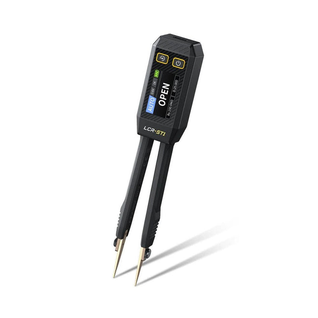
The FNIRSI LCR-ST1 is a compact, multifunctional, and smart LCR tester that supports automatic measurements of resistance, capacitance, inductance, diode testing, and continuity.
Its 1.14-inch color display combined with a convenient magnetic adsorption function enhances ease of use, while the built-in 250 mAh lithium battery ensures long-lasting performance. The device supports three frequency ranges (100 Hz, 1 kHz and 10 kHz) and offers 0.3 V and 0.6 V RMS test levels for versatile testing applications.
The unique tweezer-shaped design of the LCR-ST1 is ideal for delicate tasks in confined spaces and enables fast and accurate testing of electronic components. Its light weight and portable design make it an invaluable tool for both field and laboratory use.
Whether you are an experienced engineer or just starting out in electronics, the LCR-ST1 delivers reliable and accurate measurement results, allowing you to complete your tasks with greater efficiency and precision.
Features
Offers 3 test frequencies (100 Hz, 1 kHz, 10 kHz) and 2 test voltage levels.
Features automatic component identification for faster and more reliable measurements.
High-resolution 1.14-inch color display for clear readouts.
Supports automatic data recording and storage.
The tweezer tips are made from gold-plated brass for enhanced durability and conductivity.
Specifications
Resistance Range
10 mΩ – 10 MΩ
Capacitance Range
1 pF – 22 mF
Inductance Range
1 μh – 10 H
Diode
On voltage 0.7 V
Frequency Test
100 Hz, 1k Hz, 10 KHz
Level Test
0.3 V, 0.6 V RMS
Parameter Display
ESR, D value, Q value, Z value, X value
Display
1.14" HD color screen
Charging Interface
USB-C, 5 V/1 A
Power Supply
Built-in 250 mAh lithium battery
Auto Recognition Measurement
Yes
Replaceable Tweezer Head
Yes
Auto Shutdown
Yes
Data Hold
Yes
History Record
Connect to PC to view and export
Dimensions
28 x 19 x 150 mm
Weight
41 g
Included
1x LCR-ST1 SMD Tweezers
2x Hook Tips
1x Magnetic Patch
1x USB cable
1x Tool bag
1x Manual
Downloads
Manual
Firmware V1.6
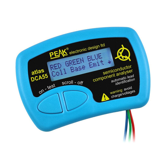
The Peak Atlas DCA55 is great for automatically identifying the type of semiconductor on the test leads as well as the pinout and many other parameters.
Supports transistors MOSFETs, JFETs (gate pin only can be identified), diodes, LEDs and lots more. Automatically identifies type of component, pinout and other important parameters. Now features transistor leakage measurement and Germanium/Silicon identification.
Component Support
Bipolar transistors (NPN/PNP inc Silicon/Germanium)
Darlington transistors (NPN/PNP)
Enhancement mode MOSFETs (N-Ch and P-Ch)
Depletion mode MOSFETs (N-Ch and P-Ch)
Junction FETs (N-Ch and P-Ch). Only gate lead identified
Diodes and diode networks (2 and 3 lead types)
LEDs and bi-colour LEDs (2 lead and 3 lead types)
Low power sensitive Triacs and Thyristors (<5 mA trigger and hold)
Measurements
Part type identification
Pinout identification
BJT current gain (hFE)
BJT base emitter voltage (Vbe)
BJT collector leakage current
MOSFET gate threshold voltage
Diode forward voltage drop (Vf)
Specifications
Analyzer type
Transistors, Diodes, LEDs, MOSFETs, JFETs
Pinout detection
Full pinout (only Gate on JFETs)
Pinout configuration
Connect any way round
Transistor measurements
Vbe, hFE, Iceo
MOSFET measurements
Vgs(on)
Diode measurements
Vf
Probe type
Universal grabber type
Battery
Single AAA cell (supplied). Life typically 1300 ops
Test conditions
Typically 5 mA, 5 V peak
Display type
Alphanumeric LCD (with backlight)
Included
Peak Atlas DCA55 Semiconductor Analyzer
Comprehensive illustrated user guide
Fitted universal hook probes
AAA Alkaline battery
Downloads
Datasheet (EN)
User Guide (EN)
User Guide (IT)
50+ Android Apps with Raspberry Pi, ESP32 and Arduino
This book is about developing apps for Android compatible mobile devices using the MIT App Inventor online development environment. MIT App Inventor projects can be in either standalone mode or use an external processor. In standalone mode, the developed application runs only on the mobile device (e.g. Android). In external processor-based applications, the mobile device communicates with an external microcontroller-based processor, such as Raspberry Pi, Arduino, ESP8266, ESP32, etc.
In this book, many tested and fully working projects are given both in standalone mode and using an external processor. Full design steps, block programs, circuit diagrams, QR codes and full program listings are given for all projects.
The projects developed in this book include:
Using the text-to-speech component
Intonating a received SMS message
Sending SMS messages
Making telephone calls using a contacts list
Using the GPS and Pin-pointing our location on a map
Speech recognition and speech translation to another language
Controlling multiple relays by speech commands
Projects for the Raspberry Pi, ESP32 and Arduino using Bluetooth and Wi-Fi
MIT APP Inventor and Node-RED projects for the Raspberry Pi
The book is unique in that it is currently the only book that teaches how to develop projects using Wi-Fi and Node-RED with MIT App Inventor. The book is aimed at students, hobbyists, and anyone interested in developing apps for mobile devices.
All projects presented in this book have been developed using the MIT App Inventor visual programming language. There is no need to write any text-based programs. All projects are compatible with Android-based mobile devices. Full program listings for all projects as well as detailed program descriptions are given in the book. Users should be able to use the projects as they are presented, modifying them to suit their own needs.
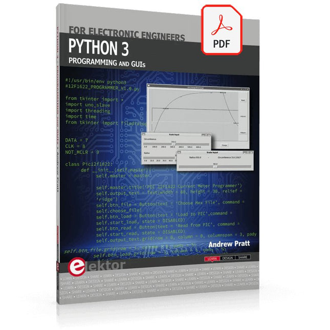
This is the second edition of a book aimed at engineers, scientists, and hobbyists who want to interface PCs with hardware projects using graphical user interfaces. Desktop and web-based applications are covered.
The programming language used is Python 3, which is one of the most popular languages around: speed of programming being a key feature. The book has been revised and updated with an emphasis on getting the user to produce practical designs with ease – a text editor is all that is required to produce Python programs.
Hardware interfacing is achieved using an Arduino Uno as a remote slave. A full description and source code of the communication interface is given in the book. The slave provides digital and analog input and outputs. Multiple Unos can be included in one project with all control code written in Python and running on a PC One project involves a PIC microcontroller with the code provided that can be loaded into the PIC using the Uno.
The web applications and server are all implemented in Python, allowing you to access your electronic hardware over the Internet. The Raspberry Pi computer can be used as your web server. An introductory chapter is provided to get you started with using Linux.
The book is written for use with Debian or variations including Mint or Ubuntu. All of the programs in the book are freely available, ready to use and experiment with by way of a download from Elektor.
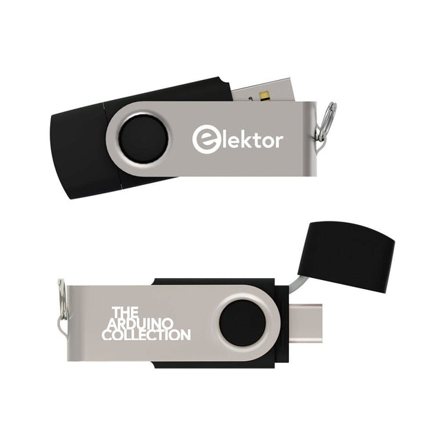
This USB Stick contains more than 300 Arduino-related articles published in Elektor Magazine. The content includes both background articles and projects on the following topics:
Software & hardware development: Tutorials on Arduino software development using Arduino IDE, Atmel Studio, Shields, and essential programming concepts.
Learning: The Microcontroller Bootcamp offers a structured approach to programming embedded systems.
Data acquisition & measurement: Projects such as a 16-bit data logger, lathe tachometer, and an AC grid analyzer for capturing and analyzing real-time signals.
Wireless communication: Learn how to implement wireless networks, create an Android interface, and communicate effectively with microcontrollers.
Robotics and automation: This covers the Arduino Nano Robot Controller, supporting boards for automation, and explores various Arduino shields to enhance functionality.
Self-build projects: Unique projects such as laser projection, Numitron clock and thermometer, ELF receiver, Theremino, and touch LED interfaces highlight creative applications.
Whether you're a beginner or an experienced maker, this collection is a valuable resource for learning, experimenting, and pushing the boundaries of Arduino technology.
Pfiffige Lösungen mit Arduino Pro Mini und ATmega328-Boards
Mit einem einfachen Arduino Pro Mini Board und ein paar weiteren Bauteilen lassen sich heute für wenig Geld Projekte realisieren, die vor 20 oder 30 Jahren noch undenkbar waren oder ein kleines Vermögen gekostet hätten. Von einfachen LED-Effekten bis zur Ladestation – die den Akku auf Herz und Nieren prüft – ist in diesem Buch vieles dabei.
Als Mikrocontroller dient bei allen beschriebenen Projekten der ATmega328, der mit seinen 20 Ein- und Ausgangsleitungen unzählige Möglichkeiten zum Messen, Schalten und Steuern bietet. Mit einem 7-Segment-Display und ein paar Widerständen lässt sich daraus z. B. ein Voltmeter bauen oder mittels NTC ein Thermometer. Die Arduino-Plattform bietet dabei die perfekte Entwicklungsumgebung zum Programmieren der Boards.
Neben den ganz konkreten Projekten soll das Buch aber auch das nötige Wissen vermitteln, um eigene Ideen zu realisieren. Wie misst man was? Welches ist der geeignete Transistor, um verschiedene Verbraucher zu schalten? Wann ist man mit einem IC besser bedient, oder wie schaltet man Netzspannung? Auch batteriebetriebene Projekte mit LilyPad sind ausführlich thematisiert. Ebenso vielerlei Motoren, vom einfachen Gleichstrommotor bis zum Schrittmotor.
Sensoren sind ein weiteres spannendes Thema. Nur zwei Beispiele: Mit einem winzigen Bauteil lässt sich tatsächlich messen, dass der Luftdruck am Fußboden höher ist als auf Tischhöhe. Mit einem simplen Infrarot-Empfänger kann man ausgedienten Fernbedienungen ein zweites Leben schenken und die Wohnung damit steuern.
The OWON SDS1102 is an affordable benchtop digital oscilloscope that combines solid performance with essential measurement features. This 2-channel oscilloscope offers a 100 MHz bandwidth, a 1 GS/s sampling rate, a 7-inch LCD display, and a 10 kpts memory depth, making it a practical choice for everyday electronics testing, troubleshooting, and education.
The SDS1102 features a simplified trigger system with level and edge triggering, making it easy to capture and analyze common signals. It is designed for applications that do not require deep memory or advanced trigger functions, offering a straightforward and cost-effective solution for basic signal analysis.
Features
Bandwidth: 100 MHz
2 channels
Sample rate: 1 GS/s
Ultra-thin body
7-inch high-res LCD
SCPI and LabVIEW supported
Specifications
Bandwidth
100 MHz
Horizontal Scale (s/div)
5 ns/div – 1000 s/div
Channel
2
Vertical Sensitivity
5 mV/div – 5 V/div (at input)
DC Gain Accuracy
3%
Vertical Resolution (A/D)
8 bits (2 channels simultaneously)
Input
Input Impedance
1 MΩ, 10 pF
Input Coupling
AC, DC, GND
Max Input Voltage
±400 V, CATI, CATII
Passive probes
х1; х10
Probe Attenuation Factor
х1; х10; х100; х1000
Trigger System
Trigger Mode
Auto, Normal, Single
Trigger Type
Edge, Video
Edge Trigger Source
CH1, CH2
Video Trigger
Sampling Type
Real-time
Sample Rate
1 GS/s
Equivalent Sample Rate
No
Wavelength
10K pts
Interpolation
sin(x)/x
Measurement and Mathematical Treatment System
Automatic Measurement
Vpp, Vavg, RMS, Frequency, Period, Vmax, Vmin, Vtop, Vbase, Width, Overshoot, Pre-shootRise time, Fall time, +Width, -Width, +Duty, -Duty, Delay A→B, Delay A→B, area, cycle area
Math Functions
Addition, Subtraction, Multiplication, Division, FFT
General Characteristics
Display type
7" color LCD
Display Resolution
800 x 480
Power
100-240 V, 45-440 Hz, <15 W
Dimensions
301 x 70 x 152 mm
Weight
1.1 kg
Included
1x OWON SDS1102 Oscilloscope
2x Oscilloscope probes
1x Probe adjust
1x Mains power cord
1x USB cable
1x CD-Rom
1x Quick guide
Downloads
Quick Guide
Manual
PC Software
SCPI Commands