Learning circuit design the fun way
Welcome to the world of electronics!
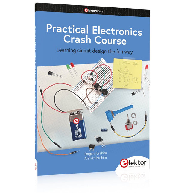
Getting started in electronics is not as difficult as you may think. Using this book, you will explore and learn the most important electrical and electronics engineering concepts in a fun way by doing various experiments and by simulating circuits. It will teach you electronics practically without getting into complex technical jargon and long calculations. As a result, you will be creating your own projects soon.
No prior knowledge of electronics is required, only some basic algebra is used in a few simple calculations. Many tested and working projects and simulations are presented to familiarise yourself with the construction of electronic circuits. Circuit simulation is introduced at an early stage to enable you to experiment with circuits easily without breaking anything.
You will learn:
The concepts of voltage, current, and power
AC and DC
Basic lamp circuits with switches
Passive components: resistors, capacitors & inductors
RC & RCL circuits
Electromagnetism
Loudspeakers, relays, buzzers, and transformers
Active components: diodes & LEDs, bipolar transistors & MOSFETs
Transistor-based switching circuits
Optocoupler circuits
Astable & monostable multivibrators
Using the 555 timer IC
The operational amplifier
Digital logic
Advanced examples: amplifiers, oscillators, filters, and sensors
Test and measurement tools
Microcontrollers: Arduino UNO, ESP32, Raspberry Pi Pico, and Raspberry Pi
Reading datasheets and best practices for selecting components
EMC & EMI and norms & regulations
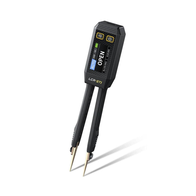
The FNIRSI LCR-ST1 is a compact, multifunctional, and smart LCR tester that supports automatic measurements of resistance, capacitance, inductance, diode testing, and continuity.
Its 1.14-inch color display combined with a convenient magnetic adsorption function enhances ease of use, while the built-in 250 mAh lithium battery ensures long-lasting performance. The device supports three frequency ranges (100 Hz, 1 kHz and 10 kHz) and offers 0.3 V and 0.6 V RMS test levels for versatile testing applications.
The unique tweezer-shaped design of the LCR-ST1 is ideal for delicate tasks in confined spaces and enables fast and accurate testing of electronic components. Its light weight and portable design make it an invaluable tool for both field and laboratory use.
Whether you are an experienced engineer or just starting out in electronics, the LCR-ST1 delivers reliable and accurate measurement results, allowing you to complete your tasks with greater efficiency and precision.
Features
Offers 3 test frequencies (100 Hz, 1 kHz, 10 kHz) and 2 test voltage levels.
Features automatic component identification for faster and more reliable measurements.
High-resolution 1.14-inch color display for clear readouts.
Supports automatic data recording and storage.
The tweezer tips are made from gold-plated brass for enhanced durability and conductivity.
Specifications
Resistance Range
10 mΩ – 10 MΩ
Capacitance Range
1 pF – 22 mF
Inductance Range
1 μh – 10 H
Diode
On voltage 0.7 V
Frequency Test
100 Hz, 1k Hz, 10 KHz
Level Test
0.3 V, 0.6 V RMS
Parameter Display
ESR, D value, Q value, Z value, X value
Display
1.14" HD color screen
Charging Interface
USB-C, 5 V/1 A
Power Supply
Built-in 250 mAh lithium battery
Auto Recognition Measurement
Yes
Replaceable Tweezer Head
Yes
Auto Shutdown
Yes
Data Hold
Yes
History Record
Connect to PC to view and export
Dimensions
28 x 19 x 150 mm
Weight
41 g
Included
1x LCR-ST1 SMD Tweezers
2x Hook Tips
1x Magnetic Patch
1x USB cable
1x Tool bag
1x Manual
Downloads
Manual
Firmware V1.6
Im vorliegenden Buch wird das weltweit verbreitete 0G-Netzwerk Sigfox zunächst detailliert vorgestellt. Danach wird auf der Basis eines leistungsfähigen Arduino-Sigfox-Boards eine universelle Sigfox-Test-, Mess- und Simulations-Plattform hardwaremäßig entwickelt und softwaremäßig betrieben. Diese Sigfox-Feldstation stellt dem Anwender eine Vielzahl von Möglichkeiten zur Verfügung: Sensoren, Aktoren und Displays inkl. GPS-Modul und Solargenerator.
Alle Schaltungsteile (inkl. den 3D-Plott-Vorlagen für ein passendes Stationsgehäuse) und sämtlichen Softwaremodule werden offen gelegt, so dass der Leser damit weitere Sigfox-Feldstationen nach seinen eigenen Vorstellungen und Bedürfnissen entwickeln und problemlos einsetzen kann.
Die Visualisierung, Auswertung und Speicherung der erfassten Felddaten wird anhand eines Freeware Dashboard Programms, mit Schnittstelle zu Google Maps, ausführlich beschrieben.
Themenauswahl:
Industrie 4.0, Internet of Things, 0G-Netzwerke
Das Sigfox-Netzwerk: Übertragungstechnik, Uplink/Downlink, das Monarch-Konzept, Geolokalisierung, Sigfox-Atlas-Konzept
Das Sigfox-Backend, die Callbacks und die REST-API
Aufbau der universellen Sigfox-Test-, Mess- und Simulations-Plattform auf der Basis des Arduino-Sigfox-Moduls MKR FOX1200
Die grundlegende Betriebssoftware für alle Komponenten
Die Arduino-Sigfox-Bibliothek und der Sigfox-Betrieb – Anmeldung bei der Sigfox-Cloud, Aussendung von Mess- und Zustandswerten
Die Sigfox-Callbacks – Der Datentransfer von der Sigfox-Cloud zum Anwender: E-Mails, Mess- und Zustandswerte, GeoLoc-Daten
Die individuelle Gestaltung von Anwender-Dashboards
Hardwareerweiterungen: HMI-Display, Thermoelementverstärker, Multichannel-Gassensor, Feinstaubsensor, GPS-Modul und vieles mehr
Kommerzielle Sigfox-Stationen
The OWON SDS1102 is an affordable benchtop digital oscilloscope that combines solid performance with essential measurement features. This 2-channel oscilloscope offers a 100 MHz bandwidth, a 1 GS/s sampling rate, a 7-inch LCD display, and a 10 kpts memory depth, making it a practical choice for everyday electronics testing, troubleshooting, and education.
The SDS1102 features a simplified trigger system with level and edge triggering, making it easy to capture and analyze common signals. It is designed for applications that do not require deep memory or advanced trigger functions, offering a straightforward and cost-effective solution for basic signal analysis.
Features
Bandwidth: 100 MHz
2 channels
Sample rate: 1 GS/s
Ultra-thin body
7-inch high-res LCD
SCPI and LabVIEW supported
Specifications
Bandwidth
100 MHz
Horizontal Scale (s/div)
5 ns/div – 1000 s/div
Channel
2
Vertical Sensitivity
5 mV/div – 5 V/div (at input)
DC Gain Accuracy
3%
Vertical Resolution (A/D)
8 bits (2 channels simultaneously)
Input
Input Impedance
1 MΩ, 10 pF
Input Coupling
AC, DC, GND
Max Input Voltage
±400 V, CATI, CATII
Passive probes
х1; х10
Probe Attenuation Factor
х1; х10; х100; х1000
Trigger System
Trigger Mode
Auto, Normal, Single
Trigger Type
Edge, Video
Edge Trigger Source
CH1, CH2
Video Trigger
Sampling Type
Real-time
Sample Rate
1 GS/s
Equivalent Sample Rate
No
Wavelength
10K pts
Interpolation
sin(x)/x
Measurement and Mathematical Treatment System
Automatic Measurement
Vpp, Vavg, RMS, Frequency, Period, Vmax, Vmin, Vtop, Vbase, Width, Overshoot, Pre-shootRise time, Fall time, +Width, -Width, +Duty, -Duty, Delay A→B, Delay A→B, area, cycle area
Math Functions
Addition, Subtraction, Multiplication, Division, FFT
General Characteristics
Display type
7" color LCD
Display Resolution
800 x 480
Power
100-240 V, 45-440 Hz, <15 W
Dimensions
301 x 70 x 152 mm
Weight
1.1 kg
Included
1x OWON SDS1102 Oscilloscope
2x Oscilloscope probes
1x Probe adjust
1x Mains power cord
1x USB cable
1x CD-Rom
1x Quick guide
Downloads
Quick Guide
Manual
PC Software
SCPI Commands
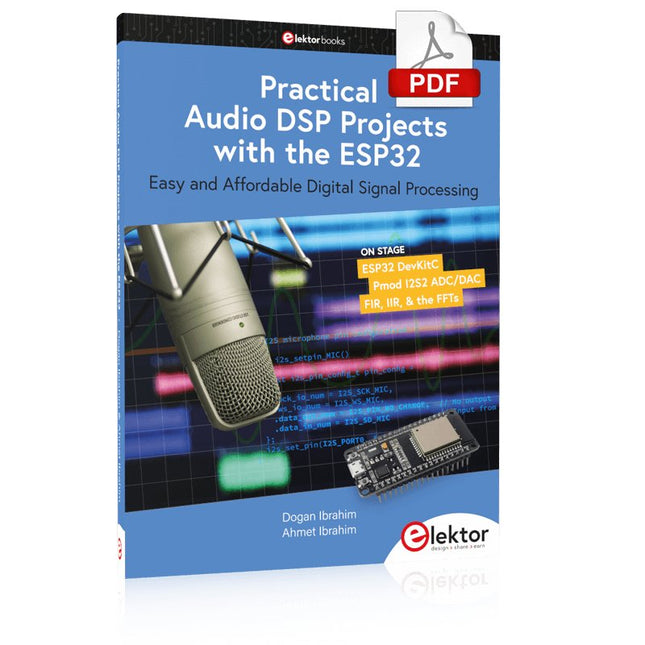
Easy and Affordable Digital Signal ProcessingThe aim of this book is to teach the basic principles of Digital Signal Processing (DSP) and to introduce it from a practical point of view using the bare minimum of mathematics. Only the basic level of discrete-time systems theory is given, sufficient to implement DSP applications in real time. The practical implementations are described in real time using the highly popular ESP32 DevKitC microcontroller development board. With the low cost and extremely popular ESP32 microcontroller, you should be able to design elementary DSP projects with sampling frequencies within the audio range. All programming is done using the popular Arduino IDE in conjunction with the C language compiler.After laying a solid foundation of DSP theory and pertinent discussions on the main DSP software tools on the market, the book presents the following audio-based sound and DSP projects:
Using an I²S-based digital microphone to capture audio sound
Using an I²S-based class-D audio amplifier and speaker
Playing MP3 music stored on an SD card through an I²S-based amplifier and speaker
Playing MP3 music files stored in ESP32 flash memory through an I²S-based amplifier and speaker
Mono and stereo Internet radio with I²S-based amplifiers and speakers
Text-to-speech output with an I²S-based amplifier and speaker
Using the volume control in I²S-based amplifier and speaker systems
A speaking event counter with an I²S-based amplifier and speaker
An adjustable sinewave generator with I²S-based amplifier and speaker
Using the Pmod I²S2 24-bit fast ADC/DAC module
Digital low-pass and band-pass real-time FIR filter design with external and internal A/D and D/A conversion
Digital low-pass and band-pass real-time IIR filter design with external and internal A/D and D/A conversion
Fast Fourier Transforms (FFT)
USB-Logikanalysatoren am PC mit Arduino, Raspberry Pi und Co
Schritt-für-Schritt-Anleitungen führen Sie in die Analyse moderner Protokolle von I²C, SPI, UART, RS-232, NeoPixel, WS28xx, HD44780 und 1-Wire ein. Anhand von zahlreichen Experimentierschaltungen mit dem Raspberry Pi Pico, Arduino Uno und dem Bus Pirate üben Sie die praxisnahe Anwendung gängiger USB-Logikanalysatoren ein.
Alle in diesem Buch vorgestellten Experimentierschaltungen wurden vollständig getestet und sind funktionsfähig. Die notwendigen Programmlistings sind enthalten, es sind keine besonderen Programmier- oder Elektronikkenntnisse für diese Schaltungen notwendig. Es werden die Programmiersprachen MicroPython und C mit den Entwicklungsumgebungen Thonny und Arduino IDE eingesetzt.
Dieses Buch verwendet mehrere Modelle flexibler und weit verbreiteter USB-Logikanalysatoren und zeigt die Stärken und Schwächen jeder Preisklasse. Sie werden kennenlernen, welche Kriterien für Ihre Arbeit wichtig sind und in der Lage sein, das für Sie passende Gerät zu finden.
Egal ob Arduino, Raspberry Pi oder Raspberry Pi Pico: Die abgebildeten Beispielschaltungen ermöglichen einen schnellen Start in die Protokollanalyse und können auch als Grundlage für eigene weitere Experimente dienen.
Sie werden alle wichtigen Begriffe und Zusammenhänge kennenlernen, eigene Experimente durchführen, selbstständig Protokolle analysieren und nach der Lektüre dieses Buches – im Bereich der digitalen Signale und Protokolle – ein umfassendes Wissen aufgebaut haben.
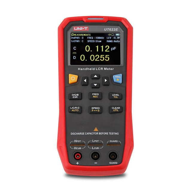
The UT622E handheld LCR meter features powerful functions, high accuracy, fast speed, and long standby time. With a clear and intuitive 2.8-inch TFT LCD display, large-capacity rechargeable battery, and 100 kHz test frequency, the meter can be used for longstanding accurate and convenient measurement in any occasion.
It is suitable for the measurement and screening of inductance, capacitance, and resistance in laboratories, production lines, maintenance points, etc.
Features
Max. test frequency: 100 kHz
Accuracy: 0.1%
Display count: 99999
Max. test rate: 20 times/s
DCR: Yes
Connectivity: Mini-USB
Display: 2.8" TFT LCD
Specifications
Testfrequency
100 Hz, 120 Hz, 1 kHz, 10 kHz, 100 kHz
Test level
0.1 Vmrs, 0.3 Vrms, 1 Vrms
Output impedance
100 Ω
Measurement parameters
Primary: L/C/R/Z/DCRSecondary: D/Q/Θ/ESR
DSR speed test
Fast (20 times/s), medium (5 times/s), or slow (2 times/s)
Range
Auto/Hold
Tolerance range
1%~20%
Equivalent mode
Series/Parallel
Clearing connection
Open/Short circuit
Fuse of test ports
0.1 A/250 V
Communication interface
Mini-USB
MAX reading of primary parameters
99999
MIN resolution
0.0001
Maximum accuracy
0.10%
L
0.00 µH~99.999 H
C
0.00 pF~99.999 mF
Z/R
0.0000 Ω~9.9999 MΩ
ESR
0.0000 Ω~999.99 Ω
D
0.0000~9.9999
Q
0.0000~99999
Θ
-179.9°~179.9°
DCR
0.01 mΩ~20.000 MΩ
Power supply
3.7 V/1800 mAh lithium polymer battery
Display
2.8" TFT LCD (320x240)
Dimensions
93 x 192 x 44 mm
Weight
420 g
Included
UT622E LCR meter
Short circuit board
Four-terminal kelvin test leads
USB cable
Manual
Downloads
Datasheet
Manual
Software
Elektor GREEN en GOLD leden kunnen deze uitgave hier downloaden.Nog geen lid? Klik hier om een lidmaatschap af te sluiten.
Kiesschijftelefoon als afstandsbedieningvoor licht kies 1; voor koffie kies 2
GPS-gebaseerde snelheidsmeternooit meer bekeuringen
RGB-stroboscoop met Arduinokleurige toepassing van een nuttig instrument
Draadloze nooddrukknopmeer veiligheid met LoRa
Alle begin......volgt de emitter
Vrij te kiezen onafhankelijke hystereseniveaus voor comparatorenmet simulaties, spreadsheets en algebra
Impedantie-analyzer op basis van een ESP32simpel, weinig onderdelen en goedkoop!
Oost West Lab Bestzelfbouw moet gestimuleerd!
Het MCCAB Arduino Nano Training Boardalle hardware voor de “Microcontrollers Hands-On Course”
Uit het leven gegrepenmodern luddisme
Sensor-ABC: de DS18B20 temperatuursensoraansluiting op de 1-Wire bus
Gaan Matter en Thread het Smart Home redden?nieuwe standaarden om het slimme huis te vereenvoudigen
Een kwestie van samenwerkingontwikkelen met het Thing Plus Matter Board en Simplicity Studio
Elektor IIIIinfographicIoT en sensoren
Matter, ExpressLink, Rainmaker – waar hebben we het over?vraaggesprek met Amey Inamdar van Espressif
De juiste keuze van microcontroller-ontwikkelkitsvoor IoT- en IIoT-toepassingen
Condensatoren gedragen zich niet altijd capacitief!
Een NTP-klok met CircuitPythonwaarom zou je deze programmeertaal gebruiken?
Bouw een cool IoT-display'met de Phambili Newt
De doppler-bewegingssensor HB100theorie en praktijk
Een gids voor puristisch programmeren (deel 1)voor STM32 en andere controllers
Siglent SDM3045X-multimeter
Microprocessoren voor embedded systemenvreemde onderdelen
Microcontroller-documentatie verklaarddeel 3: blokschema’s en meer
Low-power LoRa-weerstationbouw zelf een weerstation met een groot bereik
Transverter voor de 70cm-band
Klimaat aan ingenieurssnelheid is geboden!
Hexadoku
AVR Architecture and Programming An in-depth look at the 8-bit AVR architecture found in ATtiny and ATmega microcontrollers, mainly from a software and programming point of view. Explore the AVR architecture using C and assembly language in Microchip Studio (formerly Atmel Studio) with ATtiny microcontrollers. Learn the details of how AVR microcontrollers work internally, including the internal registers and memory map of ATtiny devices. Program ATtiny microcontrollers using an Atmel-ICE programmer/debugger, or use a cheap hobby programmer, or even an Arduino Uno as a programmer. Most code examples can be run using the Microchip Studio AVR simulator. Learn to write programs for ATtiny microcontrollers in assembly language. See how assembly language is converted to machine code instructions by the assembler program. Find out how programs written in the C programming language end up as assembly language and finally as machine code instructions. Use the Microchip Studio debugger in combination with a hardware USB programmer/debugger to test assembly and C language programs, or use the Microchip Studio AVR simulator. DIP packaged ATtiny microcontrollers are used in this volume for easy use on electronic breadboards, targeting mainly the ATtiny13(A) and ATtiny25/45/85. Learn about instruction timing and clocks in AVR microcontrollers using ATtiny devices. Be on your way to becoming an AVR expert with advanced debugging and programming skills.
Cette compilation comprend des articles intégrés de l'actuel Elektor entre juillet 2012 et novembre 2014.
Les documents suivants sont inclus dans le numéro de document (PDF) avec la fonction de navigation disponible et les articles sont intéressants.
Diese Ausgabe steht allen GOLD- und GREEN-Mitgliedern auf der ElektorMagazine-Website zum Download bereit!
Sie sind noch kein Mitglied? Hier klicken!
Audio-DSP-FX-Prozessor-BoardTeil 1: Eigenschaften und Design
50 Jahre Elektor in englischer Sprache
KiCad 8Neue und aktualisierte Funktionen
MultiCalculator-KitEin Elektronikrechner-Bausatz von Elektor mit Arduino
Preiswerte GNSS-RTK-SystemeFür zentimetergenaue Positionsbestimmung
Platinenlayout und SicherheitTipps für sichere und langlebige Leiterplatten
Opamp-TesterFür Audio- und andere Anwendungen
Projekt-Update #4 : Energiemessgerät mit ESP32Energieüberwachung mit MQTT
Echtzeit-Spektrumanalyzer mit Waveguide-Technologie und Multi-Schnittstellen-PCsAaronia etabliert neues Produktsegment und präsentiert erste Prototypen auf der electronica in München
electronica 2024Highspeed und robuste Board-to Board Steckverbinder
InduktivitätenSpulen und Ferrite anwendungsorientiert selektieren
EMI-Abschirmung zur Einhaltung der elektromagnetischen Konformität
Das ultimative Werkzeug für jeden Elektronik-EnthusiastenUnendliche Möglichkeiten mit Red Pitaya und 1.000+ Click Boards™
Die 100 % durchgängige Flussmittelseele
Siglent stellt seine neue Vektornetzwerkanalysator-Plattform SNA6000A vor
HDI der MittelklasseEin neuer ökonomischer PCB Pooling Service für hochpolige BGAs
Ferngesteuerte IoT-EntwicklungDie einzige Lösung für Fernunterricht und Entwicklung in der Embedded-Industrie
Herausforderungen der DFM-Analyse für Flex- und Rigid-Flex-Design
Aus dem Leben gegriffenMikrotechnophobie
Feliz Natal: 3D-WeihnachtsbaumEine 3D-Platine mit preiswertem 32-Bit-Mikrocontroller
Aller Anfang......muss nicht schwer sein: Weiter geht es mit den Opamps!
Ein autonomer SensorknotenProjekt-Update #1: Reduzierung der Leerlauf-Stromaufnahme mit externer RTC mit Leistungsschalter
2024: Eine Odyssee in die KIEin Blick zurück in die Zukunft
LED-Displays mit dem MAX7219Ein praktischer Ansatz für einen großartigen Chip
Projekt 2.0Korrekturen, Updates und Leserbriefe
VibroTactile-HandschuheEin Durchbruch für Parkinson-Patienten?