Von den Machern von MagPi, dem offiziellen Raspberry Pi Magazin
Starten Sie jetzt mit dem Raspberry Pi 5, dem neuesten und besten Minicomputer von Raspberry Pi – und lernen Sie, mit diesem unglaublichen Computer zu programmieren und Projekte zu erstellen.
In diesem Buch finden Sie außerdem jede Menge kreative Ideen und Tipps, die Sie mit dem Raspberry Pi 4, dem Raspberry Pi Zero 2 W und dem Raspberry Pi Pico W umsetzen können.
Mit den neuesten Reviews, Tutorials, Projekten, Anleitungen und mehr ist dies Ihre ultimative Ressource für den Raspberry Pi!
228 Seiten über Raspberry Pi
Alles, was Sie über den Raspberry Pi 5 wissen müssen
Erste Schritte für jeden Raspberry Pi
Viel Spaß mit Elektronik und dem Pico W
Inspirierende Projekte für Ihre nächste Bauidee
Lernen Sie MicroPython, indem Sie ein Handheld bauen
Erste Schritte mit dem Raspberry Pi Camera Modul
Künstliche Intelligenz: Bauen Sie Ihren eigenen GPT Chatbot
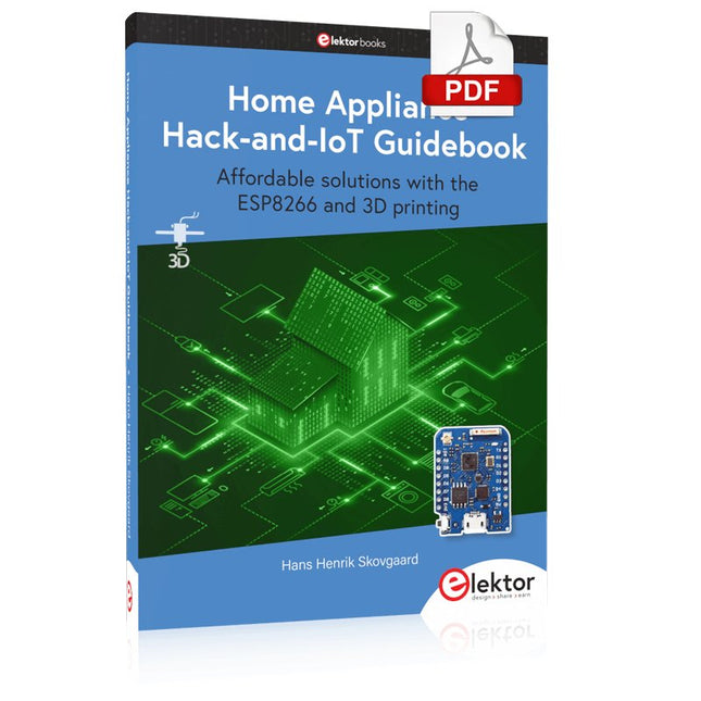
Affordable solutions with the ESP8266 and 3D printing
If you are looking for a small yet powerful IoT device, you are likely to come across the ESP8266 and compatible products on the market today. One of these, the Wemos/Lolin D1 Mini Pro board strikes a remarkable balance between cost and performance. A small and very affordable prototype board, the D1 Mini Pro stands out with its WiFi functionality and a 16-Mbytes flash memory for easy creation of a flash file system. In addition, there are sufficient input and output pins (only one analog input though) to support PWM, I²C, and One-Wire systems to mention but a few. The book describes the operation, modding, construction, and programming of home appliances including a colorful smart home accessory, a refrigerator/greenhouse controller, an AC powerline monitor, a door lock monitor, and an IKEA Trådfri controller.
As a benefit, all firmware developed for these DIY, "IoT-ized" devices can be updated over-the-air (OTA).
For most of the designs in the book, a small printed circuit board (PCB) and an enclosure are presented so readers can have a finished and attractive-looking product. Readers having – or with access to! – a 3D printer can "print" the suggested enclosures at home or in a shop.
Some of the constructions benefit from a Raspberry Pi configured as a gateway or cms server. This is also described in detail with all the necessary configuring.
You don’t need to be an expert but the prerequisites to successful replication of the projects include basic skills with PC software including the ability to surf the Internet. In terms of hardware, you should be comfortable with soldering and generally assembling the PCBs presented in the book.
All custom software written for the IoT devices, the PCB layouts, and 3D print files described in the book are available for free downloading.
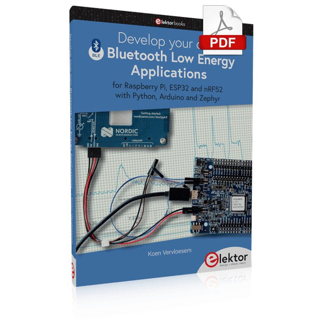
For Raspberry Pi, ESP32 and nRF52 with Python, Arduino and Zephyr
Bluetooth Low Energy (BLE) radio chips are ubiquitous from Raspberry Pi to light bulbs. BLE is an elaborate technology with a comprehensive specification, but the basics are quite accessible.
A progressive and systematic approach will lead you far in mastering this wireless communication technique, which is essential for working in low power scenarios.
In this book, you’ll learn how to:
Discover BLE devices in the neighborhood by listening to their advertisements.
Create your own BLE devices advertising data.
Connect to BLE devices such as heart rate monitors and proximity reporters.
Create secure connections to BLE devices with encryption and authentication.
Understand BLE service and profile specifications and implement them.
Reverse engineer a BLE device with a proprietary implementation and control it with your own software.
Make your BLE devices use as little power as possible.
This book shows you the ropes of BLE programming with Python and the Bleak library on a Raspberry Pi or PC, with C++ and NimBLE-Arduino on Espressif’s ESP32 development boards, and with C on one of the development boards supported by the Zephyr real-time operating system, such as Nordic Semiconductor's nRF52 boards.
Starting with a very little amount of theory, you’ll develop code right from the beginning. After you’ve completed this book, you’ll know enough to create your own BLE applications.
Réalisés par les créateurs du MagPi, le magazine officiel de Raspberry Pi
Démarrez avec le Raspberry Pi 5, le dernier-né et le plus performant de la famille des nano-ordinateurs Raspberry Pi. Apprenez à coder et à réaliser des projets avec cet ordinateur étonnant.
Dans ce manuel dédié au Raspberry Pi 5, nous vous proposons aussi de nombreuses idées de projets également réalisables avec le Raspberry Pi 4, le Raspberry Pi Zero 2 W et le Raspberry Pi Pico W.
Avec des tutoriels, des projets pratiques, des essais techniques, des guides et bien plus encore, il s’agit de la ressource ultime pour le Raspberry Pi !
228 pages sur le Raspberry Pi
Tout ce que vous devez savoir sur le Raspberry Pi 5
Prise en main de tous les Raspberry Pi
Amusez-vous et apprenez l’électronique avec le Pico W
Des projets inspirants pour vous donner des idées de réalisations
Apprenez μPython en construisant une mini-console
Démarrez avec le module caméra Raspberry Pi
Intelligence artificielle, codage de son propre agent ChatGP
Raspberry Pi 5 provides two four-lane MIPI connectors, each of which can support either a camera or a display. These connectors use the same 22-way, 0.5 mm-pitch “mini” FPC format as the Compute Module Development Kit, and require adapter cables to connect to the 15-way, 1 mm-pitch “standard” format connectors on current Raspbery Pi camera and display products.These mini-to-standard adapter cables for cameras and displays (note that a camera cable should not be used with a display, and vice versa) are available in 200 mm, 300 mm and 500 mm lengths.
Met de Raspberry Pi heeft u voor slechts een paar tientjes een complete computer in handen, waar op eenvoudige wijze allerlei elektronica aangesloten kan worden. In deze 2e herziene en uitgebreide versie gaan we in op een van de sterke kanten van de Raspberry Pi: de combinatie van programmeren en elektronica.
Na een korte introductie van de Raspberry Pi wordt de benodigde software geïnstalleerd. Op de SD-kaart die u bij dit boek kunt aanschaffen, is die allemaal al aanwezig voor de Raspberry Pi. Aan de (optionele) Windows PC kant gebeurt dit met gratis software die u kunt downloaden.
Daarna volgt een beknopte inleiding in het besturingssysteem Linux en gaan we programmeren in Bash, Python en JavaScript. De nadruk ligt hierbij op Python, maar in alle gevallen houden we het kort. We bespreken net voldoende zodat u de projecten kunt begrijpen en aan uw wensen aanpassen, en gaan dan aan de slag met leuke projecten.
Maar liefst 45 spannende en interessante projecten worden in detail besproken en uitgelegd. Van wisselknipperlicht, aansluiten van een elektromotor, het verwerken en maken van analoge signalen tot lichtmeter en temperatuurregeling. Maar ook gecompliceerdere projecten zoals een motorsnelheidsregeling, webserver met CGI, client-server applicaties en Xwindows programma‘s. U kunt dit boek gebruiken als projecten boek en de projecten nabouwen en in de praktijk inzetten. Door de duidelijke uitleg, schema‘s en foto‘s van de opstellingen op een steekbord wordt het nabouwen een erg leuke bezigheid.
RPi
Alle software voor de RPi is voorgeïnstalleerd op een SD-kaart die u bij dit boek kunt aanschaffen. Dat wil zeggen dat alle software en drivers voor SSH, SPI, I²C, GPIO, PWM, muziek, Python Ontwikkelversie, wxPython, IdleX en de seriële verbinding gegarandeerd werken. Tevens staan alle broncodes van de projecten uitdit boek op deze kaart.
Windows-PC
In het gratis download-pakket dat bij dit boek hoort, vindt u de software die in dit boek gebruikt wordt op de Windows-PC handig bij elkaar in een enkel ZIP-bestand. Alle software is gratis. Tevens bevat het pakket een filmpje van de Nutteloze Doos (Useless Machine) van project 13.4.
Software download-pakket
WinOscillo
Putty
Xming
WinSCP
DiskImager
Notepad2
IdleX
Useless Box film
Diese Ausgabe steht allen GOLD- und GREEN-Mitgliedern auf der ElektorMagazine-Website zum Download bereit!
Sie sind noch kein Mitglied? Hier klicken!
DIY-SolarakkusÜber den Selbstbau von Energiespeichern für Solaranlagen
Solarmodul-SimulatorFür Test und Optimierung von MPP-Trackern und Invertern
Der STM32-Edge-KI-WettbewerbEntdecken Sie den neuen STM32N6 und nehmen Sie am Wettbewerb um 5.000 € teil!
Erweiterung der BandlückeWarum gibt es so viel Interesse an SiC und GaN?
Power-Bank für NotebooksVerlängern Sie das Leben Ihres alten Laptops!
Medizinische RoboterÜberwindung technischer und regulatorischer Hürden
Frostwächter für ObstpflanzenMit Temperatur-Datenlogger
Das analoge DingDer Arduino des Analog-Computings?
Sparsames NetzrelaisMit über 90% Leistungsreduzierung
Verbesserung der DC-Last ET5410A+Keep cool and be quiet!
electronica 2024 im Rückblick
Elektromagnetische VerträglichkeitEMV kurz und bündig!
Aller Anfang......muss nicht schwer sein: Aktive Filter
Verlustleistung reduzieren mit AbleitkondensatorenEin cleverer Einsatz von kapazitiver Reaktanz
Preiswerter 12-Bit-Digital-Analog-Wandler MCP4725Mit EEPROM-Feature für sicheres Einschaltverhalten
Fnirsi LCR-ST1, die intelligente LCR-SMD-Pinzette
Test- und Messlabor mit Raspberry PiDas Wichtigste zuerst: Der ADC
Elektronischer LastwiderstandEin Projekt aus der Kiste
2025: Eine Odyssee in die KIEinige Projekte für das neue Jahr
Projekt-Update: Modulares DC-Leistungsmessgerät AmpVolt v2.0100 Ampere und mehr!
Projekt 2.0
Ethische Transparenz sichtbar gemachtErgebnisse der Umfrage 2024 von Ethics in Electronics
Elektor Audio-DSP FX-Prozessor-BoardTeil 2: Anwendungen erstellen
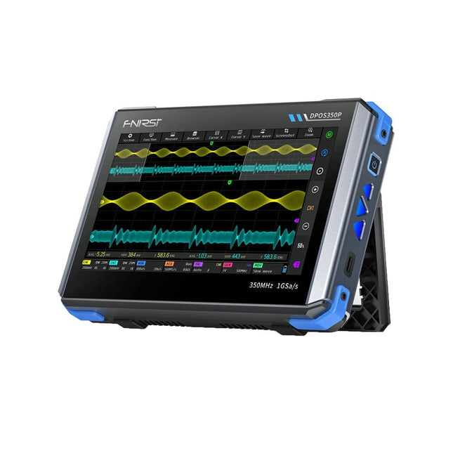
2 Channels • 350 MHz • 1 GSa/s • 50,000 wfm/s • 7 inch Touchscreen
The FNIRSI DPOS350P is a sleek 4-in-1 powerhouse in tablet form! This compact and portable device packs serious functionality: it combines a 2-channel oscilloscope (350 MHz), a signal generator (50 MHz), a frequency response analyzer (50 MHz), and a spectrum analyzer (200 kHz–350 MHz) – all in one unit.
Whether you're in R&D, troubleshooting, or field testing, the DPOS350P delivers the tools you need to measure, generate, analyze, and visualize electronic signals with precision and clarity. Its responsive high-resolution touchscreen and intuitive controls make signal analysis fast, flexible and efficient.
Features
Powerful Multi-Function Integration
350 MHz 2-channel oscilloscope with 1 GSa/s real-time sampling
50 MHz signal generator with 14 standard + custom waveforms
Spectrum analyzer (200 kHz–350 MHz): Perfect for EMI, RF & HF testing
Frequency response analyzer (FRA) up to 50 MHz
High-Performance Waveform Capture
50,000 wfm/s refresh rate for real-time signal clarity
350 MHz bandwidth (single-channel mode)
Detects rare and low-probability anomalies
Crisp Display & Smooth Operation
7" IPS touchscreen (1024 x 600 resolution)
Switch between grayscale and color temperature display
Easy to operate in various test environments
Reliable, Protected & Fast-Charging
High-voltage protection up to 400 V
Fast charging with QC 18 W (full charge in 2 hours)
Built for stable long-term operation
Data Storage & Export
Save up to 500 waveform records + 90 screenshots
USB export for easy reporting and offline analysis
Specifications
General
Display
7 inch (IPS full viewing angle)
Resolution
1024 x 600 pixels
Interaction mode
Capacitive touch screen
Total power consumption
10 W
Power-on configuration
5 presets
Charging
QC 18 W, 12 V/1.5 A (USB-C)
Battery
3.7 V, 8000 mAh lithium battery
Battery life
approx. 3 hours in operation, 5 hours standby
Heat dissipation
Air cooling
Expansion interface
USB data port
Automatic shutdown
15~60 minutes / off
Firmware upgrade
Support .iso image upgrade
Languages
English / Portuguese / Russian / Chinese
Dimensions
190 x 128 x 37 mm
Oscilloscope
Analog channels
2
Analog bandwidth
350 MHz
Rise time
1ns
Real-time sampling rate
1 GSa/s
Memory depth
60 Kpts
Input impedance
1 MΩ / 14PF
Time base range
5ns ~ 50s
Roll time base
50ms ~ 50s
Vertical sensitivity
2 mV ~ 20 V (1X)
Vertical range
16 mV ~ 160 V (1X)
DC accuracy
±2%
Time accuracy
±0.01%
Input coupling
DC / AC
Probe attenuation
1X / 10X / 100X
Hardware bandwidth limit
150M / 20M
High resolution mode
8bit ~ 16bit
Parameter measurements
12 types
Cursor measurement
Time, period, frequency, level, voltage
Trigger detection
Digital trigger
Trigger channel
CH1 / CH2
Trigger mode
Auto / Single / Normal
Trigger edge
Rising edge / Falling edge
Trigger suppression
L1 ~ L3
Trigger level
Manual / automatic 10% ~ 90%
Screenshot storage
90 pictures
Waveform storage
500 groups
Background grid
Display / hide
Waveform movement
Coarse adjustment / fine adjustment
Overvoltage protection
Withstand voltage 400 V
Waveform brightness
Adjustable
Simple FFT display
Yes
Digital fluorescence
Yes
Color temperature display
Yes
X-Y mode
Yes
ZOOM time base
Yes
One-key automatic adjustment
Yes
One-key return to zero
Yes
Data browser
Yes
Signal Generator
Waveform types
14 standard functions + captured waveform
Frequency
0~50 MHz (sine wave only, other waveforms up to 10M/5M/3M)
Amplitude
0~5 VPP
Offset
-2.5 V ~ +2.5V
Duty cycle
0.1~99.9%
Frequency resolution
1 Hz
Amplitude resolution
1 mV
Offset resolution
1 mV
Duty cycle resolution
0.1%
Customizable captured waveform
500 groups
Frequency Response Analyzer (FRA)
Excitation signal frequency
100 Hz ~ 50 MHz
Excitation signal amplitude
0~5 VPP
Excitation signal offset
-2.5V ~ +2.5V
Excitation frequency count
20~500
Cursor measurement
Frequency / gain / phase
Operating mode
Single / cyclic
System calibration
Yes
Spectrum Analyzer
Conversion method
FFT
FFT length
4K ~ 32K
Frequency range
200 KHz ~ 350 MHz
Level range
-60 dBmV ~ +260 dBmV
Cursor measurement
Frequency / amplitude
Marking parameter
Maximum energy harmonic
Waterfall chart
Yes
3D waterfall chart
Yes
Automatic adjustment
Yes
System calibration
Yes
Included
1x FNIRSI DPOS350P Oscilloscope (4-in-1)
2x 350 MHz Probes
1x QC 18 W Fast Charger (EU)
1x USB-C Cable
1x Alligator Clip
1x Storage Bag
1x Manual
Downloads
Manual
Firmware
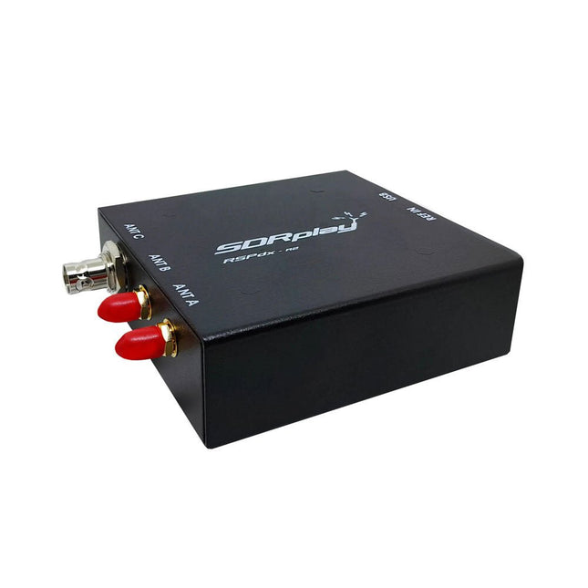
The SDRplay RSPdx-R2 is a wideband full featured single-tuner 14-bit SDR receiver which covers the entire RF spectrum from 1 kHz to 2 GHz giving up to 10 MHz of spectrum visibility. It contains three antenna ports, two of which use SMA connectors and operate across the full 1 kHz to 2 GHz range and the third uses a BNC connector which operates up to 200 MHz.
The RSPdx-R2 is an enhanced version of the RSPdx with further design improvements for use at frequencies below 2 MHz. Housed in a strong steel case, in addition to the functionality of the RSP1B, the RSPdx-R2 provides three software selectable antenna inputs and an external clock input. It offers excellent performance through HF and VHF frequencies all the way up to 2 GHz. The RSPdx-R2 also supports an "HDR mode" optimised for the demanding radio reception conditions below 2 MHz.
The RSPdx-R2, when used in conjunction with SDRplay’s own software, introduces a special HDR (High Dynamic Range) mode for reception within selected bands below 2 MHz. HDR mode delivers improved intermodulation performance and fewer spurious responses for those challenging bands.
Features
Covers all frequencies from 1 kHz through VLF, LF, MW, HF, VHF, UHF and L-band to 2 GHz, with no gaps
Receive, monitor and record up to 10 MHz of spectrum at a time
Significantly improved noise performance below 1 MHz (i.e. for some MF, LF and below)
Improved dynamic range below 2 MHz both in tuner mode and HDR mode
HDR mode below 2 MHz giving overall dynamic range and selectivity advantages
Software selectable choice of 3 antenna ports
External clock input for synchronisation purposes, or connection to GPS reference clock for extra frequency accuracy
Excellent dynamic range for challenging reception conditions
Free use of Windows-based SDRuno software (check website for versions supported)
Free use of SDRconnect SDR and server software for Windows, MacOS and Linux (Check website for versions supported)
Multiplatform driver and API support including Windows, Linux, Mac and Raspberry Pi 4/5
Strong and growing software support network
Calibrated S meter/RF power and SNR measurement with SDRuno (including datalogging to .CSV file capability)
Documented API provided to allow demodulator or application development on multiple platforms
Applications (Amateur)
Shortwave radio listening
Broadcast DXing (AM/FM/TV)
Panadaptor
Aircraft (ADS-B and ATC)
Slow Scan TV
Multi-amateur band monitoring
WSPR & digital modes
Weather fax (HF and satellite)
Satellite monitoring
Geostationary environmental satellites
Trunked radio
Utility and emergency service monitoring
Fast and effective antenna comparison
Applications (Industrial)
Spectrum Analyser
Surveillance
Wireless microphone monitoring
RF surveying
IoT receiver chain
Signal logging
RFI/EMC detection
Broadcast integrity monitoring
Spectrum monitoring
Power measurement
Applications (Educational/Scientific)
Teaching
Receiver design
Radio astronomy
Passive radar
Ionosonde
Spectrum analyser
Receiver for IoT sensor projects
Antenna research
Specifications
Frequency Range
1 kHz – 2 GHz
Antenna Connector
SMA
Antenna Impedance
50 Ohms
Current Consumption (Typical)
190 mA @ >60 MHz (excl. Bias-T)120 mA @ <60 MHz (excl. Bias-T)
USB Connector
USB-B
Maximum Input Power
+0 dBm Continuous+10 dBm Short Duration
ADC Sample Rates
2-10.66 MSPS
ADC Number of Bits
14 bit 2-6.048 MSPS12 bit 6.048-8.064 MSPS10 bit 8.064-9.216 MSPS8 bit >9.216 MSPS
Bias-T
4.7 V100 mA guaranteed
Reference
0.5ppm 24 MHz TCXOFrequency error trimmable to 0.01ppm in field
Operating Temperature
−10˚C to +60˚C
Dimensions
113 x 94 x 35 mm
Weight
315 g
Downloads
Datasheet
Software
RSPdx-R2 vs RSPduo
RSPdx-R2
RSPduo
Continuous coverage from 1 kHz to 2 GHz
✓
✓
Up to 10 MHz visible bandwidth
✓
✓
14-bit ADC silicon technology plus multiple high-performance input filters
✓
✓
Software selectable AM/FM & DAB broadcast band notch filters
✓
✓
4.7 V Bias-T for powering external remote antenna amplifier
✓
✓
Powers over the USB cable with a simple type B socket
✓
✓
50Ω SMA antenna input(s) for 1 kHz to 2 GHz operation (software selectable)
2
2
Additional software selectable Hi-Z input for up to 30 Mhz operation
✓
Additional software selectable 50Ω BNC input for up to 200 MHz operation
✓
Additional LF/VLF filter for below 500 kHz
✓
24 MHz reference clock input (+ output on RSPduo)
✓
✓
Dual tuners enabling reception on 2 totally independent 2 MHz ranges
✓
Dual tuners enabling diversity reception using SDRuno
✓
Rugged black painted steel case
✓
✓
Overall performance below 2 MHz for MW and LF
++
+
Multiple simultaneous applications
+
++
Performance in challenging fading conditions (*using diversity tuning)
+
*++
Diese Ausgabe steht allen GOLD- und GREEN-Mitgliedern auf der ElektorMagazine-Website zum Download bereit!
Sie sind noch kein Mitglied? Hier klicken!
Ein autonomer SensorknotenLoRa-Datenübertragung und Solar-Stromversorgung
Elektor eXpansion Board v1.0Für ESP32-S3 und andere XIAO-Controller-Boards
Modelleisenbahn mit KameraEinbau eines ESP32-CAM-Moduls
Breitband-Magnetantenne für LangwelleMehrere Sender ohne Abstimmung
TensorFlow Lite auf kleinen MikrocontrollernEin (sehr) einsteigerfreundlicher Blickwinkel
Ein Hub für RS-422 und RS-485Verdrahten Sie Ihre Geräte wie einen Stern
HF-SondeMit LED-Balkenanzeige
Aller Anfang...muss nicht schwer sein: mehr Verstärkerschaltungen
MultiLayer-SegmentierungEin neuer Ansatz für adressierbare LED-Streifen
Open VarioOpen-Source Multifunktions-Variometer für Gleitschirmflieger
Aus dem Leben gegriffenÜber die Selbstverständlichkeit der Dinge
KI-gestützter WasserzählerTeil 2: Firmware-Installation, Anwendung und Montage
Intelligente LandwirtschaftML-basierte Schädlingserkennung mit IoT-Vernetzung
Warum Anybus CompactCom die ideale Wahl für die industrielle Embedded-Kommunikation ist
Kommunikationsstandard IQRFZuverlässigkeit für verlustbehaftete drahtlose Mesh-Netzwerke mit niedriger Rate
Bau eines intelligenten AgrarrobotersWelche wesentlichen technischen Überlegungen und Herausforderungen müssen Entwickler von Agrarrobotern berücksichtigen?
Audio-Notchfilter mit einstellbarer FrequenzUniverselle Lösung zur Unterdrückung von Frequenzen im Audiobereich
Das System LeoINAGPSNützliche Einblicke in Ihr Elektrofahrzeug
Solarbetriebener LoRa-KnotenEine modulare, kompakte und vielseitige IoT-Lösung
AWS für Arduino und Co.Teil 2: Daten senden mit AWS-IoT-ExpressLink
Projekt 2.0Korrekturen, Updates und Leserbriefe
2024: Eine Odyssee in die KIBeschleuniger: Desktop vs. Embedded, ein Blick auf einige Optionen
ESP32-ReichweitenverlängererEine einfache Antennenmodifikation
Mit dem Elektor Arduino Nano Trainingsboard (MCCAB) eigene Projekte realisieren
Der Mikrocontroller ist das wohl faszinierendste Teilgebiet der Elektronik, denn aufgrund der Vielzahl von Funktionen, die er auf seinem Chip vereinigt, ist er für den Entwickler ein universelles Multi-Tool zur Realisierung seiner Projekte. Praktisch jedes Gerät des täglichen Gebrauchs wird heute von einem Mikrocontroller gesteuert. Für einen elektronischen Laien blieb es aufgrund der Komplexität bisher allerdings ein Wunschtraum, eigene Ideen mit einem Mikrocontroller zu realisieren. Das Arduino-Konzept hat den Einsatz von Mikrocontrollern weitgehend vereinfacht, sodass jetzt auch Laien eigene Elektronik-Ideen mit einem Mikrocontroller verwirklichen können.
Buch & Hardware im Bundle: 'Learning by Doing'
Dieses im Bundle mitgelieferte Buch (im großen A4-Format) zeigt, wie man auch ohne große Erfahrung in Elektronik und Programmiersprachen eigene Projekte mit einem Mikrocontroller realisieren kann. Es ist ein Mikrocontroller-Praxiskurs für Einsteiger, denn nach einem Überblick über die Interna des Mikrocontrollers und einer Einführung in die Programmiersprache C liegt der Schwerpunkt des Kurses auf den praktischen Übungen. Der Leser eignet sich die erforderlichen Kenntnisse durch 'Learning by Doing' an: in dem umfangreichen Praxisteil mit 12 Projekten und 46 Übungen wird das im vorderen Teil des Buches Gelernte mit vielen Beispielen unterlegt. Die Übungen sind dabei so aufgebaut, dass der Bearbeiter eine Aufgabenstellung erhält, die er mit seinem im Theorieteil des Buches aufgebauten Wissen löst. Für jede Übung gibt es anschließend eine ausführlich erklärte und kommentierte Musterlösung, die dem Bearbeiter bei Problemen weiterhilft und die er mit seiner eigenen Lösung vergleichen kann.
Arduino IDE
In der Arduino IDE, einer Software-Entwicklungsumgebung, die kostenlos auf den eigenen PC heruntergeladen werden kann und die das gesamte Softwarepaket enthält, das für ein eigenes Mikrocontroller-Projekt benötigt wird, schreibt der Bearbeiter mit dem Editor der IDE seine Programme („Apps“) in der Programmiersprache C. Der in die Arduino IDE integrierte Compiler übersetzt sie in die Bits und Bytes, die der Mikrocontroller versteht und die dann über ein USB-Kabel in den Speicher des Mikrocontrollers auf dem Elektor Arduino Nano Trainingsboard (MCCAB) geladen werden.
Externe Sensoren, Motoren oder Baugruppen abfragen oder steuern
Das Elektor Arduino Nano Trainingsboard (MCCAB) enthält neben einem Mikrocontrollermodul Arduino Nano alle für die Übungen benötigten Bauteile wie Leuchtdioden, Schalter, Taster, akustische Signalgeber usw. Auch externe Sensoren, Motoren oder Baugruppen können mit diesem Mikrocontroller-Übungssystem abgefragt oder gesteuert werden.
Technische Daten (Arduino Nano Trainingsboard MCCAB)
Stromversorgung
Über die USB-Verbindung des zur Erstellung der Programme sowieso angeschlossenen PCs oder ein externes Netzteil (nicht im Lieferumfang enthalten)
Betriebsspannung
+5 Vcc
Eingangsspannung
Alle Eingänge
0 V bis +5 V
VX1 und VX2
+8 V bis +12 V (nur bei Verwendung eines externen Netzteils)
Mikrocontrollermodul
Arduino Nano
Hardwareperipherie
LCD
2x16 Zeichen
Potenziometer P1 & P2
JP3: Auswahl der Betriebsspannung von P1 & P2
Verteiler
SV4: Verteiler für die BetriebsspannungenSV5, SV6: Verteiler für die Ein-/Ausgänge des Mikrocontrollers
Schalter und Taster
RESET-Taster auf dem Arduino Nano-Modul6x Tastschalter K1 … K66x Schiebeschalter S1 … S6JP2: Verbindung der Schalter mit den Eingängen des Mikrocontrollers
Summer
Piezo-Summer Buzzer1 mit Steckbrücke auf JP6
Leuchtanzeigen
LED L auf dem Arduino Nano-Modul, verbunden mit GPIO D1311x LED: Zustandsanzeige für die Ein-/AusgängeJP6: Verbindung der LEDs LD10 … LD20 mit den GPIOs D2 … D12
Serielle SchnittstellenSPI & I²C
JP4: Auswahl des Signals an Pin X der SPI-Steckerleiste SV12SV9 bis SV12: SPI-Interface (3,3 V/5 V) bzw. I²C-Interface
Schaltausgang für externe Geräte
SV1, SV7: Schaltausgang (maximal +24 V/160 mA, extern zugeführt)SV2: 2x13 Pins zum Anschluss externer Module
3x3 LED-Matrix (9 rote LEDs)
SV3: Spalten der 3x3 LED-Matrix (Ausgänge D6 … D8)JP1: Verbindung der Reihen mit den GPIOs D3 … D5
Software
Library MCCABLib
Steuerung der Hardware-Komponenten (Schalter, Taster, Leuchtdioden, 3x3 LED-Matrix, Summer) auf dem MCCAB Trainingsboard
Betriebstemperatur
bis +40 °C
Abmessungen
100 x 100 x 20 mm
Technische Daten (Arduino Nano)
Mikrocontroller
ATmega328P
Architektur
AVR
Betriebsspannung
5 V
Flashspeicher
32 KB, davon 2 KB vom Bootloader belegt
SRAM
2 KB
Taktfrequenz
16 MHz
Analoge IN-Pins
8
EEPROM
1 KB
DC-Strom pro I/O-Pin
40 mA an einem I/O-Pin, insgesamt maximal 200 mA an allen Pins gemeinsam
Eingangsspannung
7-12 V
Digitale I/O-Pins
22 (6 davon sind PWM-fähig)
PWM-Ausgänge
6
Stromverbrauch
19 mA
Abmessungen
18 x 45 mm
Gewicht
7 g
Lieferumfang
Elektor Arduino Nano MCCAB Trainingsboard
Arduino Nano
Buch: Mikrocontroller-Praxiskurs für Arduino-Einsteiger