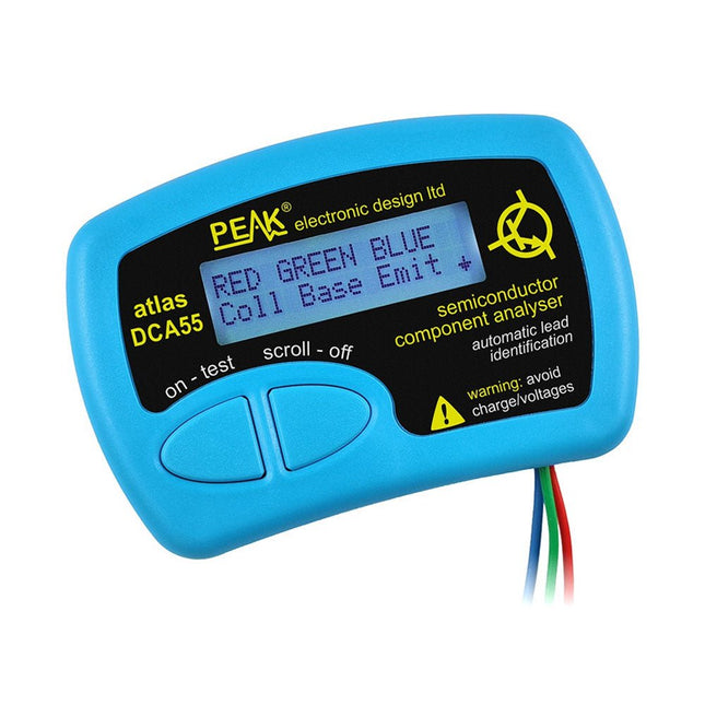
The Peak Atlas DCA55 is great for automatically identifying the type of semiconductor on the test leads as well as the pinout and many other parameters.
Supports transistors MOSFETs, JFETs (gate pin only can be identified), diodes, LEDs and lots more. Automatically identifies type of component, pinout and other important parameters. Now features transistor leakage measurement and Germanium/Silicon identification.
Component Support
Bipolar transistors (NPN/PNP inc Silicon/Germanium)
Darlington transistors (NPN/PNP)
Enhancement mode MOSFETs (N-Ch and P-Ch)
Depletion mode MOSFETs (N-Ch and P-Ch)
Junction FETs (N-Ch and P-Ch). Only gate lead identified
Diodes and diode networks (2 and 3 lead types)
LEDs and bi-colour LEDs (2 lead and 3 lead types)
Low power sensitive Triacs and Thyristors (<5 mA trigger and hold)
Measurements
Part type identification
Pinout identification
BJT current gain (hFE)
BJT base emitter voltage (Vbe)
BJT collector leakage current
MOSFET gate threshold voltage
Diode forward voltage drop (Vf)
Specifications
Analyzer type
Transistors, Diodes, LEDs, MOSFETs, JFETs
Pinout detection
Full pinout (only Gate on JFETs)
Pinout configuration
Connect any way round
Transistor measurements
Vbe, hFE, Iceo
MOSFET measurements
Vgs(on)
Diode measurements
Vf
Probe type
Universal grabber type
Battery
Single AAA cell (supplied). Life typically 1300 ops
Test conditions
Typically 5 mA, 5 V peak
Display type
Alphanumeric LCD (with backlight)
Included
Peak Atlas DCA55 Semiconductor Analyzer
Comprehensive illustrated user guide
Fitted universal hook probes
AAA Alkaline battery
Downloads
Datasheet (EN)
User Guide (EN)
User Guide (IT)
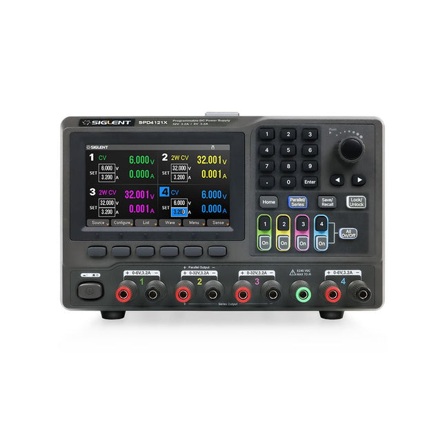
The Siglent SPD4121X is a 4-channel DC Linear Programmable Power Supply equipped with a 4.3-inch TFT-LCD display, friendly human-machine interface, and excellent performance indicators. Real-time waveform display provides engineers with an informative user interface.
SPD4121X offers a total output power of 285 W with a resolution of 1 mV/1 mA. The maximum voltage and current for each channel are as follows:
CH1: 15 V/1.5 A
CH2: 12 V/10 A
CH3: 12 V/10 A
CH4: 15 V/1.5 A
Features
Rated output power: 285 W
Rated voltage: 32 V, 12 V, 30 V
Up to four high-precision power supplies with independent controllable outputs, supporting CH2 and CH3 series and parallel connections
Clear graphical interface with waveform and timer display modes
5-digit voltage and current display with minimum resolution of 1 mV, 1 mA
Fast output response time: <50us
The high current channel support remote voltage compensation sense function. The maximum compensation voltage is 0.6 V
Overvoltage protection and overcurrent protection or safe and accurate operation
Equipped with a 4.3-inch TFT-LCD display (480 x 272 resolution)
USB and LAN standard communication
USB-GPIB module is optional
Excellent channel density with up to 4 channels in a 3U half rack package
Internal data storage for setups and parameters
Embedded Web Server with instrument communication that doesn’t require software installation
Fully SCPI programming command set support as well as a LabView driver for remote control and system automation
Specifications
SPD4323X
SPD4121X
SPD4306X
Channel Output
CH1: Voltage 0 to 6 V Current 0 to 3.2 ACH2: Voltage 0 to 32 V Current 0 to 3.2 ACH3: Voltage 0 to 32 V Current 0 to 3.2 ACH4: Voltage 0 to 6 V Current 0 to 3.2 A
CH1: Voltage 0 to 15 V Current 0 to 1.5 ACH2: Voltage 0 to 12 V Current 0 to 10 ACH3: Voltage 0 to 12 V Current 0 to 10 ACH4: Voltage 0 to 15 V Current 0 to 1.5 A
CH1: Voltage 0 to 15 V Current 0 to 1.5 ACH2: Voltage 0 to 30 V Current 0 to 6 ACH3: Voltage 0 to 30 V Current 0 to 6 ACH4: Voltage 0 to 15 V Current 0 to 1 A
Resolution
1 mV, 1 mA
1 mV, 1 mA
1 mV, 1 mA
Setting Accuracy
Voltage: ±(0.03% of reading+10) mV, Current: ±(0.3% of reading+10) mA
Voltage: ±(0.03% of reading+10) mV, Current: ±(0.3% of reading+10) mA
Voltage: ±(0.03% of reading+10) mV, Current: ±(0.3% of reading+10) mA
Readback Accuracy
Voltage: ±(0.03% of reading+10) mV, Current: ±(0.3% of reading+10) mA
Voltage: ±(0.03% of reading+10) mV, Current: ±(0.3% of reading+10) mA
Voltage: ±(0.03% of reading+10) mV, Current: ±(0.3% of reading+10) mA
Display
4.3" TFT-LCD 5-digit voltage and current display
4.3" TFT-LCD 5-digit voltage and current display
4.3" TFT-LCD 5-digit voltage and current display
Output power
240 W
285 W
400 W
Included
1x Siglent SPD4121X Power Supply
1x Power cord (EU)
1x Output test cord (3 A)
1x USB cable
1x Quick start guide
Downloads
Datasheet
Manual
Quick start
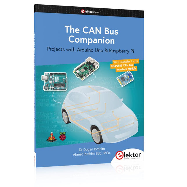
This book details the use of the Arduino Uno and the Raspberry Pi 4 in practical CAN bus based projects. Using either the Arduino Uno or the Raspberry Pi with off-the-shelf CAN bus interface modules considerably ease developing, debugging, and testing CAN bus based projects.
This book is written for students, practicing engineers, enthusiasts, and for everyone else wanting to learn more about the CAN bus and its applications. The book assumes that the reader has some knowledge of basic electronics. Knowledge of the C and Python programming languages and programming the Arduino Uno using its IDE and Raspberry Pi will be useful, especially if the reader intends to develop microcontroller-based projects using the CAN bus.
The book should be a useful source of reference material for anyone interested in finding answers to questions such as:
What bus systems are available for the automotive industry?
What are the principles of the CAN bus?
How can I create a physical CAN bus?
What types of frames (or data packets) are available in a CAN bus system?
How can errors be detected in a CAN bus system and how dependable is a CAN bus system?
What types of CAN bus controllers exist?
How do I use the MCP2515 CAN bus controller?
How do I create 2-node Arduino Uno-based CAN bus projects?
How do I create 3-node Arduino Uno-based CAN bus projects?
How do I set the acceptance masks and acceptance filters?
How do I analyze data on the CAN bus?
How do I create 2-node Raspberry Pi-based CAN bus projects?
How do I create 3-node Raspberry Pi-based CAN bus projects?
Projekte mit Arduino Uno und Raspberry Pi
In diesem Buch werden Anwendungen von Arduino Uno und Raspberry Pi 4 in praxisnahen Projekten auf Basis von CAN-Bus detailliert beschrieben. Durch den Einsatz von entweder Arduino Uno oder Raspberry Pi in Verbindung mit handelsüblichen CAN-Bus-Schnittstellenmodulen werden die Entwicklung, Fehlersuche und Fehlerbeseitigung sowie die Überprüfung von Projekten auf CAN-Bus-Basis erheblich erleichtert.
Dieses Buch richtet sich an jeden, der mehr über den CAN-Bus lernen möchte und mit den Grundlagen der Elektronik vertraut ist. Hilfreich ist auch Erfahrung mit den Programmiersprachen C und Python sowie mit der Programmierung von Arduino Uno unter Verwendung seiner IDE und von Raspberry Pi zu haben.
Das Buch ist eine nützliche Informationsquelle und ein Nachschlagewerk für jeden, der Antworten auf eine oder mehrere der folgenden Fragen sucht:
Welche Bussysteme stehen für die Automobilindustrie zur Verfügung?
Was sind die Grundprinzipien des CAN-Bus?
Welche Arten von Frames (oder Datenpaketen) stehen in einem CAN-Bussystem zur Verfügung?
Wie können Fehler in einem CAN-Bussystem erkannt werden, und wie zuverlässig ist ein CAN-Bussystem?
Welche Arten von CAN-Bus-Controllern gibt es?
Welches sind die Funktionsprinzipien des MCP2515 CAN-Bus-Controllers?
Wie kann ich ein CAN-Bus-Projekt mit Arduino Uno realisieren?
Wie kann ich Arduino oder Raspberry Pi CAN-Bus-Projekte mit 2 und 3 Knoten erstellen?
Wie kann ich die Daten auf dem CAN-Bus analysieren?
Wie kann ich ein CAN-Bus-Projekt mit Raspberry Pi ausführen?
Diese Ausgabe steht allen GOLD- und GREEN-Mitgliedern auf der ElektorMagazine-Website zum Download bereit!
Sie sind noch kein Mitglied? Hier klicken!
Super-Servo-TesterBis zu vier Servos einzeln oder eingebaut testen
Analoge Signale und der MikrocontrollerADCs, DACs, Strommessung und mehr
embedded world 2023
Sub-Nyquist-Sampling in der PraxisHöhere Frequenzen mittels Unterabtastung sicher erfassen
Hier Android-Smartphone, dort ESP32?Praxisprojekt mit der Android WiFi-API
Aktives 1-kHz-Filter für VerzerrungsmessungenBessere Messungen durch Optimierung des Messsignals
Aller Anfang...muss nicht schwer sein: Wir multivibrieren weiter!
Projekt 2.0Korrekturen, Updates und Leserbriefe
Das neue I3C-ProtokollWürdiger I2C-Nachfolger oder viel Rauch um Nichts?
BlueRC: IR-Fernsteuerung mit Smartphone und ESP32Anpassungsfähig und universell
Mikrocontroller-Dokumentationen verstehenTeil 2: Register und Blockschaltbilder
Automatisierung der Prüf- und MesstechnikProgrammieren von Prüfgeräten, damit sie tun, was Sie wollen
Infografik: Messen und Testen
Überspannungsschutz für sicheren BetriebTransientenschutz für nicht-isolierte DC/DC-Leistungsmodule
Mess- und Prüfgeräte von WihaInstallationstester und Messgeräte, auf die Sie sich verlassen können
Automatisierung von Tests und Zusammenarbeit bei Testergebnissen
Aus dem Leben gegriffenElektronik auf hohem Niveau
EnergieloggerEnergie messen und aufzeichnen
Aufgebaut: Das 4tronix M.A.R.S. Rover Kit
Parkscheibe mit E-Paper DisplayEin innovativer digitaler Ersatz
eCO2-Telegram-BotLuftqualitätsmessung mit Telegram-Anbindung
Hinter den Kulissen von High-End-Audio im EigenbauElektor-Ingenieur Ton Giesberts im Interview über die hohe Kunst des Analogdesigns
Das besondere ProjektEs gibt noch viel zu tun!
RFID-Tag lesen und RFID-TürschlossProjektbeispiele aus dem Arduino-Experimentierpaket von Elektor
Oszilloskop-Stromsonde für HFHochfrequenz-Strommessung leichtgemacht
Nichts für Anfänger – Makerfabs 6 DOF Robot ArmMit Raspberry Pi Pico und MicroPython
Generative KIWer hat das eigentlich gemacht?
Hexadoku
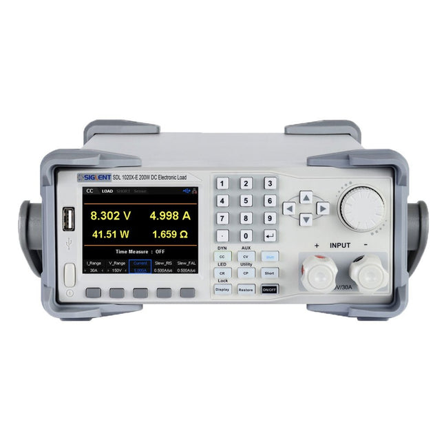
The Siglent SDL1020X-E DC Load leads with measurement resolution of 0.1 mV/0.1 mA and the base SDL1000X-E series resolution is 1 mV/1 mA and adjustable current rise times from 0.001 A/μs~2.5 A/μs. For remote communication and control, the SDL series includes S232/USB/LAN interface types. The SDL1020X-E delivers stability over a wide range of applications and can meet all kinds of testing requirements. including: Power, battery/handheld device design, industry, LED lighting, automotive electronics, and aerospace.
Features
SDL1020X-E (Single channel): DC 150 V/30 A, total power 200 W
4 static modes / Dynamic mode: CC/CV/CR/CP
CC Dynamic mode: Continuous, pulsed, toggled
CC Dynamic mode: 25 kHz, CP Dynamic mode: 12.5 kHz, CV Dynamic mode: 0.5 Hz
Measuring speed of voltage and current: up to 500 kHz
Adjustable current rise time range: 0.001 A/us~2.5 A/us
Min. readback resolution: 0.1 mV, 0.1 mA
Short-circuit, Battery test, CR-LED mode, and factory test functions
4-wire SENSE compensation mode function
List function supports editing as many as 100 steps
Program function supports 50 groups of steps
OCP, OVP, OPP, OTP and LRV protection
External analog control
Voltage, Current monitoring via 0-10 V
3.5 inch TFT-LCD display, capable of displaying multiple parameters and states simultaneously
Built-in RS232/USB/LAN communication interface, USB-GPIB module (optional)
Waveform trend chart and easy-to-use file storage and call functions
Includes PC software: Supports SCPI, LabView driver
Included
1x Siglent SDL1020X-E DC Programmable Load
1x Quick start guide
1x Guarantee Card
1x Power Cord
1x USB Cable
Downloads
Datasheet
Manual
Programming Guide
PC Software
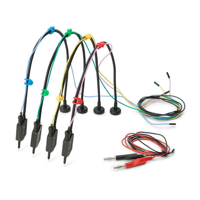
The SQ series of handsfree PCBite probes from Sensepeek are insulated, come with included color-coded cable holders and have a lower point of gravity making them even more stable compared with the original SP series of probes. All the loved features of handsfree measurement, exchangeable fine pitch spring tipped test needle and the minimalistic design is maintained to make traditional sized and handheld probes obsolete.
Features
All handsfree probes from Sensepeek makes instant measurements or long triggering sessions a breeze.
No more soldering wires to connect your probe or complicated tools to setup, just positioning the probe needle on any test point or component in the signal path and release.
Saves time and frustration during development, verification and repairs.
The minimalist design and the spring-loaded test needle makes it possible to simultaneously measure on fine pitch components and nearby signals.
Both length and weight of the SQ probes are perfectly balanced to be used with PCBite PCB holders and base plate which is a must for handsfree function.
The probe holder comes with a powerful magnet in the base, as for all PCBite probes and holders which makes the probe easy to place and reposition.
The SQ series of probes can be used handheld without the probe holder as they have an insulated grip but their full potential is used when measuring handsfree.
Included
4x SQ10 probes and pin tipped test needles (black)
2x Banana to dupont test wires (red/black)
5x Dupont to dupont test wires
1x Set of cable holders (4 colors)
4x Extra test needles
Downloads
User guide
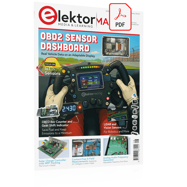
Elektor GREEN and GOLD members can download their digital edition here.
Not a member yet? Click here.
OBD2 Sensor DashboardOld Dials Sparked a Quest for Real Data
OBD2: Add a Rev Counter and Gear Shift Indicator to Your CarRetro, but Super Useful
LiDAR and Vision Sensors for Robotics
Sensor+Test 2025 and PCIM 2025
Contact-Free E-Field Measurements (1)A Vibrating Membrane for Assessing DC Voltages or Static Electric Fields
Wireless Mailbox NotifierFrom Optical Sensors to Radar, Exploring a Few Options
Elektor Mini-WheelieA Self-Balancing Robot
Solar CellsPeculiar Parts, the Series
Getting Started With a Modern Radar SensorIs an Accurate Measurement on Your Radar?
From Life’s ExperiencePaper Factory
CybersecurityTough Times for Hackers
Siglent Presents Next-Gen Multi-Channel OscilloscopesHigh-Performance Solutions for Modern Power and Embedded Systems
Bluetooth 6.0 Brings Enhanced Distance-Ranging ApplicationsNew Version Offers Improved Device Positioning and Location Services
Exploring Wireless Communication with BeagleY-AI
Err-lectronicsCorrections, Updates, and Readers’ Letters
Starting Out in Electronics……Concludes the Topic on Opamps
A Powerful AI Code AssistantSpeed Up Your Development with Continue and Visual Studio Code
Solar Charge Controller with MPPT (2)The Circuit
Ultrasonic Obstacle DetectorA Simple Project to Help Those with Impaired Vision
2025: An AI OdysseyMid-Year Review
Raspberry Pi Standalone MIDI Synthesizer (3)Making It Smarter and Adding a User Interface
Meshtastic: A Demo ProjectAn Intelligent Mesh of LoRa Radios
Analog Audio Frequency GeneratorHigh-Quality Adjustable Frequency Sine Wave Generator
Das Audio-Sonderheft wendet sich an alle, die in der Ausbildung oder im Beruf Audiogeräte (mit Halbleitern und Röhren sowie Lautsprecherboxen) entwickeln und herstellen. Nicht zuletzt vermittelt dieses Elektor-Special auch dem ambitionierten Amateur, Audioliebhaber und Selbstbauer wertvolles Wissen. Es werden u.a. 8 Verstärker und 8 Lautsprecherboxen für den Selbstbau vorgestellt.
Elektor GREEN en GOLD leden kunnen deze uitgave hier downloaden.
Nog geen lid? Klik hier om een lidmaatschap af te sluiten.
OBD2-sensordashboardOude meters vormden het startpunt van een zoektocht naar echte gegevens
OBD2: voeg een toerenteller en schakelindicator toe aan je autoRetro, maar uiterst nuttig
LiDAR- en Visiesensoren voor Robotica
Sensor+Test 2025 en PCIM 2025
Contactloze E-Veldmetingen (1)Een Trillende Membraan voor het Detecteren van Gelijkspanningen of Statische Elektrische Velden
Draadloze brievenbusmeldervan optische sensoren tot radar: enkele mogelijkheden
Elektor Mini-Wheelieeen zelfbalancerende robot
ZonnecellenVreemde onderdelen, de serie
Aan de slag met een moderne radarsensorStaat een nauwkeurige meting op uw radar?
Uit het leven gegrepenpapierfabriek
CybersecurityZware tijden voor hackers
Infographics: IoT en sensoren 2025
Bluetooth 6.0 brengt verbeterde toepassingen voor afstandsbepalingNieuwe versie biedt betere apparaatpositionerings- en -locatieservices
Draadloze communicatie verkennen met BeagleY-AI
Err-lectronicsCorrecties, updates en lezerspost
Alle begin......sluit het thema opamps af
Een krachtige AI-codeerassistentsneller ontwikkelen met Continue en Visual Studio Code
Zonne-laadregelaar met MPPT (2)Het schema
Ultrasone obstakeldetectoreen eenvoudig project om slechtzienden te helpen
2025: Een AI-odysseeHalfjaaroverzicht
Raspberry Pi Standalone MIDI-synthesizer (3)Het slimmer maken en een gebruikersinterface toevoegen
Meshtastic: een demonstratieprojectEen slim netwerk van LoRa-radio's
Analoge audio-frequentiegeneratorHoogwaardige sinusgenerator met instelbare frequentie
MOTORSTEUERUNG MIT H-BRÜCKENFür DC-, Schritt- und bürstenlose Motoren
DAS TEAM IM ELEKTOR-LABORUnser Ansatz, unsere bevorzugten Werkzeuge und mehr
RASPBERRY PI ALS KVM-FERNSTEUERUNGDie Software Pi-KVM im Elektor-Labor-Test
REVIEW: IQAUDIO CODEC ZEROEine Soundkarte für die Raspberry Pi Familie
DAS PIKVM-PROJEKT UND SEINE LEHRENEin Interview mit Maxim Devaev* (Entwickler von PiKVM)
AUTONOMES FAHRZEUG MIT 2D-LIDARESP32 Pico interpretiert die Daten des Lidar-Moduls
RASPBERRY PI ZERO 2 WEin erfreuliches und notwendiges Update
IMPRESSIONEN VOM WORLD ETHICAL ELECTRONICS FORUM 2021
MOTORSTEUERUNGWie die Motorsteuerung weniger kompliziert wird
GRÖSSERE ELEKTROMOTOREPrinzipien und Wissenswertes
ESP32-C3: 32-BIT-RISC-EINKERNEREin erstes Hands-on im Elektor-Labor
SCHÜTZEN SIE SICH SELBST UND ANDERE!Hauptnetzschalter für den Labortisch selbst gebaut
PROGRAMMIEREN IN PYTHONNickname-Generator mit grafischer Benutzeroberfläche
PRODUCTRONICA FAST FORWARD AWARD 2021: DIE PREISTRÄGER
VIELSEITIGER SERVO-TESTERServos ohne Datenblatt analysieren
MODBUS ÜBER WLANTeil 2: Software für das Modbus-TCP-WLAN-Modul
NEURONEN IN NEURONALEN NETZEN VERSTEHENTeil 3: Praktische Neuronen
IM INNEREN EINES OPEN-SOURCE-PROZESSORSEin Beispiel-Kapitel: Lattice- und Xilinx-FPGAs im Vergleich
ALLER ANFANG ...muss nicht schwer sein: Die Spule lässt uns nicht los!
PROJEKT 2.0Korrekturen, Updates und Leserbriefe
COLOR TO SOUNDWie man einen Farbsensor über I2C ausliest
BATTLAB ONEBetriebsdauer von batteriebetriebenen Geräten messen und optimieren!
EINFACHER ERDSCHLUSSPRÜFERIsolationstester für Netzspannungsinstallationen
ARMUT UND ELEKTRONIK1. Ziel für nachhaltige Entwicklung
HEXADOKUThe Original Elektorized Sudoku
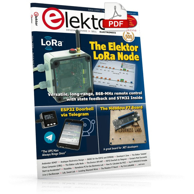
The Elektor LoRa NodeVersatile, long-range, 868-MHz remote control with state feedback and STM32 Inside
InteractiveCorrections & Updates || Questions & Answers
Analogue Electronics DesignCase Study #1 — Section 2: Preamplifier optimized for MEMS microphone
My IoT Button: A Button for the WebPart 1: IoT architecture
BASIC for the ESP32 and ESP8266Programming with Annex WiFi RDS
ESP32 Doorbell via Telegram“The UPS Man Always Rings Once”
Small Circuits RevivalCapita Selecta from the Elektor Project Suggestions Box
My First LoRaWANWith Blue Pill, LoRa Breakout Board and The Things Network
Elektor Connexions 2003EL
“A Strong Supporter of Open Internet”Interview with Wienke Giezeman, Initiator of The Things Network
The Meadow F7 BoardA great board for .NET developers
Practical ESP32 Multitasking (2)Task priorities
Sigfox and the IoT (3)First steps on the network
Raspberry Pi Bash Command Cheat Sheet
Europe's Most Successful Start-up Accelerator?HighTechXL, Eindhoven, The Netherlands
Review: The Enviro+ RPi-HATMeasure air quality with a Raspberry Pi and the Enviro+ HAT
Steeped in Electronicsordering components from Ukraine and Russia
Review: Andonstar AD407Better than its predecessor?
Lab, Sweet LabA glimpse of The Holy Place — no unauthorized entry.
Optical Probe for OscilloscopesMeasure brightness fluctuations of lighting systems
The 'TABULA' Project - An UpdateTangibles with user feedback
How-To Calculate the Prospective Short-Circuit Current or PSCCand choose the proper circuit breaker
TMS1000 Series Microcontrollers
Peculiar Parts, the series
Starting Out in Electronics (2)
Easier than imagined!
Developer's ZoneTips & Tricks, Best Practices and Other Useful Information
Locating Wayward Wires
Track and trace concealed and defective cables with ease and certainty
Review: Joy-IT DMSO2D72 Portable 3-in-1 Oscilloscope
Homebrew PC for the Electronics LabTips on Component Choice and Construction
The Elektor ‘Intelekt’ Chess Computer (1981)Tiny Chess 86 ported to the Intel 8088
Beyond ElectronicsPCB Art - Pushing the Limits of Industrial Manufacturing