
Search results for "all or new or pro or tech or toolkit"
-

Elektor Digital Retrotronica (E-book)
50 maal 'elektronica van vroeger'. In het januarinummer 2005 van het elektronica-maandblad Elektor zag de rubriek 'Retrotronica' voor het eerst het licht. Onder supervisie van Elektor-redacteur Jan Buiting wordt sindsdien elke maand een stukje 'elektronica van vroeger' opgerakeld. Tegenwoordig worden de meeste elektronische schakelingen opgebouwd rond een microcontroller die het 'denkwerk' voor zijn rekening neemt. Nog niet zo heel lang geleden echter bestonden die dingen nog niet (of waren ze onbetaalbaar); niettemin slaagden de ontwerpers van toen er (naar huidige maatstaven) verbijsterend goed in om uiterst betrouwbaar en nauwkeurig werkende schakelingen en apparatuur te bouwen. Veel apparaten blijken, na jaren op een stoffige zolder of in een vochtige kelder te hebben gestaan, na een schoonmaakactie nog perfect te functioneren -- er is dus geen reden om de 'elektronica van vroeger' met een meewarige blik te bekijken; integendeel: het zijn vaak wondertjes van vernuft en vakmanschap! In dit boek hebben we 50 bijdragen uit de rubriek 'Retrotronica' voor u gebundeld - een must voor iedereen die geïnteresseerd is in 'oude' elektronica of in de geschiedenis van het maandblad Elektor (destijds Elektuur), aangezien enkele 'klassieke' Elektuur-schakelingen prominent aan bod komen!
€ 19,95
Members: € 17,96
-

Elektor Digital Basiskurs Elektronik (E-book)
Basiskurs Elektronik (E-book)
€ 24,90
Members: € 22,41
-
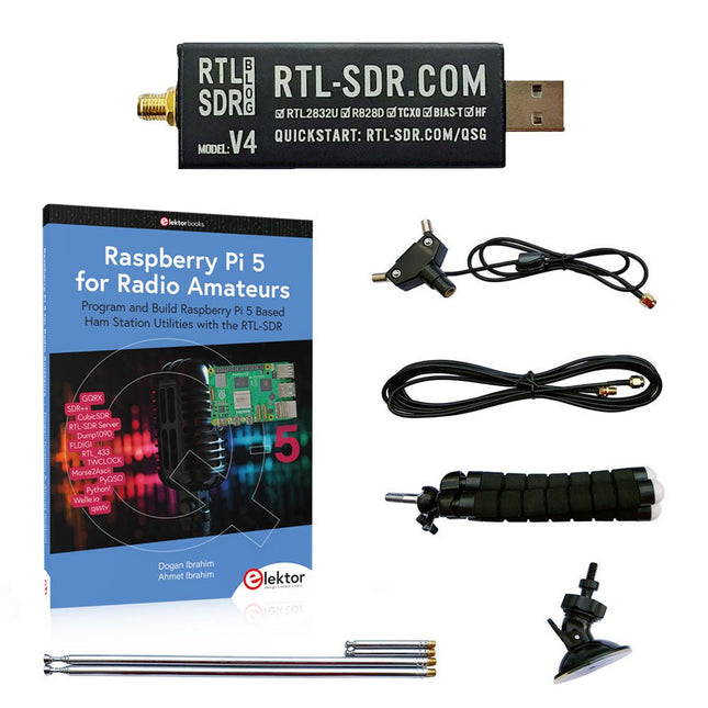
Elektor Bundles Raspberry Pi 5 RTL-SDR V4 (Bundle)
Program and build Raspberry Pi based ham station utilities, tools, and instruments The improved RTL-SDR V4 allows you to receive radio signals between 500 kHz and 1.75 GHz from stations utilizing different bands including MW/SW/LW broadcast, ham radio, utility, air traffic control, PMR, SRD, ISM, CB, weather satellite, and radio astronomy. The book Raspberry Pi 5 for Radio Amateurs gives extensive coverage of deploying the RTL-SDR kit through the use of a Raspberry Pi 5. This bundle contains: RTL-SDR V4 (incl. Dipole Antenna Kit) (normal price: €75) Raspberry Pi 5 for Radio Amateurs (normal price: €40) RTL-SDR V4 (Software Defined Radio) with Dipole Antenna Kit RTL-SDR is an affordable dongle that can be used as a computer-based radio scanner for receiving live radio signals between 500 kHz and 1.75 GHz in your area. The RTL-SDR V4 offers several improvements over generic brands including use of the R828D tuner chip, triplexed input filter, notch filter, improved component tolerances, a 1 PPM temperature compensated oscillator (TCXO), SMA F connector, aluminium case with passive cooling, bias tee circuit, improved power supply, and a built in HF upconverter. RTL-SDR V4 comes with the portable dipole antenna kit. It is great for beginners as it allows for terrestrial and satellite reception and easy to mount outdoors and designed for portable and temporary outside usage. Features Improved HF reception: V4 now uses a built-in upconverter instead of using a direct sampling circuit. This means no more Nyquist folding of signals around 14.4 MHz, improved sensitivity, and adjustable gain on HF. Like the V3, the lower tuning range remains at 500 kHz and very strong reception may still require front end attenuation/filtering. Improved filtering: The V4 makes use of the R828D tuner chip, which has three inputs. The SMA input has been triplexed input into 3 bands: HF, VHF and UHF. This provides some isolation between the 3 bands, meaning out of band interference from strong broadcast stations is less likely to cause desensitization or imaging. Improved filtering x2: In addition to the triplexing, the open drain pin on the R828D can be also used, which allows to add simple notch filters for common interference bands such as broadcast AM, broadcast FM and the DAB bands. These only attenuate by a few dB, but may still help. Improved phase noise on strong signals: Due to an improved power supply design, phase noise from power supply noise has been significantly reduced. Less heat: Another advantage of the improved power supply is low power consumption and less heat generation compared to the V3. Included 1x RTL-SDR V4 dongle (R828D RTL2832U 1PPM TCXO SMA) 2x 23 cm to 1 m telescopic antenna 2x 5 cm to 13 cm telescopic antenna 1x Dipole antenna base with 60 cm RG174 1x 3 m RG174 extension cable 1x Flexible tripod mount 1x Suction cup mount Downloads Datasheet User Guide Quick Start Guide SDR# User Guide Dipole Antenna Guide Book: Raspberry Pi 5 for Radio Amateurs The RTL-SDR devices (V3 and V4) have gained popularity among radio amateurs because of their very low cost and rich features. A basic system may consist of a USB based RTL-SDR device (dongle) with a suitable antenna, a Raspberry Pi 5 computer, a USB based external audio input-output adapter, and software installed on the Raspberry Pi 5 computer. With such a modest setup, it is possible to receive signals from around 24 MHz to over 1.7 GHz. This book is aimed at amateur radio enthusiasts and electronic engineering students, as well as at anyone interested in learning to use the Raspberry Pi 5 to build electronic projects. The book is suitable for both beginners through experienced readers. Some knowledge of the Python programming language is required to understand and eventually modify the projects given in the book. A block diagram, a circuit diagram, and a complete Python program listing is given for each project, alongside a comprehensive description. The following popular RTL-SDR programs are discussed in detail, aided by step-by-step installation guides for practical use on a Raspberry Pi 5: SimpleFM GQRX SDR++ CubicSDR RTL-SDR Server Dump1090 FLDIGI Quick RTL_433 aldo xcwcp GPredict TWCLOCK CQRLOG klog Morse2Ascii PyQSO Welle.io Ham Clock CHIRP xastir qsstv flrig XyGrib FreeDV Qtel (EchoLink) XDX (DX-Cluster) WSJT-X The application of the Python programming language on the latest Raspberry Pi 5 platform precludes the use of the programs in the book from working on older versions of Raspberry Pi computers.
-

QuantAsylum QuantAsylum QA403 24-bit Audio Analyzer
The QA403 is QuantAsylum's fourth-generation audio analyzer. The QA403 extends the functionality of the QA402 with improved noise and distortion performance, in addition to a flatter response at band edges. The compact size of the QA403 means you can take it just about anywhere. Features 24-bit ADC/DAC Up to 192 kS/s Fully isolated from PC Differential Input/Output USB powered Built-in Attenuator Fast Bootup and Driverless The QA403 is a driverless USB device, meaning it’s ready as soon as you plug it in. The software is free and it is quick and easy to move the hardware from one machine to the next. So, if you need to head to the factory to troubleshoot a problem or take the QA403 home for a work-from-home day, you can do it without hassle. No-Cal Design The QA403 comes with a factory calibration in its flash memory, ensuring consistent unit-to-unit performance. On your manufacturing line you can install another QA403 and be confident what you read on one unit will be very similar to the next unit. It is not expected that re-calibration will be required at regular intervals. Measurements Making basic measurements is quick and easy. In a few clicks you will understand the frequency response, THD(+N), gain, SNR and more of your device-under test. Dynamic Range The QA403 offers 8 gain ranges on the input (0 to +42 dBV in 6 steps), and 4 gain ranges on the output (-12 to +18 dBV in 10 dB steps). This ensures consistent performance over very wide ranges of input and output levels. The maximum AC input to the QA403 is +32 dBV = 40 Vrms. The maximum DC is ±40 V, and the maximum ACPEAK + DC = ±56 V. Easy Programmability The QA403 supports a REST interface, making it easy to automate measurements in just about any language you might anticipate. From Python to C++ to Visual Basic—if you know how to load a web page in your favorite language, you can control the QA403 remotely. Measurements are fast and responsive, usually with dozens of commands being processed per second. Isolated and USB Powered The QA403 is isolated from the PC, meaning you are measuring your DUT and not chasing some phantom ground loop. The QA403 is USB powered, like nearly all our instruments. If you are setting up remotely, throw a powered hub in your bag and your entire test setup can be running with a minimum of cables. Goodbye Soundcard, Hello QA403 Tired of trying to make a soundcard work? The calibration nightmare? The lack of gain stages? The limited drive? Are you tired of dealing with the fixed input ranges? The worry that you might destroy it with too much DC or AC? Tired of the ground loops? That’s why QuantAsylum built the QA403. Specifications Case Material Powder-coating Aluminum (2 mm thick front panel, 1.6 mm thick top/bottom) Dimensions 177 x 44 x 97 mm (W x H x D) Weight 435 g Downloads Datasheet Manual GitHub
-
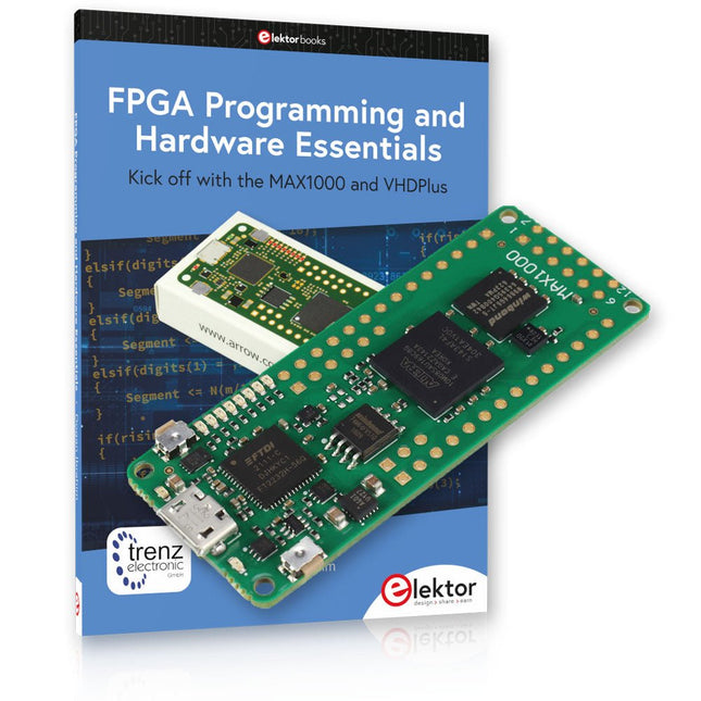
Elektor Bundles MAX1000 FPGA Programming Bundle
Kick off to FPGA Programming with the MAX1000 Board and VHDPlus Ready to master FPGA programming? With this bundle, you'll dive into the world of Field-Programmable Gate Arrays (FPGAs) – a configurable integrated circuit that can be programmed after manufacturing. Bring your ideas to life, from simple projects to complete microcontroller systems! The MAX1000 is a compact and powerful FPGA development board packed with features like memory, user LEDs, push-buttons, and flexible I/O ports. It’s the ideal starting point for anyone wanting to learn about FPGAs and Hardware Description Languages (HDLs). With the enclosed book "FPGA Programming and Hardware Essentials" you'll get hands-on with the VHDPlus programming language – a simpler version of VHDL. You'll work on practical projects using the MAX1000, helping you gain the skills and confidence to unleash your creativity. Projects in the Book Arduino-driven BCD to 7-Segment Display Decoder Use an Arduino Uno R4 to supply BCD data to the decoder, counting from 0 to 9 with a one-second delay Multiplexed 4-Digit Event Counter Create an event counter that displays the total count on a 4-digit display, incrementing with each button press PWM Waveform with Fixed Duty Cycle Generate a PWM waveform at 1 kHz with a fixed duty cycle of 50% Ultrasonic Distance Measurement Measure distances using an ultrasonic sensor, displaying the results on a 4-digit 7-segment LED Electronic Lock Build a simple electronic lock using combinational logic gates with push buttons and an LED output Temperature Sensor Monitor ambient temperature with a TMP36 sensor and display the readings on a 7-segment LED MAX1000 FPGA Development Board The MAX1000 is a customizable IoT/Maker Board ready for evaluation, development and/or use in a product. It is built around the Intel MAX10 FPGA, which is the industry’s first single chip, non-volatile programmable logic device (PLDs) to integrate the optimal set of system components. Users can now leverage the power of tremendous re-configurability paired with a high-performance, low-power FPGA system. Providing internally stored dual images with self-configuration, comprehensive design protection features, integrated ADCs and hardware to implement the Nios II 32-bit microcontroller IP, MAX10 devices are ideal solution for system management, protocol bridging, communication control planes, industrial, automotive and consumer applications. The MAX1000 is equipped with an Arrow USB Programmer2, SDRAM, flash memory, accelerometer sensor and PMOD/Arduino MKR connectors making it a fully featured plug and play solution without any additional costs. Specifications MAX 10 8 kLE - Flash Dual inside - ADC 8x 12 Bit - Temperature Range 0~85°C - Supply USB/pins SDRAM 8 MB 3-axis MEMS LIS3DH USB Programmer on board MEMS Oscillator 12 MHz Switch/LED 2x / 8x Contents of the Bundle Book: FPGA Programming and Hardware Essentials (normal price: €40) MAX1000 FPGA Development Board (normal price: €45) Downloads Software
-

Elektor 09-10/2025 (DE)
Diese Ausgabe steht allen GOLD- und GREEN-Mitgliedern auf der ElektorMagazine-Website zum Download bereit! Sie sind noch kein Mitglied? Hier klicken! ESP32-Audio-Transceiver-Board (Teil 2)Drahtlose Audioübertragung Induktiver AM-SenderPIO des Pico in einem Arduino-Sketch Navigieren durch drahtlose ProtokolleEin technischer Leitfaden Satellitenverfolgung mit LoRaDas TinyGS-Netzwerk: Raumfahrtdaten gelangen zur Erde 4G-kompatible SMS-FernbedienungSteuern Sie Ihr Zuhause per Telefon aus der Ferne Hochgeschwindigkeits-TastkopfHochohmige Eingänge für Signale bis 200 MHz Aus dem Leben gegriffenKafka KrakenSDREin phasenkohärenter SDR-Empfänger Geschwindigkeitstests mit dem RP2350Lohnt sich der Umstieg von Raspberry Pi Pico 1 auf Version 2? Kontaktlose E-Feld-Messungen (2)Ein Laser-Vibrometer zur Erfassung der Membranschwingungen Quarze und OszillatorenQuarzgenauigkeit durch die Kondensatorwahl verbessern Aller Anfang ...... ist gar nicht schwer: Spezielle Audio-ICs Einstieg ins Programmieren von Selbstbauprojekten SPECTRAN® V6 MobileModular konfigurierbarer Echtzeit-Spektrum-Analyzer für zuverlässige Messungen in allen Frequenzbereichen Die Zukunft der KI wird in Silizium geschmiedetEin Interview mit Anastasiia Nosova Autonomer Sensorknoten v2.0 (Systemarchitektur)Solarbetriebene Sensorplattform mit integriertem GPS, LoRaWAN und weiteren Funktionen Präzise PositionsbestimmungBluetooth Channel Sounding ausprobiert Die Zukunft der Wireless-KommunikationDie ultradünnen Festkörperbatterien von BTRY Testgetriebene Programmierung in der Firmware-Entwicklung Handy-gesteuertes ModellautoWLAN + ESP32 + Smartphone = Fernsteuerung 2025: Eine KI-OdysseeKI-Denkmodelle: die Gedankenketten-Revolution Solarladeregler mit MPP-TrackingTeil 3: Software und Inbetriebnahme Web-Streaming-Kamera mit Raspberry Pi ZeroVerwendung des ZeroTier-VPN
€ 15,90


