
Search results for "red OR pitaya OR for OR test OR and OR measurement"
-
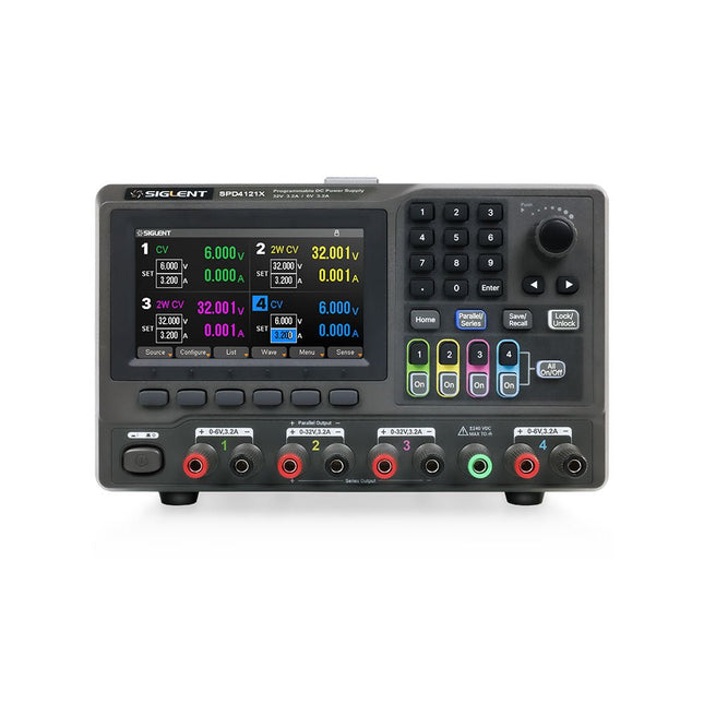
Siglent Siglent SPD4121X 4-ch DC Power Supply (285 W)
The Siglent SPD4121X is a 4-channel DC Linear Programmable Power Supply equipped with a 4.3-inch TFT-LCD display, friendly human-machine interface, and excellent performance indicators. Real-time waveform display provides engineers with an informative user interface. SPD4121X offers a total output power of 285 W with a resolution of 1 mV/1 mA. The maximum voltage and current for each channel are as follows: CH1: 15 V/1.5 A CH2: 12 V/10 A CH3: 12 V/10 A CH4: 15 V/1.5 A Features Rated output power: 285 W Rated voltage: 32 V, 12 V, 30 V Up to four high-precision power supplies with independent controllable outputs, supporting CH2 and CH3 series and parallel connections Clear graphical interface with waveform and timer display modes 5-digit voltage and current display with minimum resolution of 1 mV, 1 mA Fast output response time: <50us The high current channel support remote voltage compensation sense function. The maximum compensation voltage is 0.6 V Overvoltage protection and overcurrent protection or safe and accurate operation Equipped with a 4.3-inch TFT-LCD display (480 x 272 resolution) USB and LAN standard communication USB-GPIB module is optional Excellent channel density with up to 4 channels in a 3U half rack package Internal data storage for setups and parameters Embedded Web Server with instrument communication that doesn’t require software installation Fully SCPI programming command set support as well as a LabView driver for remote control and system automation Specifications SPD4323X SPD4121X SPD4306X Channel Output CH1: Voltage 0 to 6 V Current 0 to 3.2 ACH2: Voltage 0 to 32 V Current 0 to 3.2 ACH3: Voltage 0 to 32 V Current 0 to 3.2 ACH4: Voltage 0 to 6 V Current 0 to 3.2 A CH1: Voltage 0 to 15 V Current 0 to 1.5 ACH2: Voltage 0 to 12 V Current 0 to 10 ACH3: Voltage 0 to 12 V Current 0 to 10 ACH4: Voltage 0 to 15 V Current 0 to 1.5 A CH1: Voltage 0 to 15 V Current 0 to 1.5 ACH2: Voltage 0 to 30 V Current 0 to 6 ACH3: Voltage 0 to 30 V Current 0 to 6 ACH4: Voltage 0 to 15 V Current 0 to 1 A Resolution 1 mV, 1 mA 1 mV, 1 mA 1 mV, 1 mA Setting Accuracy Voltage: ±(0.03% of reading+10) mV, Current: ±(0.3% of reading+10) mA Voltage: ±(0.03% of reading+10) mV, Current: ±(0.3% of reading+10) mA Voltage: ±(0.03% of reading+10) mV, Current: ±(0.3% of reading+10) mA Readback Accuracy Voltage: ±(0.03% of reading+10) mV, Current: ±(0.3% of reading+10) mA Voltage: ±(0.03% of reading+10) mV, Current: ±(0.3% of reading+10) mA Voltage: ±(0.03% of reading+10) mV, Current: ±(0.3% of reading+10) mA Display 4.3" TFT-LCD 5-digit voltage and current display 4.3" TFT-LCD 5-digit voltage and current display 4.3" TFT-LCD 5-digit voltage and current display Output power 240 W 285 W 400 W Included 1x Siglent SPD4121X Power Supply 1x Power cord (EU) 1x Output test cord (3 A) 1x USB cable 1x Quick start guide Downloads Datasheet Manual Quick start
€ 871,20
-

Elektor Digital Retronics (E-book)
Quite unintentionally a one-page story on an old Heathkit tube tester in the December 2004 edition of Elektor magazine spawned dozens of ‘Retronics’ tales appearing with a monthly cadence, and attracting a steady flow of reader feedback and contributions to the series. Since launching his Retronics columns, Elektor Editor Jan Buiting has never been short of copy to print, or vintage equipment to marvel at. This book is a compilation of about 80 Retronics installments published between 2004 and 2012. The stories cover vintage test equipment, prehistoric computers, long forgotten components, and Elektor blockbuster projects, all aiming to make engineers smile, sit up, object, drool, or experience a whiff of nostalgia. To reflect that our memories are constantly playing tricks on us, and honoring that “one man’s rubbish is another man’s gem”, the tales in the book purposely have no chronological order, and no bias in favor of transistor or tube, microprocessor or discrete part, audio or RF, DIY or professional, dry or narrative style. Although vastly diff erent in subject matter, all tales in the book are told with personal gusto because Retronics is about sentiment in electronics engineering, construction and repair, be it to reminisce about a 1960s Tektronix scope with a cleaning lady as a feature, or a 1928 PanSanitor box for dubious medical use. Owners of this book are advised to not exceed one Retronics tale per working day, preferably consumed in the evening hours under lamp light, in a comfortable chair, with a piece of vintage electronic equipment close and powered up.
€ 24,95
Members: € 22,46
-
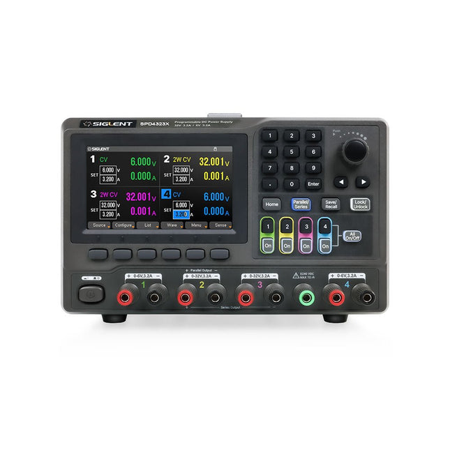
Siglent Siglent SPD4323X 4-ch DC Power Supply (240 W)
The Siglent SPD4323X is a 4-channel DC Linear Programmable Power Supply equipped with a 4.3-inch TFT-LCD display, friendly human-machine interface, and excellent performance indicators. Real-time waveform display provides engineers with an informative user interface. SPD4323X offers a total output power of 240 W with a resolution of 1 mV/1 mA. The maximum voltage and current for each channel are as follows: CH1: 6 V/3.2 A CH2: 32 V/3.2 A CH3: 32 V/3.2 A CH4: 6 V/3.2 A Features Rated output power: 240 W Rated voltage: 32 V, 12 V, 30 V Up to four high-precision power supplies with independent controllable outputs, supporting CH2 and CH3 series and parallel connections Clear graphical interface with waveform and timer display modes 5-digit voltage and current display with minimum resolution of 1 mV, 1 mA Fast output response time: <50us The high current channel support remote voltage compensation sense function. The maximum compensation voltage is 0.6 V Overvoltage protection and overcurrent protection or safe and accurate operation Equipped with a 4.3-inch TFT-LCD display (480 x 272 resolution) USB and LAN standard communication USB-GPIB module is optional Excellent channel density with up to 4 channels in a 3U half rack package Internal data storage for setups and parameters Embedded Web Server with instrument communication that doesn’t require software installation Fully SCPI programming command set support as well as a LabView driver for remote control and system automation Specifications SPD4323X SPD4121X SPD4306X Channel Output CH1: Voltage 0 to 6 V Current 0 to 3.2 ACH2: Voltage 0 to 32 V Current 0 to 3.2 ACH3: Voltage 0 to 32 V Current 0 to 3.2 ACH4: Voltage 0 to 6 V Current 0 to 3.2 A CH1: Voltage 0 to 15 V Current 0 to 1.5 ACH2: Voltage 0 to 12 V Current 0 to 10 ACH3: Voltage 0 to 12 V Current 0 to 10 ACH4: Voltage 0 to 15 V Current 0 to 1.5 A CH1: Voltage 0 to 15 V Current 0 to 1.5 ACH2: Voltage 0 to 30 V Current 0 to 6 ACH3: Voltage 0 to 30 V Current 0 to 6 ACH4: Voltage 0 to 15 V Current 0 to 1 A Resolution 1 mV, 1 mA 1 mV, 1 mA 1 mV, 1 mA Setting Accuracy Voltage: ±(0.03% of reading+10) mV, Current: ±(0.3% of reading+10) mA Voltage: ±(0.03% of reading+10) mV, Current: ±(0.3% of reading+10) mA Voltage: ±(0.03% of reading+10) mV, Current: ±(0.3% of reading+10) mA Readback Accuracy Voltage: ±(0.03% of reading+10) mV, Current: ±(0.3% of reading+10) mA Voltage: ±(0.03% of reading+10) mV, Current: ±(0.3% of reading+10) mA Voltage: ±(0.03% of reading+10) mV, Current: ±(0.3% of reading+10) mA Display 4.3" TFT-LCD 5-digit voltage and current display 4.3" TFT-LCD 5-digit voltage and current display 4.3" TFT-LCD 5-digit voltage and current display Output power 240 W 285 W 400 W Included 1x Siglent SPD4323X Power Supply 1x Power cord (EU) 1x Output test cord (3 A) 1x USB cable 1x Quick start guide Downloads Datasheet Manual Quick start
€ 762,30
-

BusBoard BreadBoard BB830T (830 Tie Points) Transparent
The BB830T is a solderless (plug-in) transparent breadboard with 830 connection tie-points (i.e. 830 wire insertion holes). It has 4 power rails. Solderless breadboards are great for building and testing new circuits because parts can be easily inserted and removed. They are completely re-usable. The BB830T has a 630 tie-point IC-circuit area plus four 50 tie-point power rails. Specifications 830 tie points total: 630 tie-point IC-circuit area plus two 100 tie-point distribution strips providing 4 power rails. ABS plastic/transparent body with black printed legend. Color legend on distribution strips. Contacts are Phosphor Bronze with Plated Nickel Finish, rated for 50,000 insertions. Rated at 36 Volts, 2 Amps. Insertion Wire Size is 21 to 26 AWG, 0.016 to 0.028 inches diameter (0.4 to 0.7mm diameter). Peelable adhesive tape backing provided for attaching to a surface. Metal back plate provided.
€ 10,29
-

FNIRSI FNIRSI TMP-610S (3-in-1) Multimeter (60,000 Counts) + Oscilloscope + Signal Generator
The FNIRSI TMP-610S is a compact 3-in-1 test instrument combining a True RMS multimeter, 10 MHz oscilloscope, and 50 kHz DDS signal generator. It is designed for electronics troubleshooting, circuit testing, and development in the lab or on the go. The multimeter offers 60,000-count resolution and supports voltage, current, resistance, capacitance, frequency, temperature, diode, and continuity measurements. The integrated oscilloscope provides real-time waveform analysis at up to 48 MSa/s, while the signal generator supports 13 waveform types with adjustable frequency, amplitude, and duty cycle. A 3.5-inch IPS touchscreen, smart auto-scan, Bluetooth connectivity for DMM functions, waveform storage, USB export, and a 3,000 mAh rechargeable battery make the TMP-610S a versatile all-in-one tool for electronics professionals and enthusiasts. Features 3-in-1 Design: DMM + Oscilloscope + Signal Generator 60,000-Count True RMS High-Precision Measurement 10 MHz Oscilloscope with 48 MSa/s Sampling Rate Bluetooth App Sync (Multimeter Function Only) 3.5-inch Smart Touchscreen with Multiple Display Modes 50 kHz DDS Signal Generator with 13 Waveforms Built-in Fuse for Easy Replacement Specifications Multimeter Function Range Accuracy DC voltage 600mV/6V/60V/600V/1000V ±(0.03%+5d) AC voltage 600mV/6V/60V /600V/750V ±(0.3%+15d) DC current 600uA/6000uA/60mA/600mA ±(0.15%+5d) 6A/10A ±(0.2%+5d) AC current 600uA/6000uA/60mA/600mA ±(0.5%+15d) 6A/10A ±(0.75%+15d) Resistance 600Ω/6KΩ/60KΩ/600KΩ/6MΩ ±(0.1%+5d) 60MΩ ±(0.2%+10d) Capacitance 60nF/600nF/6uF/60uF ±(2.5%+30d) 600uF/6mF/60mF ±(3.5%+30d Frequency 10 Hz~60 MHz ±(0.01%+5d) Temperature -40℃~1000℃ ±(1.0%+5℃) Continuity 0Ω~1KΩ ±(0.2%+5d) Diode 0V~3.0V, 0Ω~1 Ω ±(1%+5d) AC frequency response 10KHz / Oscilloscope Real-time Sampling Rate 48 MSa/s Analog Bandwidth 10 MHz Input Impedance 1MΩ Coupling Mode AC/DC Test Voltage Range 1:1 Probe - 80Vpp (±40V) 10:1 Probe - 800Vpp (±400V) Vertical Sensitivity 10mV/div~10V/div Vertical Displacement Adjustable with indication Horizontal Time Base Range 50 ns ~ 20 s Trigger Mode Auto, Normal, Single Trigger Type Rising, Falling, 50% Trigger Level Adjustable with indication Measurement Parameters Freq, Period, +Duty, ‒Duty, +Width, ‒Width, Max, Min, P‒P, Amp, RMS, Avg Persistence Off / 500ms / 1s / ∞ Cursor Measurement Yes Waveform Screenshot Saving Yes Signal Generator Output Waveform Supports 13 waveform types Frequency 0~50kHz Amplitude 0.0V~3.0V Duty Cycle 0~100%, adjustable for Square and Sawtooth waves Included 1x FNIRSI TMP-610S Multimeter + Oscilloscope + Signal Generator 1x P6100 Probe 1x Adapter 2x Alligator Clips 2x Multimeter Probes Probe Accessories 1x Storage Bag 1x USB-C Cable 1x Manual Downloads Manual
-
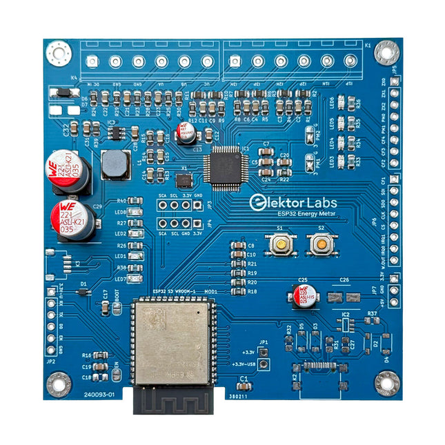
Elektor Labs Elektor ESP32 Energy Meter
The Elektor ESP32 Energy Meter is a device designed for real-time energy monitoring and smart home integration. Powered by the ESP32-S3 microcontroller, it offers robust performance with modular and scalable features. The device uses a 110/230 VAC to 12 VAC step-down transformer for voltage sampling, ensuring galvanic isolation and safety. Its compact PCB layout includes screw-type terminal blocks for secure connections, a Qwiic connector for additional sensors, and a programming header for direct ESP32-S3 configuration. The energy meter is compatible with single-phase and three-phase systems, making it adaptable for various applications. The energy meter is simple to set up and integrates with Home Assistant, offering real-time monitoring, historical analytics, and automation capabilities. It provides accurate measurements of voltage, current, and power, making it a valuable tool for energy management in homes and businesses. Features Comprehensive Energy Monitoring: Get detailed insights into your energy usage for smarter management and cost savings. Customizable Software: Tailor functionality to your needs by programming and integrating custom sensors. Smart Home Ready: Compatible with ESPHome, Home Assistant, and MQTT for full Smart Home integration. Safe & Flexible Design: Operates with a 110/230 VAC to 12 VAC step-down transformer and features a pre-assembled SMD board. Quick Start: Includes one Current Transformer (CT) sensor and access to free setup resources. Specifications Microcontroller ESP32-S3-WROOM-1-N8R2 Energy Metering IC ATM90E32AS Status Indicators 4x LEDs for power consumption indication2x Programmable LEDs for custom status notifications User Input 2x Push buttons for user control Display Output I²C OLED display for real-time power consumption visualization Input Voltage 12~16 VAC (via a step-down transformer 110/230 VAC to 12 VAC) Clamp Current Sensor YHDC SCT013-000 (100 A/50 mA) included Smart Home Integration ESPHome, Home Assistant, and MQTT for seamless connectivity Connectivity Header for programming, Qwiic for sensor expansion Applications Supports single-phase and three-phase energy monitoring systems Dimensions 79.5 x 79.5 mm Included 1x Partly assembled board (SMDs are pre-mounted) 2x Screw terminal block connectors (not mounted) 1x YHDC SCT013-000 current transformer Required Power transformer not included Downloads Datasheet (ESP32-S3-WROOM-1) Datasheet (ATM90E32AS) Datasheet (SCT013-000) Frequently Asked Questions (FAQ) From Prototype to Finished Product What started as an innovative project to create a reliable and user-friendly energy meter using the ESP32-S3 microcontroller has evolved into a robust product. Initially developed as an open-source project, the ESP32 Energy Meter aimed to provide precise energy monitoring, smart home integration and more. Through meticulous hardware and firmware development, the energy meter now stands as a compact, versatile solution for energy management.
-
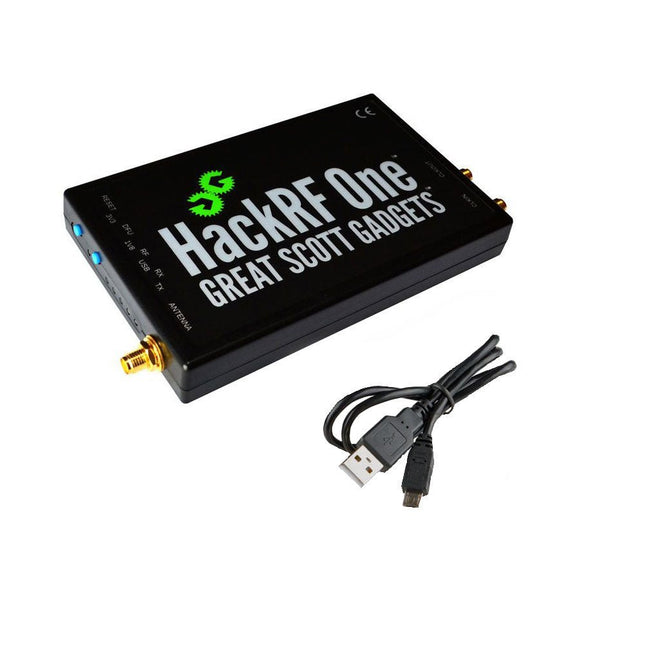
Great Scott Gadgets Great Scott Gadgets HackRF One SDR (1 MHz – 6 GHz)
New Version available! Click here! HackRF One is a Software Defined Radio (SDR) peripheral capable of transmission or reception of radio signals from 1 MHz to 6 GHz. Designed to enable test and development of modern and next generation radio technologies, HackRF One is an open source hardware platform that can be used as a USB peripheral or programmed for stand-alone operation. Specifications 1 MHz to 6 GHz operating frequency Half-duplex transceiver Up to 20 million samples per second 8-bit quadrature samples (8-bit I and 8-bit Q) Compatible with GNU Radio, SDR and more Software-configurable RX and TX gain and baseband filter Software-controlled antenna port power (50 mA at 3.3 V) SMA female antenna connector SMA female clock input and output for synchronization Convenient buttons for programming Internal pin headers for expansion Hi-Speed USB 2.0 USB-powered Open source hardware HackRF One is test equipment for RF systems. It has not been tested for compliance with regulations governing transmission of radio signals. You are responsible for using your HackRF One legally. Included 1x HackRF One SDR 1x Plastic enclosure 1x micro-USB cable Note: An antenna is not included. ANT500 is recommended as a starter antenna for HackRF One. Downloads Documentation GitHub Source code and hardware design files
-

Elektor Labs Elektor Dual DC LISN (150 kHz – 200 MHz)
Measuring conducted emission is the simplest and most affordable method of getting some indication of whether a design can meet EMI/EMC requirements. A Line Impedance Stabilization Network (LISN) is an indispensable part of an EMC pre-compliance test setup. In cooperation with Würth Elektronik, Elektor has developed a 5 µH, 50 Ω Dual DC LISN that supports voltages up to 60 V and currents up to 10 A. The instrument measures RF interferences on both channels (the power supply) by means of 5-μH blocking inductances. The internal 10-dB attenuation network – one in each channel – contains a 3rd-order high-pass filter with a cutoff frequency of 9 kHz to protect the input of instruments like a spectrum analyzer from potentially harmful DC voltages or low frequencies coming from the EUT (Equipment Under Test). Specifications RF path Channels 2 (with clamping diodes) Bandwidth 150 kHz – 200 MHz Inductance 5 μH || 50 Ω Internal attenuation 10 dB Connectors SMA DC path Max. current < 10 ADC Max. voltage < 60 VDC DC resistance < 2 x 70 mΩ PCB size 94.2 x 57.4 mm Connectors 4-mm banana Hammond enclosure Type 1590N Dimensions 121 x 66 x 40 mm Included 1x 4-layer PCB with all SMT parts fitted 1x pre-drilled enclosure with ready-printed front panel layout 5x gold-plated, insulated, 4-mm banana sockets, rated for 24 A, 1 kV 1x Hammond enclosure 1590N1, Aluminum (Die-Cast Alloy) More Info Project on Elektor Labs: Dual DC LISN for EMC pre-compliance testing Elektor 9-10/2021: EMC Pre-Compliance Test for Your DC-Powered Project (Part 1) Elektor 11-12/2021: EMC Pre-Compliance Test for Your DC-Powered Project (Part 2)
-
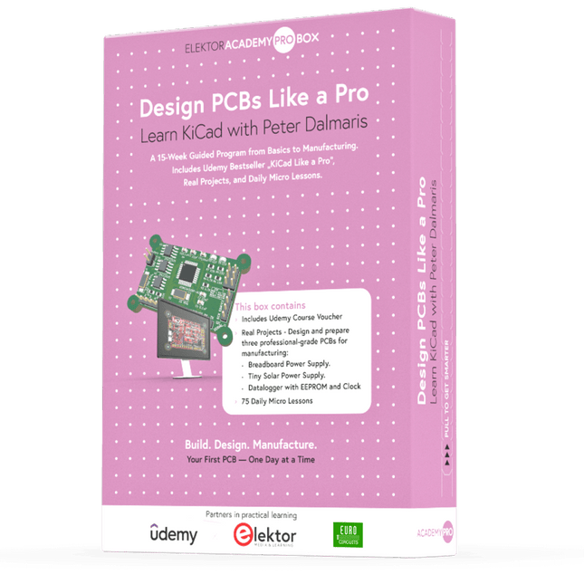
Elektor Academy Pro Design PCBs Like a Pro
Learn KiCad with Peter Dalmaris The Academy Pro Box "Design PCBs like a Pro" offers a complete, structured training programme in PCB design, combining online learning with practical application. Based on Peter Dalmaris’ KiCad course, the 15-week programme integrates video lessons, printed materials (2 books), and hands-on projects to ensure participants not only understand the theory but also develop the skills to apply it in practice. Unlike standard courses, the Academy Pro Box provides a guided learning path with weekly milestones and physical components to design, test, and produce working PCBs. This approach supports a deeper learning experience and better knowledge retention. The box is ideal for engineers, students, and professionals who want to develop practical PCB design expertise using open-source tools. With the added option to have their final project manufactured, participants complete the programme with real results – ready for use, testing, or further development. Learn by doing Build skills. Design real boards. Generate Gerbers. Place your first order. This isn’t just a course – it’s a complete project journey from idea to product. You’ll walk away with: Working knowledge of KiCad’s tools Confidence designing your own PCBs A fully manufacturable circuit board – made by you What's inside the Box (Course)? Both volumes of "KiCad Like a Pro" (valued at €105) Vol 1: Fundamentals and Projects Vol 2: Advanced Projects and Recipes Coupon code to join the bestselling KiCad 9 online course by Peter Dalmaris on Udemy, featuring 20+ hours of video training. You'll complete three full design projects: Breadboard Power Supply Tiny Solar Power Supply Datalogger with EEPROM and Clock Voucher from Eurocircuits for the production of PCBs (worth €85 excl. VAT) Learning Material (of this Box/Course) 15-Week Learning Program ▶ Click here to open Week 1: Setup, Fundamentals, and First Steps in PCB Design Week 2: Starting Your First PCB Project – Schematic Capture Week 3: PCB Layout – From Netlist to Board Design Week 4: Design Principles, Libraries, and Workflow Week 5: Your First Real-World PCB Project Week 6: Custom Libraries – Symbols, Footprints, and Workflow Week 7: Advanced Tools – Net Classes, Rules, Zones, Routing Week 8: Manufacturing Files, BOMs, and PCB Ordering Week 9: Advanced Finishing Techniques – Graphics, Refinement, and Production Quality Week 10: Tiny Solar Power Supply – From Schematic to Layout Week 11: Tiny Solar Power Supply – PCB Layout and Production Prep Week 12: ESP32 Clone Project – Schematic Design and Layout Prep Week 13: ESP32 Clone – PCB Layout and Manufacturing Prep Week 14: Final Improvements and Advanced Features Week 15: Productivity Tools, Simulation, and Automation KiCad Course with 18 Lessons on Udemy (by Peter Dalmaris) ▶ Click here to open Introduction Getting started with PCB design Getting started with KiCad Project: A hands-on tour of KiCad (Schematic Design) Project: A hands-on tour of KiCad (Layout) Design principles and PCB terms Design workflow and considerations Fundamental KiCad how-to: Symbols and Eeschema Fundamental KiCad how-to: Footprints and Pcbnew Project: Design a simple breadboard power supply PCB Project: Tiny Solar Power Supply Project: MCU datalogger with build-in 512K EEPROM and clock Recipes KiCad 9 new features and improvements Legacy (from previous versions of KiCad) KiCad 7 update (Legacy) (Legacy) Gettings started with KiCad Bonus lecture About the Author Dr. Peter Dalmaris, PhD is an educator, an electrical engineer and Maker. Creator of online video courses on DIY electronics and author of several technical books. As a Chief Tech Explorer since 2013 at Tech Explorations, the company he founded in Sydney, Australia, Peter's mission is to explore technology and help educate the world. What is Elektor Academy Pro? Elektor Academy Pro delivers specialized learning solutions designed for professionals, engineering teams, and technical experts in the electronics and embedded systems industry. It enables individuals and organizations to expand their practical knowledge, enhance their skills, and stay ahead of the curve through high-quality resources and hands-on training tools. From real-world projects and expert-led courses to in-depth technical insights, Elektor empowers engineers to tackle today’s electronics and embedded systems challenges. Our educational offerings include Academy Books, Pro Boxes, Webinars, Conferences, and industry-focused B2B magazines – all created with professional development in mind. Whether you're an engineer, R&D specialist, or technical decision-maker, Elektor Academy Pro bridges the gap between theory and practice, helping you master emerging technologies and drive innovation within your organization.
-

Elektor Janvier/Février 2025 (FR)
Le téléchargement intégral de ce numéro est disponible pour nos membres GOLD et GREEN sur le site Elektor Magazine ! Pas encore membre ? Cliquez ici. stockage de l’énergieRéalisez votre propre stockage d’énergie pour réseau de panneaux photovoltaïques simulateur de panneau solaireUne solution pour tester et optimiser les trackers MPP et les onduleurs le concours STM32 Edge AIDécouvrez le STM32N6 et gagnez les 5000 € du concours ! Matériaux à large bande interditePourquoi y a-t-il un tel intérêt pour le SiC et le GaN ? batterie externe pour ordinateur portableProlongez la durée de vie de votre vieil ordinateur portable robots médicauxSurmonter les obstacles techniques et réglementaires prévention du gel pour les vergersavec enregistrement des températures The Analog ThingL'Arduino de l’ordinateur analogique ? commande de relais à faible consommation d'énergieÉconomiser 90% de la puissance de commande amélioration de la charge DC ET5410A+pour un meilleur refroidissement et moins de bruit electronica 2024 : rétrospective compatibilité électromagnétiqueLa CEM en quelques mots ! démarrer en électronique......Filtres actifs réduisez les pertes des chutes de tension avec des condensateursprofitez astucieusement de la réactance capacitive le MCP4725 : un convertisseur numérique-analogique 12 bits pas cheravec une fonction EEPROM pour un comportement sûr au démarrage la pince de test intelligente Fnirsi LCR-ST1 pour CMS labo de test et de mesure personnel basé sur Raspberry PiPour commencer : l'ADC une charge électroniqueUn projet prêt à l'emploi 2025 : l'odyssée de l'IAQuelques projets pour le nouvel an AmpVolt v2.0 : mise à jour100 A et plus ! projet 2.0Corrections, mises à jour et courrier des lecteurs transparence éthiqueCe que révèle l’enquête réalisée par Ethics in Electronics carte Elektor Audio DSP FX Processor (2)Création d'applications
€ 15,50


