
Search results for "raspberry or pi or pico or microcontroller or board or with or pre or soldered or headers"
-

Elektor Digital Mikrocontroller-Technik (PDF)
Mikrocontroller haben sich in den letzten Jahren in praktisch allen Bereichen der modernen Technik etabliert. In zunehmendem Maße dringen sie auch in die Gebiete der Künstlichen Intelligenz und der Robotertechnik vor. Das vorliegende Buch gibt eine umfassende Einführung in die Welt der Controller-Technik mit all ihren Facetten, von der einfachen Steuerung über die Sensor-Technik bis hin zur Datenübertragung in das Internet. Als Basis dafür dient das von Elektor entwickelte AVR-Playground-Board. Das Board kann mit Controllern der ATmega-Familie bestückt werden und ist mit dem bekannten Arduino-System kompatibel, so dass auch die verschiedenen Arduino-Hardware-Erweiterungen verwendet werden können. Für die Programmierung kommt die Sprache „C“ zum Einsatz. Auch hier wird im Buch auf das Arduino-System zurückgegriffen. Die frei verfügbare Arduino-Entwicklungsumgebung erlaubt den leichten Einstieg, ohne dass später Einschränkungen in Kauf genommen werden müssen. Die Hardware-nahe Programmierung steht dabei besonders im Fokus. Nach der Erläuterung von grundlegenden Anwendungen wird auf die anspruchsvolleren Themen wie Interrupts, Timer und Counter, Pulsweitenmodulation und Analog-Digital-Wandlung eingegangen. Praktische Anwendungen können sowohl mit einem Arduino als auch mit dem AVR-Playground-Board durchgeführt werden. Da das AVR-Playground-Board bereits über eine Vielzahl von Peripherie-Einheiten verfügt, sind nur noch wenige externe Bauteile erforderlich. Das Board kann im Elektor-Shop hier bezogen werden.
€ 32,80
Members: € 29,52
-
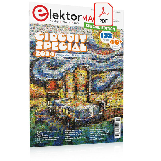
Elektor Digital Elektor Circuit Special 2024 PDF (EN)
Elektor GREEN and GOLD members can download their digital edition here. Not a member yet? Click here. Digital Load for High-Current TestingFrom Necessity to Innovation Vocal RemoverInstant Karaoke Circuit Audio A/B Selector With Gain ControlSwitches from Microphone to Line Inputs Better Charging for the LIR2032Be Kind to Your Coin Cells Touch Sensing Made SimpleA DIY Guide for Any Microcontroller Universal Infrared Remote SwitchA New Life for Old Remotes Microcontroller-Powered Moo BoxMaking Playful Sounds With a Microcontroller USB Battery Interface Powering Low-Draw Devices With Power BanksA “Stay Alive” Solution Small Class-A Audio Amplifier With Current OutputDrive Speakers with Current Instead of Voltage Pseudo-Balanced ModuleHigh CMRR with Unbalanced Audio Links Ni-MH Cells Automatic ChargerRefill All Your Battery Packs in One Go! Thyristor-Based Power Supply Protection Fingerprint Sensor SwitchA Useful Proof-of-Identity Device DC-DC 3-A Power ConverterUpgrade Your Fixed-Voltage Sources Remote Water Heater MonitorVoltage and Current Detection for AC Lines Attenuators for Audio Signals (1)Adjustable Via Jumpers Pimp My Car Battery Charger (Part 1)Don’t Throw It Away, Mod It! A Board for the Blue OnePCB for Alps Motorized Potentiometer with Feedback 50-Hz Reference from 60-Hz Mains VoltageHow to Use 50-Hz Electronics in 60-Hz Environments Digital IsolatorsRealizing Galvanic Isolation Easily Compact 12-W Hi-Fi Mono AmplifierSmall But Powerful LM386 Ramp Generator Three-Phase GeneratorWith Raspberry Pi Pico Door Opener for the Musically Talented Elektor Classic: Surf SynthesizerOcean Watersports Background Sound Generator (OWBSG) Pimp my Car Battery Charger (Part 2)Don’t Throw It Away, Mod It! Lamp Current MonitorWith a Raspberry Pi Pico Infrared Telegraphy Fnirsi SWM-10Repair Battery Packs With This Portable Intelligent Spot Welding Machine Stereo Audio Codec for the ESP32 and Co.No Need to Be Afraid of Audio Measurement Technology Tin Soldering TechniquesMake Them Well Right Away! Attenuators for Audio Signals (2)Switching Via Relays USB-C PowerDrawing Power from USB-C Power Adapters Three Circuits with Two and Three Counter ICs4017 ICs Working Together Active Components – The Diode A Timer For Ultra-Long DelaysSet It, and Forget It! Jack In and Jack OutA Useful Insert Option for Audio Circuits Power an ESP32 from a Single Li-ion Cell Hexadoku
€ 7,50
-

Elektor Digital Practical Electronics Crash Course (E-book)
Learning circuit design the fun way Welcome to the world of electronics! Getting started in electronics is not as difficult as you may think. Using this book, you will explore and learn the most important electrical and electronics engineering concepts in a fun way by doing various experiments and by simulating circuits. It will teach you electronics practically without getting into complex technical jargon and long calculations. As a result, you will be creating your own projects soon. No prior knowledge of electronics is required, only some basic algebra is used in a few simple calculations. Many tested and working projects and simulations are presented to familiarise yourself with the construction of electronic circuits. Circuit simulation is introduced at an early stage to enable you to experiment with circuits easily without breaking anything. You will learn: The concepts of voltage, current, and power AC and DC Basic lamp circuits with switches Passive components: resistors, capacitors & inductors RC & RCL circuits Electromagnetism Loudspeakers, relays, buzzers, and transformers Active components: diodes & LEDs, bipolar transistors & MOSFETs Transistor-based switching circuits Optocoupler circuits Astable & monostable multivibrators Using the 555 timer IC The operational amplifier Digital logic Advanced examples: amplifiers, oscillators, filters, and sensors Test and measurement tools Microcontrollers: Arduino UNO, ESP32, Raspberry Pi Pico, and Raspberry Pi Reading datasheets and best practices for selecting components EMC & EMI and norms & regulations
€ 32,95
Members: € 29,66
-

Elektor Digital Elektor March/April 2021 (PDF) EN
The Vision and Engineering Behind SparkFun Getting Started with MicroMod Leveling Up Your SparkFun JetBotHow I Expanded the Functionality of My JetBot, Powered by the NVIDIA Jetson Nano Programming an FPGA How to Build a DIY GNSS Reference Station The ClockClock Project Under the Hood: SparkFun Inventor's Kit SparkFun’s Glenn Samala on Product Development and New Ventures Creating Custom Circuit Boards with SparkFun À La Carte Designing with the SparkFun Artemis Getting Started with the Qwiic Ecosystem for Rapid Prototyping Poster - Qwiic Under the Hood: The GreatScott! / Elektor DIY LiPo Supercharger Kit Memorable Electronics from SparkFun Past Perfect Parking with LiDAR Buried Pad PCB Fixing Design to Sale: the SparkFun RTK Surveyor Hello World from the Raspberry Pi Pico and RP2040A Look at Raspberry Pi’s First Microcontroller and Microcontroller Chip DIY Quadrupedal Robots Poster - Micromod RISC-V IoT Development in AWS Using FreeRTOS Libraries Yep, Electronics = Fun!A Conversation Among Electronics Enthusiasts Sparkfun Product Catalog HexadokuThe Original Elektorized Sudoku
€ 7,50
-
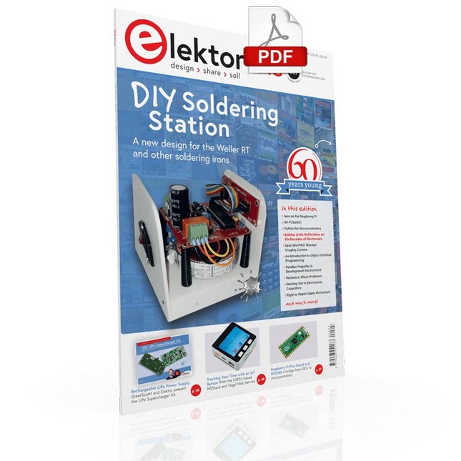
Elektor Digital Elektor May/June 2021 (PDF) EN
DIY LiPo Supercharger KitFrom Handcrafted to Mass Market Elektor @ 60Reflections on Six Decades of Electronics Siglent Bench Multimeter SDM3045X DC Current-Sense ClampHall Sensor + Ferrite Core + Arduino Soldering Station 2021Easy to build! Hands On the Parallax Propeller 2Part 2: The Development Environment and Code Wi-Fi for LoRa SwitchIntegrated in Home Assistant with ESPHome Do Not Fear the Cellular Module! Tracking Time with ESP32 and TogglWorking with the M5Stack Get to Know the Raspberry Pi Pico Board and RP2040 MicroPython for MicrocontrollersSmall-Format Screens 12-to-200-V DC/DC Converter for Valve Amplifiers Heat SeekerThe Seek Shot Pro Thermal Imaging Camera Object-Oriented Programming: A Short Primer Using C++ HomeLab ToursHome Lab and an Analogue Synthesiser by Kurt Diedrich Java on the Raspberry PiPart 1: GPIOs DIP SwitchesPeculiar Parts, the series Project 2.0Corrections, Updates and Readers’ Letters Whose Product Is It Anyway?Right to Repair Gains Momentum From Life's ExperienceThe Great Book of Blunders Micro-ProfessorLearning Assembly Language on a Z80 Starting out in ElectronicsEasier Than Imagined! Even When It Is About Capacitors HexadokuThe Original Elektorized Sudoku
€ 7,50
-

SunFounder SunFounder Kepler Kit (Ultimate Starter Kit for Raspberry Pi Pico W)
Your gateway to IoT and microcontroller programming With 450+ components and 117 online projects, this comprehensive kit ignites your creativity. The tutorials by Paul McWhorter make learning enjoyable for beginners and advanced users. This kit supports MicroPython, C/C++, and Piper Make, offering diverse programming options. Explore sensors, actuators, LEDs, and LCDs for endless project possibilities. From home automation to robotics, this kit empowers your tech journey. Features IoT Starter Kit for Beginners: This kit offers a rich IoT learning experience for beginners. With 450+ components, 117 projects, and expert-led video lessons, this kit makes learning microcontroller programming and IoT engaging and accessible. Expert-Guided Video Lessons: The kit includes 27 video tutorials by the renowned educator, Paul McWhorter. His engaging style simplifies complex concepts, ensuring an effective learning experience in microcontroller programming. Wide Range of Hardware: The kit includes a diverse array of components like sensors, actuators, LEDs, LCDs, and more, enabling you to experiment and create a variety of projects with the Raspberry Pi Pico W. Supports Multiple Languages: The kit offers versatility with support for three programming languages - MicroPython, C/C++, and Piper Make, providing a diverse programming learning experience. Dedicated Support: Benefit from our ongoing assistance, including a community forum and timely technical help for a seamless learning experience. Included Raspberry Pi Pico W Breadboard Jumper Wires Resistor Transistor Capacitor Diode Li-po Charger Module 74HC595 TA6586 – Motor Driver Chip LED RGB LED LED Bar Graph 7-segment Display 4-Digit 7-Segment Display LED Dot Matrix I²C LCD1602 WS2812 RGB 8 LEDs Strip Buzzer DC Motor Servo DC Water Pump Relay Button Micro Switch Slide Switch Potentiometer Infrared Receiver Joystick Module 4x4 Keypad MPR121 Module MFRC522 Module Photoresistor Thermistor Tilt Switch Reed Switch PIR Motion Sensor Module Water Level Sensor Module Ultrasonic Module DHT11 Humiture Sensor MPU6050 Module Documentation Online Tutorials in 3 languages (EN, DE and JP)
-

Elektor Bundles Mikrocontroller-Praxiskurs für Arduino-Einsteiger (Bundle)
Mit dem Elektor Arduino Nano Trainingsboard (MCCAB) eigene Projekte realisieren Der Mikrocontroller ist das wohl faszinierendste Teilgebiet der Elektronik, denn aufgrund der Vielzahl von Funktionen, die er auf seinem Chip vereinigt, ist er für den Entwickler ein universelles Multi-Tool zur Realisierung seiner Projekte. Praktisch jedes Gerät des täglichen Gebrauchs wird heute von einem Mikrocontroller gesteuert. Für einen elektronischen Laien blieb es aufgrund der Komplexität bisher allerdings ein Wunschtraum, eigene Ideen mit einem Mikrocontroller zu realisieren. Das Arduino-Konzept hat den Einsatz von Mikrocontrollern weitgehend vereinfacht, sodass jetzt auch Laien eigene Elektronik-Ideen mit einem Mikrocontroller verwirklichen können. Buch & Hardware im Bundle: 'Learning by Doing' Dieses im Bundle mitgelieferte Buch (im großen A4-Format) zeigt, wie man auch ohne große Erfahrung in Elektronik und Programmiersprachen eigene Projekte mit einem Mikrocontroller realisieren kann. Es ist ein Mikrocontroller-Praxiskurs für Einsteiger, denn nach einem Überblick über die Interna des Mikrocontrollers und einer Einführung in die Programmiersprache C liegt der Schwerpunkt des Kurses auf den praktischen Übungen. Der Leser eignet sich die erforderlichen Kenntnisse durch 'Learning by Doing' an: in dem umfangreichen Praxisteil mit 12 Projekten und 46 Übungen wird das im vorderen Teil des Buches Gelernte mit vielen Beispielen unterlegt. Die Übungen sind dabei so aufgebaut, dass der Bearbeiter eine Aufgabenstellung erhält, die er mit seinem im Theorieteil des Buches aufgebauten Wissen löst. Für jede Übung gibt es anschließend eine ausführlich erklärte und kommentierte Musterlösung, die dem Bearbeiter bei Problemen weiterhilft und die er mit seiner eigenen Lösung vergleichen kann. Arduino IDE In der Arduino IDE, einer Software-Entwicklungsumgebung, die kostenlos auf den eigenen PC heruntergeladen werden kann und die das gesamte Softwarepaket enthält, das für ein eigenes Mikrocontroller-Projekt benötigt wird, schreibt der Bearbeiter mit dem Editor der IDE seine Programme („Apps“) in der Programmiersprache C. Der in die Arduino IDE integrierte Compiler übersetzt sie in die Bits und Bytes, die der Mikrocontroller versteht und die dann über ein USB-Kabel in den Speicher des Mikrocontrollers auf dem Elektor Arduino Nano Trainingsboard (MCCAB) geladen werden. Externe Sensoren, Motoren oder Baugruppen abfragen oder steuern Das Elektor Arduino Nano Trainingsboard (MCCAB) enthält neben einem Mikrocontrollermodul Arduino Nano alle für die Übungen benötigten Bauteile wie Leuchtdioden, Schalter, Taster, akustische Signalgeber usw. Auch externe Sensoren, Motoren oder Baugruppen können mit diesem Mikrocontroller-Übungssystem abgefragt oder gesteuert werden. Technische Daten (Arduino Nano Trainingsboard MCCAB) Stromversorgung Über die USB-Verbindung des zur Erstellung der Programme sowieso angeschlossenen PCs oder ein externes Netzteil (nicht im Lieferumfang enthalten) Betriebsspannung +5 Vcc Eingangsspannung Alle Eingänge 0 V bis +5 V VX1 und VX2 +8 V bis +12 V (nur bei Verwendung eines externen Netzteils) Mikrocontrollermodul Arduino Nano Hardwareperipherie LCD 2x16 Zeichen Potenziometer P1 & P2 JP3: Auswahl der Betriebsspannung von P1 & P2 Verteiler SV4: Verteiler für die BetriebsspannungenSV5, SV6: Verteiler für die Ein-/Ausgänge des Mikrocontrollers Schalter und Taster RESET-Taster auf dem Arduino Nano-Modul6x Tastschalter K1 … K66x Schiebeschalter S1 … S6JP2: Verbindung der Schalter mit den Eingängen des Mikrocontrollers Summer Piezo-Summer Buzzer1 mit Steckbrücke auf JP6 Leuchtanzeigen LED L auf dem Arduino Nano-Modul, verbunden mit GPIO D1311x LED: Zustandsanzeige für die Ein-/AusgängeJP6: Verbindung der LEDs LD10 … LD20 mit den GPIOs D2 … D12 Serielle SchnittstellenSPI & I²C JP4: Auswahl des Signals an Pin X der SPI-Steckerleiste SV12SV9 bis SV12: SPI-Interface (3,3 V/5 V) bzw. I²C-Interface Schaltausgang für externe Geräte SV1, SV7: Schaltausgang (maximal +24 V/160 mA, extern zugeführt)SV2: 2x13 Pins zum Anschluss externer Module 3x3 LED-Matrix (9 rote LEDs) SV3: Spalten der 3x3 LED-Matrix (Ausgänge D6 … D8)JP1: Verbindung der Reihen mit den GPIOs D3 … D5 Software Library MCCABLib Steuerung der Hardware-Komponenten (Schalter, Taster, Leuchtdioden, 3x3 LED-Matrix, Summer) auf dem MCCAB Trainingsboard Betriebstemperatur bis +40 °C Abmessungen 100 x 100 x 20 mm Technische Daten (Arduino Nano) Mikrocontroller ATmega328P Architektur AVR Betriebsspannung 5 V Flashspeicher 32 KB, davon 2 KB vom Bootloader belegt SRAM 2 KB Taktfrequenz 16 MHz Analoge IN-Pins 8 EEPROM 1 KB DC-Strom pro I/O-Pin 40 mA an einem I/O-Pin, insgesamt maximal 200 mA an allen Pins gemeinsam Eingangsspannung 7-12 V Digitale I/O-Pins 22 (6 davon sind PWM-fähig) PWM-Ausgänge 6 Stromverbrauch 19 mA Abmessungen 18 x 45 mm Gewicht 7 g Lieferumfang Elektor Arduino Nano MCCAB Trainingsboard Arduino Nano Buch: Mikrocontroller-Praxiskurs für Arduino-Einsteiger
-

NXP Semiconductors NXP FRDM-MCXN947 Development Board
The FRDM-MCXN947 is a compact and versatile development board designed for rapid prototyping with MCX N94 and N54 microcontrollers. It features industry-standard headers for easy access to the MCU's I/Os, integrated open-standard serial interfaces, external flash memory, and an onboard MCU-Link debugger. Specifications Microcontroller MCX-N947 Dual Arm Cortex-M33 cores @ 150 MHz each with optimized performance efficiency, up to 2 MB dual-bank flash with optional full ECC RAM, External flash Accelerators: Neural Processing Unit, PowerQuad, Smart DMA, etc. Memory Expansion *DNP Micro SD card socket Connectivity Ethernet Phy and connector HS USB-C connectors SPI/I²C/UART connector (PMOD/mikroBUS, DNP) WiFi connector (PMOD/mikroBUS, DNP) CAN-FD transceiver Debug On-board MCU-Link debugger with CMSIS-DAP JTAG/SWD connector Sensor P3T1755 I³C/I²C Temp Sensor, Touch Pad Expansion Options Arduino Header (with FRDM expansion rows) FRDM Header FlexIO/LCD Header SmartDMA/Camera Header Pmod *DNP mikroBUS User Interface RGB user LED, plus Reset, ISP, Wakeup buttons Included 1x FRDM-MCXN947 Development Board 1x USB-C Cable 1x Quick Start Guide Downloads Datasheet Block diagram
-
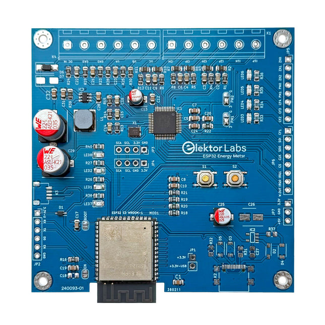
Elektor Labs Elektor ESP32 Energy Meter
The Elektor ESP32 Energy Meter is a device designed for real-time energy monitoring and smart home integration. Powered by the ESP32-S3 microcontroller, it offers robust performance with modular and scalable features. The device uses a 110/230 VAC to 12 VAC step-down transformer for voltage sampling, ensuring galvanic isolation and safety. Its compact PCB layout includes screw-type terminal blocks for secure connections, a Qwiic connector for additional sensors, and a programming header for direct ESP32-S3 configuration. The energy meter is compatible with single-phase and three-phase systems, making it adaptable for various applications. The energy meter is simple to set up and integrates with Home Assistant, offering real-time monitoring, historical analytics, and automation capabilities. It provides accurate measurements of voltage, current, and power, making it a valuable tool for energy management in homes and businesses. Features Comprehensive Energy Monitoring: Get detailed insights into your energy usage for smarter management and cost savings. Customizable Software: Tailor functionality to your needs by programming and integrating custom sensors. Smart Home Ready: Compatible with ESPHome, Home Assistant, and MQTT for full Smart Home integration. Safe & Flexible Design: Operates with a 110/230 VAC to 12 VAC step-down transformer and features a pre-assembled SMD board. Quick Start: Includes one Current Transformer (CT) sensor and access to free setup resources. Specifications Microcontroller ESP32-S3-WROOM-1-N8R2 Energy Metering IC ATM90E32AS Status Indicators 4x LEDs for power consumption indication2x Programmable LEDs for custom status notifications User Input 2x Push buttons for user control Display Output I²C OLED display for real-time power consumption visualization Input Voltage 12~16 VAC (via a step-down transformer 110/230 VAC to 12 VAC) Clamp Current Sensor YHDC SCT013-000 (100 A/50 mA) included Smart Home Integration ESPHome, Home Assistant, and MQTT for seamless connectivity Connectivity Header for programming, Qwiic for sensor expansion Applications Supports single-phase and three-phase energy monitoring systems Dimensions 79.5 x 79.5 mm Included 1x Partly assembled board (SMDs are pre-mounted) 2x Screw terminal block connectors (not mounted) 1x YHDC SCT013-000 current transformer Required Power transformer not included Downloads Datasheet (ESP32-S3-WROOM-1) Datasheet (ATM90E32AS) Datasheet (SCT013-000) Frequently Asked Questions (FAQ) From Prototype to Finished Product What started as an innovative project to create a reliable and user-friendly energy meter using the ESP32-S3 microcontroller has evolved into a robust product. Initially developed as an open-source project, the ESP32 Energy Meter aimed to provide precise energy monitoring, smart home integration and more. Through meticulous hardware and firmware development, the energy meter now stands as a compact, versatile solution for energy management.
-
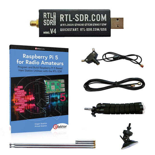
Elektor Bundles Raspberry Pi 5 RTL-SDR V4 (Bundle)
Program and build Raspberry Pi based ham station utilities, tools, and instruments The improved RTL-SDR V4 allows you to receive radio signals between 500 kHz and 1.75 GHz from stations utilizing different bands including MW/SW/LW broadcast, ham radio, utility, air traffic control, PMR, SRD, ISM, CB, weather satellite, and radio astronomy. The book Raspberry Pi 5 for Radio Amateurs gives extensive coverage of deploying the RTL-SDR kit through the use of a Raspberry Pi 5. This bundle contains: RTL-SDR V4 (incl. Dipole Antenna Kit) (normal price: €75) Raspberry Pi 5 for Radio Amateurs (normal price: €40) RTL-SDR V4 (Software Defined Radio) with Dipole Antenna Kit RTL-SDR is an affordable dongle that can be used as a computer-based radio scanner for receiving live radio signals between 500 kHz and 1.75 GHz in your area. The RTL-SDR V4 offers several improvements over generic brands including use of the R828D tuner chip, triplexed input filter, notch filter, improved component tolerances, a 1 PPM temperature compensated oscillator (TCXO), SMA F connector, aluminium case with passive cooling, bias tee circuit, improved power supply, and a built in HF upconverter. RTL-SDR V4 comes with the portable dipole antenna kit. It is great for beginners as it allows for terrestrial and satellite reception and easy to mount outdoors and designed for portable and temporary outside usage. Features Improved HF reception: V4 now uses a built-in upconverter instead of using a direct sampling circuit. This means no more Nyquist folding of signals around 14.4 MHz, improved sensitivity, and adjustable gain on HF. Like the V3, the lower tuning range remains at 500 kHz and very strong reception may still require front end attenuation/filtering. Improved filtering: The V4 makes use of the R828D tuner chip, which has three inputs. The SMA input has been triplexed input into 3 bands: HF, VHF and UHF. This provides some isolation between the 3 bands, meaning out of band interference from strong broadcast stations is less likely to cause desensitization or imaging. Improved filtering x2: In addition to the triplexing, the open drain pin on the R828D can be also used, which allows to add simple notch filters for common interference bands such as broadcast AM, broadcast FM and the DAB bands. These only attenuate by a few dB, but may still help. Improved phase noise on strong signals: Due to an improved power supply design, phase noise from power supply noise has been significantly reduced. Less heat: Another advantage of the improved power supply is low power consumption and less heat generation compared to the V3. Included 1x RTL-SDR V4 dongle (R828D RTL2832U 1PPM TCXO SMA) 2x 23 cm to 1 m telescopic antenna 2x 5 cm to 13 cm telescopic antenna 1x Dipole antenna base with 60 cm RG174 1x 3 m RG174 extension cable 1x Flexible tripod mount 1x Suction cup mount Downloads Datasheet User Guide Quick Start Guide SDR# User Guide Dipole Antenna Guide Book: Raspberry Pi 5 for Radio Amateurs The RTL-SDR devices (V3 and V4) have gained popularity among radio amateurs because of their very low cost and rich features. A basic system may consist of a USB based RTL-SDR device (dongle) with a suitable antenna, a Raspberry Pi 5 computer, a USB based external audio input-output adapter, and software installed on the Raspberry Pi 5 computer. With such a modest setup, it is possible to receive signals from around 24 MHz to over 1.7 GHz. This book is aimed at amateur radio enthusiasts and electronic engineering students, as well as at anyone interested in learning to use the Raspberry Pi 5 to build electronic projects. The book is suitable for both beginners through experienced readers. Some knowledge of the Python programming language is required to understand and eventually modify the projects given in the book. A block diagram, a circuit diagram, and a complete Python program listing is given for each project, alongside a comprehensive description. The following popular RTL-SDR programs are discussed in detail, aided by step-by-step installation guides for practical use on a Raspberry Pi 5: SimpleFM GQRX SDR++ CubicSDR RTL-SDR Server Dump1090 FLDIGI Quick RTL_433 aldo xcwcp GPredict TWCLOCK CQRLOG klog Morse2Ascii PyQSO Welle.io Ham Clock CHIRP xastir qsstv flrig XyGrib FreeDV Qtel (EchoLink) XDX (DX-Cluster) WSJT-X The application of the Python programming language on the latest Raspberry Pi 5 platform precludes the use of the programs in the book from working on older versions of Raspberry Pi computers.
-
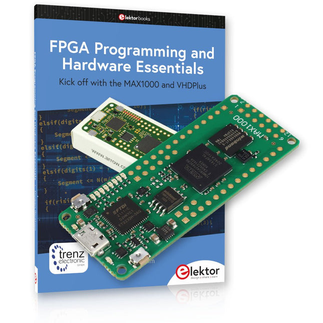
Elektor Bundles MAX1000 FPGA Programming Bundle
Kick off to FPGA Programming with the MAX1000 Board and VHDPlus Ready to master FPGA programming? With this bundle, you'll dive into the world of Field-Programmable Gate Arrays (FPGAs) – a configurable integrated circuit that can be programmed after manufacturing. Bring your ideas to life, from simple projects to complete microcontroller systems! The MAX1000 is a compact and powerful FPGA development board packed with features like memory, user LEDs, push-buttons, and flexible I/O ports. It’s the ideal starting point for anyone wanting to learn about FPGAs and Hardware Description Languages (HDLs). With the enclosed book "FPGA Programming and Hardware Essentials" you'll get hands-on with the VHDPlus programming language – a simpler version of VHDL. You'll work on practical projects using the MAX1000, helping you gain the skills and confidence to unleash your creativity. Projects in the Book Arduino-driven BCD to 7-Segment Display Decoder Use an Arduino Uno R4 to supply BCD data to the decoder, counting from 0 to 9 with a one-second delay Multiplexed 4-Digit Event Counter Create an event counter that displays the total count on a 4-digit display, incrementing with each button press PWM Waveform with Fixed Duty Cycle Generate a PWM waveform at 1 kHz with a fixed duty cycle of 50% Ultrasonic Distance Measurement Measure distances using an ultrasonic sensor, displaying the results on a 4-digit 7-segment LED Electronic Lock Build a simple electronic lock using combinational logic gates with push buttons and an LED output Temperature Sensor Monitor ambient temperature with a TMP36 sensor and display the readings on a 7-segment LED MAX1000 FPGA Development Board The MAX1000 is a customizable IoT/Maker Board ready for evaluation, development and/or use in a product. It is built around the Intel MAX10 FPGA, which is the industry’s first single chip, non-volatile programmable logic device (PLDs) to integrate the optimal set of system components. Users can now leverage the power of tremendous re-configurability paired with a high-performance, low-power FPGA system. Providing internally stored dual images with self-configuration, comprehensive design protection features, integrated ADCs and hardware to implement the Nios II 32-bit microcontroller IP, MAX10 devices are ideal solution for system management, protocol bridging, communication control planes, industrial, automotive and consumer applications. The MAX1000 is equipped with an Arrow USB Programmer2, SDRAM, flash memory, accelerometer sensor and PMOD/Arduino MKR connectors making it a fully featured plug and play solution without any additional costs. Specifications MAX 10 8 kLE - Flash Dual inside - ADC 8x 12 Bit - Temperature Range 0~85°C - Supply USB/pins SDRAM 8 MB 3-axis MEMS LIS3DH USB Programmer on board MEMS Oscillator 12 MHz Switch/LED 2x / 8x Contents of the Bundle Book: FPGA Programming and Hardware Essentials (normal price: €40) MAX1000 FPGA Development Board (normal price: €45) Downloads Software


