
Search results for "accurate OR universal OR measurement OR interface"
-
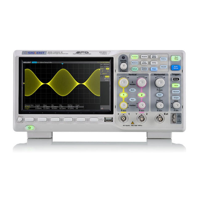
Siglent Siglent SDS1202X-E 2-ch Oscilloscope (200 MHz)
SIGLENT’s SDS1000X-E Series Super Phosphor Oscilloscope is available in one bandwidth, 200 MHz. It has a maximum sample rate of 1 GSa/s and a standard record length of 1 Mpts. For ease-of-use, the most commonly used functions can be accessed with its user-friendly front panel design. The SDS1000X-E series employs a new generation of SPO (Super Phosphor Oscilloscope) technology that provides excellent signal fidelity and performance. The system noise is also lower than similar products in the industry. It comes with a minimum vertical input range of 500 uV/div, an innovative digital trigger system with high sensitivity and low jitter, and a waveform capture rate of 400,000 frames/ sec (sequence mode). The SDS1000X-E also employs a 256-level intensity grading display function and a color temperature display mode not found in other models in this class. Siglent’s latest oscilloscopes offering supportsmultiple powerful triggering modes including serial bus triggering. Decoding is standard configuration including IIC,SPI,UART,CAN,LIN. History waveform recording and sequential triggering enable extended waveform recording and analysis. Another powerful addition is the new 1 million points FFT math function that gives the SDS1000X-E very high frequency resolution when observing signal spectra. The new design also includes a hardware co-processor that delivers measurements quickly and accurately. The features and performance of Siglent’s new SDS1000X-E cannot be matched anywhere else in this price class. Specifications Bandwidth 200 MHz Channels 2CH+1EXT Real time sampling rate 1 GSa/s Memory depth 7 Mpts/CH (Dual-Channel); 14 Mpts/CH (Single-Channel) Waveform Capture Rate (Max.) 100,000 wfm/s (normal mode); 400,000 wfm/s (sequence mode) Serial Trigger (Standard) I²C, SPI, UART/RS232, CAN, LIN Decode Type (Standard) I²C, SPI, UART/RS232, CAN, LIN Trigger Type Edge, Slope, Pulse Width, Window, Runt, Interval, Dropout, Pattern, Video Probe (Std) 2 pcs passive probe PP215 Display 7 inch TFT-LCD (800x480) Weight Without package 2.5 kg; with package 3.5 kg Downloads Datasheet Manual Programming Guide
€ 401,99
-
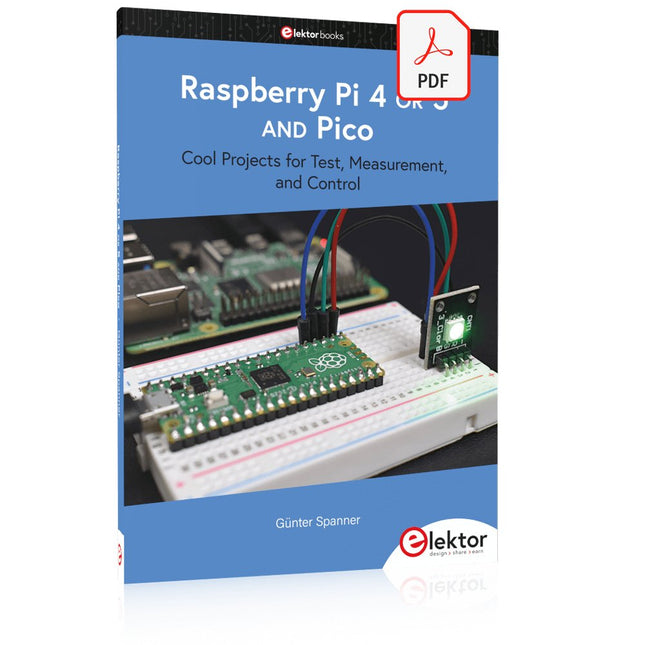
Elektor Digital Raspberry Pi 4 OR 5 AND Pico (E-book)
Cool Projects for Test, Measurement, and Control The Raspberry Pi has dominated the maker scene for many years. Freely accessible I/O pins have made it one of the most popular processor boards of all time. However, the classic Raspberry Pi has no analog inputs. Direct measurement of analog values is therefore not possible. Consequently, photodiodes, NTCs, Hall sensors, etc. cannot be read directly. In addition, the pins are connected directly to the exposed contacts, i.e. without a driver or protection circuit. This can quickly destroy the central controller and thus the entire Raspberry Pi. These problems can be elegantly solved with the Pico. As a front-end, it can easily handle a wide range of measurement tasks. In addition, the Pico is much cheaper than a classic Raspberry Pi 4 or 5. If a faulty circuit leads to the destruction of the Pico, this is relatively easy to handle. This makes the combination of a classic Raspberry Pi 4 or 5 and the Pico an ideal pair. The book introduces the broad and highly topical field of modern controller technology using the combined force of a Raspberry Pi 4 or 5 and a Raspberry Pi Pico. In addition to a detailed introduction to the operation and functionality of the controller boards themselves, the book also focuses on data acquisition and processing with digital processors. Especially the combination of both systems offers a wide range of interesting possibilities. Some practical projects from the contents: USB between Raspberry Pi 4 or 5 and Pico I²C Communication and Pico as an I²C device Voltmeter and Computer Thermometer Pico W as a Web Server and WLAN Scanner Frequency Meters and Generators OLED Displays on Raspberry Pi 4 or 5 and Pico Energy Saving Monitor Which Astronauts are in Orbit? Mini Monitor for Current Bitcoin Exchange Rate
€ 32,95
Members: € 29,66
-
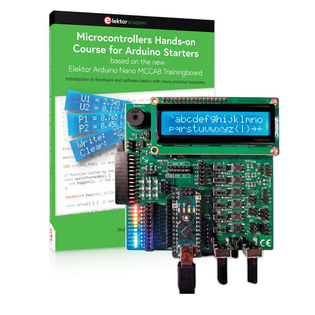
Elektor Bundles Microcontrollers Hands-on Course for Arduino Starters (Bundle)
Realize your own projects with the Elektor Arduino Nano MCCAB Training Board The microcontroller is probably the most fascinating subfield of electronics. Due to the multitude of functions, it combines on its chip, it is a universal multi-tool for developers to realize their projects. Practically every device of daily use today is controlled by a microcontroller. However, for an electronic layman, realizing his own ideas with a microcontroller has so far remained a pipe dream due to its complexity. The Arduino concept has largely simplified the use of microcontrollers, so that now even laymen can realize their own electronics ideas with a microcontroller. Book & Hardware in the Bundle: 'Learning by Doing' This book, which is included in the bundle, shows how you can realize your own projects with a microcontroller even without much experience in electronics and programming languages. It is a microcontrollers hands-on course for starters, because after an overview of the internals of the microcontroller and an introduction to the programming language C, the focus of the course is on the practical exercises. The reader acquires the necessary knowledge by 'learning by doing': in the extensive practical section with 12 projects and 46 exercises, what is learned in the front part of the book is underpinned with many examples. The exercises are structured in such a way that the user is given a task to solve using the knowledge built up in the theoretical part of the book. Each exercise is followed by a sample solution that is explained and commented on in detail, which helps the user to solve problems and compare it with his own solution. Arduino IDE The Arduino IDE is a software development environment that can be downloaded for free to your own PC and that contains the entire software package needed for your own microcontroller projects. You write your programs ('apps') with the IDE’s editor in the C programming language. You translate them into the bits and bytes that the microcontroller understands using the Arduino IDE's built-in compiler, and then load them into the microcontroller's memory on the Elektor Arduino MCCAB Nano Training Board via a USB cable. Query or control external sensors, motors or assemblies In addition to an Arduino Nano microcontroller module, the Elektor Arduino Nano MCCAB Training Board contains all the components required for the exercises, such as light-emitting diodes, switches, pushbuttons, acoustic signal transmitters, etc. External sensors, motors or assemblies can also be queried or controlled with this microcontroller training system. Specifications (Arduino Nano MCCAB Training Board) Power Supply Via the USB connection of the connected PC or an external power supply unit (not included) Operating Voltage +5 Vcc Input Voltage All inputs 0 V to +5 V VX1 and VX2 +8 V to +12 V (only when using an external power supply) Hardware periphery LCD 2x16 characters Potentiometer P1 & P2 JP3: selection of operating voltage of P1 & P2 Distributor SV4: Distributor for the operating voltagesSV5, SV6: Distributor for the inputs/outputs of the microcontroller Switches and buttons RESET button on the Arduino Nano module 6x pushbutton switches K1 ... K6 6x slide switches S1 ... S6 JP2: Connection of the switches with the inputs of the microcontroller Buzzer Piezo buzzer Buzzer1 with jumper on JP6 Indicator lights 11 x LED: Status indicator for the inputs/outputs LED L on the Arduino Nano module, connected to GPIO D13 JP6: Connection of LEDs LD10 ... LD20 with GPIOs D2 ... D12 Serial interfacesSPI & I²C JP4: Selection of the signal at pin X of the SPI connector SV12 SV9 to SV12: SPI interface (3.3 V/5 V) or I²C interface Switching output for external devices SV1, SV7: Switching output (maximum +24 V/160 mA, externally supplied) SV2: 2x13 pins for connection of external modules 3x3 LED matrix(9 red LEDs) SV3: Columns of the 3x3 LED matrix (outputs D6 ... D8) JP1: Connection of the rows with the GPIOs D3 ... D5 Software Library MCCABLib Control of hardware components (switches, buttons, LEDs, 3x3 LED matrix, buzzer) on the MCCAB Training Board Operating Temperature Up to +40 °C Dimensions 100 x 100 x 20 mm Specifications (Arduino Nano) Microcontroller ATmega328P Architecture AVR Operating Voltage 5 V Flash Memory 32 KB, of which 2 KB used by bootloader SRAM 2 KB Clock Speed 16 MHz Analog IN Pins 8 EEPROM 1 KB DC Current per I/O Pins 40 mA on one I/O pin, total maximum 200 mA on all pins together Input Voltage 7-12 V Digital I/O Pins 22 (6 of which are PWM) PWM Output 6 Power Consumption 19 mA Dimensions 18 x 45 mm Weight 7 g Included Elektor Arduino Nano MCCAB Training Board Arduino Nano Book: Microcontrollers Hands-on Course for Arduino Starters
€ 139,95
Members: € 125,96
-
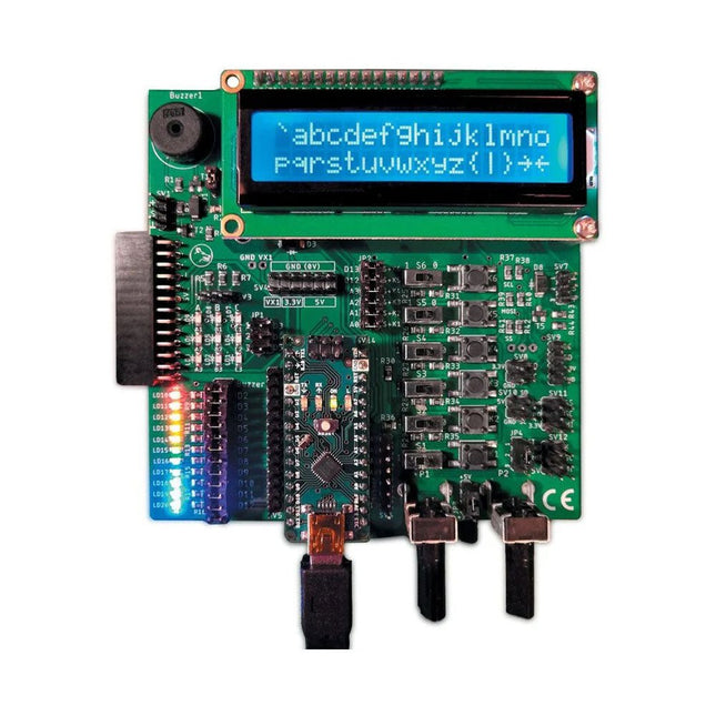
Elektor Labs Elektor Arduino Nano MCCAB Training Board
The Elektor Arduino Nano MCCAB Training Board contains all the components (incl. Arduino Nano) required for the exercises in the "Microcontrollers Hands-on Course for Arduino Starters", such as light-emitting diodes, switches, pushbuttons, acoustic signal transmitters, etc. External sensors, motors or assemblies can also be queried or controlled with this microcontroller training system. Specifications (Arduino Nano MCCAB Training Board) Power Supply Via the USB connection of the connected PC or an external power supply unit (not included) Operating Voltage +5 Vcc Input Voltage All inputs 0 V to +5 V VX1 and VX2 +8 V to +12 V (only when using an external power supply) Hardware periphery LCD 2x16 characters Potentiometer P1 & P2 JP3: selection of operating voltage of P1 & P2 Distributor SV4: Distributor for the operating voltagesSV5, SV6: Distributor for the inputs/outputs of the microcontroller Switches and buttons RESET button on the Arduino Nano module 6x pushbutton switches K1 ... K6 6x slide switches S1 ... S6 JP2: Connection of the switches with the inputs of the microcontroller Buzzer Piezo buzzer Buzzer1 with jumper on JP6 Indicator lights 11 x LED: Status indicator for the inputs/outputs LED L on the Arduino Nano module, connected to GPIO D13 JP6: Connection of LEDs LD10 ... LD20 with GPIOs D2 ... D12 Serial interfacesSPI & I²C JP4: Selection of the signal at pin X of the SPI connector SV12 SV9 to SV12: SPI interface (3.3 V/5 V) or I²C interface Switching output for external devices SV1, SV7: Switching output (maximum +24 V/160 mA, externally supplied) SV2: 2x13 pins for connection of external modules 3x3 LED matrix(9 red LEDs) SV3: Columns of the 3x3 LED matrix (outputs D6 ... D8) JP1: Connection of the rows with the GPIOs D3 ... D5 Software Library MCCABLib Control of hardware components (switches, buttons, LEDs, 3x3 LED matrix, buzzer) on the MCCAB Training Board Operating Temperature Up to +40 °C Dimensions 100 x 100 x 20 mm Specifications (Arduino Nano) Microcontroller ATmega328P Architecture AVR Operating Voltage 5 V Flash Memory 32 KB, of which 2 KB used by bootloader SRAM 2 KB Clock Speed 16 MHz Analog IN Pins 8 EEPROM 1 KB DC Current per I/O Pins 40 mA on one I/O pin, total maximum 200 mA on all pins together Input Voltage 7-12 V Digital I/O Pins 22 (6 of which are PWM) PWM Output 6 Power Consumption 19 mA Dimensions 18 x 45 mm Weight 7 g Included 1x Elektor Arduino Nano Training Board MCCAB 1x Arduino Nano
€ 69,95
Best Price
-

Elektor Classics The Elektor Power Supply Collection 2026 (USB Stick)
More than 275 Power Supply Designs for Home Construction This USB Stick contains over 275 different power supply circuits from the volumes 2001-2025 of Elektor. The article search feature allows you to search full-text content. The results are always displayed as pre-formatted PDF documents. Highlights Cuk Converter Automatic Battery Switchover Battery Voltage LED Digital Benchtop Power Supply Lithium-Ion Charger Solar Cell Charger Electronic Fuse High Voltage Regulator Power Supply for USB Devices Step-up Converter for LEDs Battery Management and much more... On the Stick you will also find a folder with additional material such as PCB layouts, Gerber files and software. Specifications Storage 16 GB Interfaces 1x USB-A1x USB-C System requirements PC with Adobe Reader 7.0 or higher Web browser
€ 49,95
Members: € 44,96
-
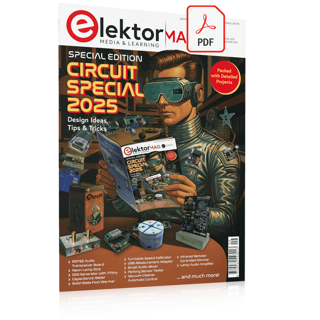
Elektor Digital Elektor Circuit Special 2025 (PDF) EN
Elektor GREEN and GOLD members can download their digital edition here. Not a member yet? Click here. USB Measurement AdapterTesting Current and Signal Quality of USB Ports 4...20 mA Current Output for Arduino UnoA Reliable, EMI-Insensitive Current Loop Interface Vacuum Cleaner Automatic ControlKeep Your Tools’ Work Area Clean DDS Generator with ATtiny Opamp-Tester V2New PCB – Now Also Suitable for SMDs 550-mW “Lamp” Audio AmplifierGet the Warm Sound of Vacuum Tubes With Ease Fuse GuardMonitoring a Fuse with a Flashing LED HQ RIAA PreamplifierGet the Most Out of Your Vinyl Records! Turntable Speed CalibratorAn Arduino-Based 100–120 Hz Strobe Light Generator Elektor Classics: video buffer/repeater Infrared Remote-Controlled DimmerControl Your Halogen or LED Floor Lamp Effortlessly and With Style How to Use switch…case on Strings in C++/Arduino IDE Magnet FinderWith a Simple Hall-Effect Sensor Raspberry Pi Smart Power ButtonA Solution for Raspberry Pi Up to Model 4 Essential Maker TipsProfessional Insights for Everyday Making Practical Projects with the 555 TimerDC Motor Control and Fast Reaction Challenges Basic AC-Load-On MonitorSave Energy with a Simple Device Power Banks in ParallelA Three-Day Continuous Power Solution VFO Up to 15 MHzAn Implementation With Raspberry Pi Pico Violin Tuner with ATtiny202 Elektor Classics: video amplifier for B/W television sets Capacitance Meter20 pF to 600 nF Quasi-Analog Clockwork Mk IITwo LED Rings for Hours and Minutes You Can Do Anything You Want(with the Arduino Ecosystem at Your Side) Neon Lamp Dice Elektor Classics: RTTY calibrator indicator Inspiring Hardware Designs for Your ESPs Elektor Classics: variable 3 A power supply RGB LEDs with Integrated Control CircuitLight with Precision: ICLEDs Set Standards Experiment: Towards a Mixed-Signal Theremin?Blending Modern Time-of-Flight Sensors With the Timeless XR2206 Analog Generator ESP32 Audio Transceiver Board (Part 1)SD Card WAV File Player Demo Infographics: Circuits and Circuit Design 2025 Small Audio MixerA Simple and Versatile Scalable Design Smart Staircase Light TimerSave More Money on the Energy Bill! Smarten Up Your ShuttersControlling Velux Hardware With an ESP32 and MQTT Solid-State Foot WarmerEnergy-Efficient Comfort Is the M5Stamp Fly Quadcopter the Next Tello? Boosting Wi-Fi Range of the ESP32-C3 SuperMiniA Simple and Effective Antenna Mod ZD-8968 Hot-Air Soldering StationA Budget-Friendly Workhorse or Just Hot Air? Parking Sensor TesterFinding Defects in the PDC System of a Car
€ 9,50
-

Elektor Digital Build Your Own Software-Defined Radio (E-book)
Practical Guide to Modular RF Design Build Your Own Software-Defined Radio combines RF circuitry with hardware programming and PC-based signal processing. The e-book presents a modular approach to building a complete SDR system using RF Bricks – from the mechanical framework and RF modules to measurement tools, PC software, and FPGA implementations. Practical explanations guide readers through real signal paths, construction steps, and measurement routines, linking hardware and software into a flexible SDR platform. Key topics include: Mechanical setup: RF Brick template, chassis, and 19-inch module carrier Bridges: USB isolator, I²C level shifter, I²C power switch, and practical examples Signal-chain design with RF Bricks: antennas, band filters, NanoVNA work, preamplifiers, PLLs, demodulators, direct-conversion chains, multiband options, and narrowband bricks RF measurement Bricks: single- and dual-tone sources, NPR methods, noise generators, notch filters, broadband amplifiers, and impedance bridges Useful accessories: ATU-100 tuner, X-Phase QRM eliminator, and firmware notes PC host software: SoapyAudio adjustments, GQRX, SDR++, and added functionality GnuRadio elements: control blocks, SSB demodulation, GUI components, messaging, and filter handling FPGA-based SDR: VHDL, toolchains, ADC/DAC blocks, oversampling, and a complete SSB/CW signal chain With its modular structure and detailed working examples, this e-book offers a practical path to building and extending modern SDR systems. Downloads Software
€ 32,95
Members: € 29,66
-

Elektor Classics The Complete Linear Audio Library (USB Stick)
Jan Didden created Linear Audio in 2010 and published 14 Volumes between 2010 and 2017. Each 200-page Volume contains on average 10 articles by expert authors in the field of audio, acoustics, and instrumentation. Whether you are interested in tube amplifiers, solid-state equipment, loudspeaker design, capacitor and resistor distortion or distortion measurement, you are certain to find helpful advice and interesting discussions. From beginner to advanced level, for the audio professional or the serious hobbyist, this ExpertCollection will advance your understanding and offer new perspectives on common issues. Bonus material included with this collection is a 5-part YouTube series on negative feedback as applied to audio by renowned author Jan Didden, and nine additional landmark audio articles and presentations. If you are seriously interested in audio, acoustics, and instrumentation, you can’t afford to miss this! The published material is indexed and fully searchable and will provide an almost limitless resource for many years to come. You can read about Linear Audio’s authors, and the Table of Contents of each Volume, at linearaudio.net.
€ 149,95
Members: € 134,96
-

Seeed Studio Seeed Studio RF Explorer WSUB1G+ Slim Spectrum Analyzer
The Seeed Studio RF Explorer WSUB1G+ is a powerful, high-performance digital spectrum analyzer covering frequencies from 50 kHz to 1 GHz. The Slim model features a robust design, a more conveniently positioned USB connector on the side, and a larger internal battery capacity. Features Internal LNA amplifier and selectable attenuator Low frequency support from 50 KHz covering LF, MF, HF, VHF and UHF up to 960 Mhz New HELP and SET buttons to improve user interface and configuration selection with 2-clicks Wide band coverage to all popular sub-1 Ghz bands, including FM, TV and DTV, ISM, RFID, GSM, etc. Ideal choice for HAM bands from 160 m to 33 cm Pocket size and light weight Solid metal case Spectrum Analyzer mode with Peak Max and Hold, Normal, Overwrite and Averaging modes High capacity internal Lithium battery for 20hs+ of continuous run, rechargeable by USB Multi-platform Windows/Linux/MacOS Open Source software and API libraries Can be extended with internal Expansion Modules for additional band and functionality Specifications Frequency band: 0.05 MHz – 960 MHz Frequency span: 0.1 MHz – 960 MHz Internal selectable LNA 25 dB gain Internal selectable Attenuator 30 dB Graphics LCD 128 x 64 pixels, great visibility outdoors Support included for Windows, Linux and MacOS X Backlight for great visibility indoor Internal Lithium Ion 1800 mA/h rechargeable battery Standard SMA 50 Ω connector Wideband 144/433 MHz dual band telescopic antenna included UHF 400-900 MHz rubber duck articulated antenna included Amplitude resolution: 0.5 dBm Dynamic range: -125 dBm to 10 dBm Absolute Max input power: +30 dBm Average noise level (typical LNA): -125 dBm Frequency stability and accuracy (typical): ±10 ppm Amplitude stability and accuracy (typical): ±2 dBm Frequency resolution: 1 kHz Resolution bandwidth (RBW): Automatic 2.6 kHz to 600 kHz Included 1x Seeed Studio RF Explorer WSUB1G+ Slim Spectrum Analyzer 1x Mini USB cable 1x Dual band 144/430 MHz Telescopic antenna 1x UHF 400-900 Mhz antenna 1x EVA case
€ 204,49
-

Elektor Publishing Experimenting with Red Pitaya STEMlab Gen 2
Practical Projects and Programs With Experimenting with Red Pitaya STEMlab Gen 2, Red Pitaya goes beyond a versatile board. It becomes a powerful laboratory instrument for precision measurement, analysis, and control. From the fundamentals of electronic project development, monitoring, control, and design to testing, this book walks you step-by-step through everything you need to know to harness the full potential of Red Pitaya hardware and software. The book presents real-time, FPGA-based projects that are developed on a PC using the Vivado environment, then transferred to the Red Pitaya for execution and testing. You will learn about enhanced performance, expanded I/O capabilities, improved FPGA features, and advanced connectivity options that open up new frontiers for precision measurement, monitoring, and control in your embedded applications. Inside the book you will discover: A deep dive into Red Pitaya architecture and hardware design Electronic experiments using Red Pitaya for measurement and monitoring Hands-on projects using the Python programming language Practical guidance for FPGA programming using Red Pitaya Red Pitaya FPGA projects using the Verilog HDL under Vivado IDE Practical design of electronic projects including measurement and testing Step-by-step examples that bridge theory and real-world implementation Whether you are designing your own electronic circuits, developing signal analysis tools, or creating real-time control or monitoring systems, this book provides you the knowledge and confidence you need to fully learn and customize the Red Pitaya platform.
€ 39,95
Members: € 35,96
-
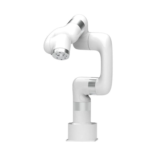
UFactory UFactory xArm 6
This multi-axis robot perfectly balances power and size. Features Payload: 5 kg Reach: 700 mm Repeatability: 0.1 mm Max Speed 1000 mm/s Applications Machine Tending Bin Picking Mobile platform Lab Automation Robotic Research Durable Collaborative robots for your automation Industrial-grade harmonic drive and servomotors guarantee 24/7 working without stop. Crafted from Carbon fiber, 15 kg weight makes it possible for easier deployment. Flexible deployment with safe feature Hand teaching, lightweight, space-saving and easy to re-deploy to multiple applications without changing your production layout. Perfectly for recurrent tasks. Collision detection is available for all of our cobots. Your safety is always the top priority. Graphical interface for beginner-friendly programming Compatible with various of operation systems, including macOS and Windows. Web-based technology compatible with all major browsers. Drag and drop to create your code in minutes. Powerful and open source SDK at your fingertips Fully functional open-source Python/C++ SDK provides more flexible programming. ROS/ROS2 packages are ready-to-go. Example codes help you to deploy the robotic arm smoothly. Specifications UFactory 850 xArm 5 xArm 6 xArm 7 Payload 5 kg 3 kg 5 kg 3.5 kg Reach 850 mm 700 mm 700 mm 700 mm Degrees of freedom 6 5 6 7 Repeatability ±0.02 mm ±0.1 mm ±0.1 mm ±0.1 mm Maximum Speed 1 m/s 1 m/s 1 m/s 1 m/s Weight (robot arm only) 20 kg 11.2 kg 12.2 kg 13.7 kg Maximum Speed 180°/s 180°/s 180°/s 180°/s Joint 1 ±360° ±360° ±360° ±360° Joint 2 -132°~132° -118°~120° -118°~120° -118°~120° Joint 3 -242°~3.5° -225°~11° -225°~11° ±360° Joint 4 ±360° -97°~180° ±360° -11°~225° Joint 5 -124°~124° ±360° -97°~180° ±360° Joint 6 ±360° ±360° -97°~180° Joint 7 ±360° Hardware xArm Robot specs Ambient Temperature Range 0-50°C Power Consumption Min 8.4 W, Typical 200 W, max 400 W Input Power Supply 24 V DC, 16.5 A Footprint Ø 126 mm Materials Aluminum, Carbon Fiber Base Connector Type M5x5 ISO Class Cleanroom 5 Robot Mounting Any End Effector Communication Protocol Modbus RTU(rs485) End Effector I/O 2x DI/2x DO/2x AI/1x RS485 Communication Mode Ethernet Included 1x xArm 6 robotic arm 1x AC control box 1x Robotic arm power cable 1x Robotic arm end effector adapter cable 1x Robotic arm signal cable 1x Control box power cable 1x Network cable 1x Mounting tool 1x Quick start guide
€ 11.259,00
Best Price
-

Elektor Digital Elektor Circuit Special 2026 (PDF) EN
Elektor GREEN and GOLD members can download their digital edition here. Not a member yet? Click here. A Current Source for Testing (Z-)DiodesChecking Z-Diodes from 1 to 54 V @ 1 to 50 mA ESD Strap TesterA Bench Tool with Pass, Borderline, and Fail Indication Power Supply Transient Response TesterA Repeatable Step-Load Generator for Bench Power Supplies Euclidean Sequencer Without a MicrocontrollerTrigger Patterns and CV Sequences with Simple CMOS Logic LED Flashing Light for Gates and More with an Audible Alert Need PCBs? The Elektor PCB Service Has You Covered. Toothbrush TimerUsing a Tiny PIC A Contactless Magnetic Combination LockWith the AS5600 Rotary Position Sensor Low-Noise Battery-Powered PreamplifierFor Dynamic Microphones The Arduino Nano TestLabMeasurement, Control, and Regulation Rhythmic Bass LightEmphasize the Rhythm of Your Music Low-Cut FilterNo Risk of Audio Feedback on Your System Precise 1 Hz Square Wave Generator for BreadboardsA Reliable CMOS-Based Clock Source 555 Upside DownDuty Cycles Down to Zero From Halfgeleidergids to Circuit Specials65 Years of Electronics Innovation Electrical IsolationCAN Interface with Digital Isolator and Power Module SpongillatorA Sponge-Based Oscillator True Random Number GeneratorWith Integrated Chi-Square Test 3D Viewer for HTML pagesSimple, and Almost Without Code Programming with TLScriptA Scripting Language for Measurement, Testing, and Control Circuit Design: Tips from Experts FeedbackWhat Is It and Why Is It Important? One Board, Endless Ideas: Arduino UNO QFrom Retro Gaming to Real-Time Environmental Monitoring How to Fix a Donut Antenna Standby KillerA Real On/Off Switch for Your TV Battery TestingMeasuring Batteries with the Arduino Nano Power Supply for Audio Power AmplifiersA Good Power Supply Without Mains Hum Prototyping Boards for RFFast Setups with DIY Prototyping Boards T3 Surge ProtectionA Type 3 Spike Suppressor for Your Sensitive Equipment IoT Room Thermostat BoardWith ESP32-C3/S3-Based Xiao MCU module From Rigid to SmartFlexible and Printed Electronics — Between Vision and Industrial Reality
€ 9,50


