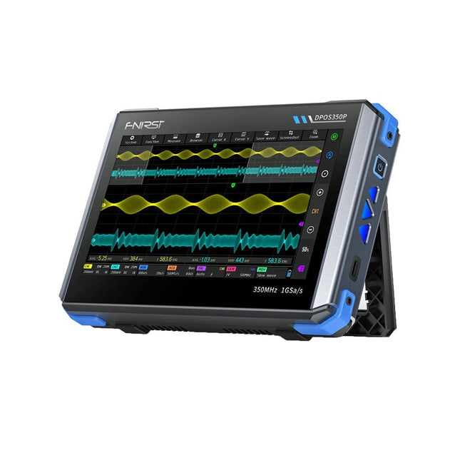
2 Channels • 350 MHz • 1 GSa/s • 50,000 wfm/s • 7 inch Touchscreen
The FNIRSI DPOS350P is a sleek 4-in-1 powerhouse in tablet form! This compact and portable device packs serious functionality: it combines a 2-channel oscilloscope (350 MHz), a signal generator (50 MHz), a frequency response analyzer (50 MHz), and a spectrum analyzer (200 kHz–350 MHz) – all in one unit.
Whether you're in R&D, troubleshooting, or field testing, the DPOS350P delivers the tools you need to measure, generate, analyze, and visualize electronic signals with precision and clarity. Its responsive high-resolution touchscreen and intuitive controls make signal analysis fast, flexible and efficient.
Features
Powerful Multi-Function Integration
350 MHz 2-channel oscilloscope with 1 GSa/s real-time sampling
50 MHz signal generator with 14 standard + custom waveforms
Spectrum analyzer (200 kHz–350 MHz): Perfect for EMI, RF & HF testing
Frequency response analyzer (FRA) up to 50 MHz
High-Performance Waveform Capture
50,000 wfm/s refresh rate for real-time signal clarity
350 MHz bandwidth (single-channel mode)
Detects rare and low-probability anomalies
Crisp Display & Smooth Operation
7" IPS touchscreen (1024 x 600 resolution)
Switch between grayscale and color temperature display
Easy to operate in various test environments
Reliable, Protected & Fast-Charging
High-voltage protection up to 400 V
Fast charging with QC 18 W (full charge in 2 hours)
Built for stable long-term operation
Data Storage & Export
Save up to 500 waveform records + 90 screenshots
USB export for easy reporting and offline analysis
Specifications
General
Display
7 inch (IPS full viewing angle)
Resolution
1024 x 600 pixels
Interaction mode
Capacitive touch screen
Total power consumption
10 W
Power-on configuration
5 presets
Charging
QC 18 W, 12 V/1.5 A (USB-C)
Battery
3.7 V, 8000 mAh lithium battery
Battery life
approx. 3 hours in operation, 5 hours standby
Heat dissipation
Air cooling
Expansion interface
USB data port
Automatic shutdown
15~60 minutes / off
Firmware upgrade
Support .iso image upgrade
Languages
English / Portuguese / Russian / Chinese
Dimensions
190 x 128 x 37 mm
Oscilloscope
Analog channels
2
Analog bandwidth
350 MHz
Rise time
1ns
Real-time sampling rate
1 GSa/s
Memory depth
60 Kpts
Input impedance
1 MΩ / 14PF
Time base range
5ns ~ 50s
Roll time base
50ms ~ 50s
Vertical sensitivity
2 mV ~ 20 V (1X)
Vertical range
16 mV ~ 160 V (1X)
DC accuracy
±2%
Time accuracy
±0.01%
Input coupling
DC / AC
Probe attenuation
1X / 10X / 100X
Hardware bandwidth limit
150M / 20M
High resolution mode
8bit ~ 16bit
Parameter measurements
12 types
Cursor measurement
Time, period, frequency, level, voltage
Trigger detection
Digital trigger
Trigger channel
CH1 / CH2
Trigger mode
Auto / Single / Normal
Trigger edge
Rising edge / Falling edge
Trigger suppression
L1 ~ L3
Trigger level
Manual / automatic 10% ~ 90%
Screenshot storage
90 pictures
Waveform storage
500 groups
Background grid
Display / hide
Waveform movement
Coarse adjustment / fine adjustment
Overvoltage protection
Withstand voltage 400 V
Waveform brightness
Adjustable
Simple FFT display
Yes
Digital fluorescence
Yes
Color temperature display
Yes
X-Y mode
Yes
ZOOM time base
Yes
One-key automatic adjustment
Yes
One-key return to zero
Yes
Data browser
Yes
Signal Generator
Waveform types
14 standard functions + captured waveform
Frequency
0~50 MHz (sine wave only, other waveforms up to 10M/5M/3M)
Amplitude
0~5 VPP
Offset
-2.5 V ~ +2.5V
Duty cycle
0.1~99.9%
Frequency resolution
1 Hz
Amplitude resolution
1 mV
Offset resolution
1 mV
Duty cycle resolution
0.1%
Customizable captured waveform
500 groups
Frequency Response Analyzer (FRA)
Excitation signal frequency
100 Hz ~ 50 MHz
Excitation signal amplitude
0~5 VPP
Excitation signal offset
-2.5V ~ +2.5V
Excitation frequency count
20~500
Cursor measurement
Frequency / gain / phase
Operating mode
Single / cyclic
System calibration
Yes
Spectrum Analyzer
Conversion method
FFT
FFT length
4K ~ 32K
Frequency range
200 KHz ~ 350 MHz
Level range
-60 dBmV ~ +260 dBmV
Cursor measurement
Frequency / amplitude
Marking parameter
Maximum energy harmonic
Waterfall chart
Yes
3D waterfall chart
Yes
Automatic adjustment
Yes
System calibration
Yes
Included
1x FNIRSI DPOS350P Oscilloscope (4-in-1)
2x 350 MHz Probes
1x QC 18 W Fast Charger (EU)
1x USB-C Cable
1x Alligator Clip
1x Storage Bag
1x Manual
Downloads
Manual
Firmware
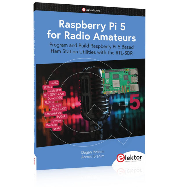
Program and Build Raspberry Pi 5 Based Ham Station Utilities with the RTL-SDR
The RTL-SDR devices (V3 and V4) have gained popularity among radio amateurs because of their very low cost and rich features. A basic system may consist of a USB based RTL-SDR device (dongle) with a suitable antenna, a Raspberry Pi 5 computer, a USB based external audio input-output adapter, and software installed on the Raspberry Pi 5 computer. With such a modest setup, it is possible to receive signals from around 24 MHz to over 1.7 GHz.
This book is aimed at amateur radio enthusiasts and electronic engineering students, as well as at anyone interested in learning to use the Raspberry Pi 5 to build electronic projects. The book is suitable for both beginners through experienced readers. Some knowledge of the Python programming language is required to understand and eventually modify the projects given in the book. A block diagram, a circuit diagram, and a complete Python program listing is given for each project, alongside a comprehensive description.
The following popular RTL-SDR programs are discussed in detail, aided by step-by-step installation guides for practical use on a Raspberry Pi 5:
SimpleFM
GQRX
SDR++
CubicSDR
RTL-SDR Server
Dump1090
FLDIGI
Quick
RTL_433
aldo
xcwcp
GPredict
TWCLOCK
CQRLOG
klog
Morse2Ascii
PyQSO
Welle.io
Ham Clock
CHIRP
xastir
qsstv
flrig
XyGrib
FreeDV
Qtel (EchoLink)
XDX (DX-Cluster)
WSJT-X
The application of the Python programming language on the latest Raspberry Pi 5 platform precludes the use of the programs in the book from working on older versions of Raspberry Pi computers.
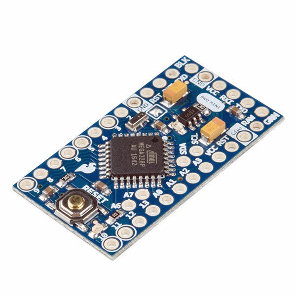
The Arduino Pro Mini is a microcontroller board based on the ATmega328P.
It has 14 digital input/output pins (of which 6 can be used as PWM outputs), 6 analog inputs, an on-board resonator, a reset button, and holes for mounting pin headers. A six pin header can be connected to an FTDI cable or SparkFun breakout board to provide USB power and communication to the board.
The Arduino Pro Mini is intended for semi-permanent installation in objects or exhibitions. The board comes without pre-mounted headers, allowing the use of various types of connectors or direct soldering of wires. The pin layout is compatible with the Arduino Mini.
The Arduino Pro Mini was designed and is manufactured by SparkFun Electronics.
Specifications
Microcontroller
ATmega328P
Board Power Supply
5-12 V
Circuit Operating Voltage
5 V
Digital I/O Pins
14
PWM Pins
6
UART
1
SPI
1
I²C
1
Analog Input Pins
6
External Interrupts
2
DC Current per I/O Pin
40 mA
Flash Memory
32 KB of which 2 KB used by bootloader
SRAM
2 KB
EEPROM
1 KB
Clock Speed
16 MHz
Dimensions
18 x 33.3 mm (0.7 x 1.3")
Downloads
Eagle files
Schematics
... qui sèchent les cours mais soudent sans se brûler les doigts
Par où commencer pour débuter en électronique ? Vais-je m'égarer en explorant l'internet ? Il regorge de schémas, mais sont-ils fiables ? Me faut-il un livre avec des montages simples ou plutôt un livre sur les composants ?
Après trente ans de pratique, l'auteur de ce livre, resté l'éternel débutant qui réalisait lui-même son premier montage des l'âge de dix ans, partage ici sa soif toujours vive d'apprendre. Fin pédagogue, il guide les débutants et répond aux questions que trop de livres laissent en suspens : « Quel type de fer à souder acheter ? »... « Un multimètre à 5 € peut-il suffire ? »... « Un oscilloscope est-il indispensable ? »... « Peut-on installer son montage dans une boîte à cigares ? »...
Rémy Mallard démystifie l'électronique en n'utilisant que ce qu'il vous faut de théorie pour aborder joyeusement la pratique sans risque de faire de grosses bêtises. Vous apprendrez à identifier les composants et leur rôle (résistances, condensateurs, bobines, diodes, transistors, relais, commutateurs...) mais aussi à les récupérer, les tester et les ranger. Bientôt vous saurez lire un schéma, choisir vos outils et mettre en boîte vos montages. Rémy connaît toutes les astuces et vous révèle les pratiques à éviter.
La matière de cet ouvrage, ce sont des montages simples et ludiques, réalisables sur des plaques d'expérimentation sans soudure: sirène, orgue, chenillard lumineux, interrupteur photosensible, thermomètre, alarme, générateur de picotements, indicateur de niveau de liquide, clignotant à vitesse variable selon la lumière ambiante, indicateur à fenêtre programmable, minuterie avec préavis d'extinction, chenillard de style K2000 (lumineux et sonore), gradateur de lumière à commande infrarouge...
Vous commencerez par le code des couleurs et finirez par programmer des PIC !
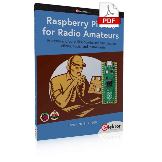
Program and build RPi Pico-based ham station utilities, tools, and instruments
Although much classical HF and mobile equipment is still in use by large numbers of amateurs, the use of computers and digital techniques has now become very popular among amateur radio operators. Nowadays, anyone can purchase a €5 Raspberry Pi Pico microcontroller board and develop many amateur radio projects using the “Pico” and some external components. This book is aimed at amateur radio enthusiasts, Electronic Engineering students, and anyone interested in learning to use the Raspberry Pi Pico to shape their electronic projects. The book is suitable for beginners in electronics as well as for those with wide experience.
Step-by-step installation of the MicroPython programming environment is described. Some knowledge of the Python programming language is helpful to be able to comprehend and modify the projects given in the book. The book introduces the Raspberry Pi Pico and gives examples of many general-purpose, software-only projects that familiarize the reader with the Python programming language. In addition to the software-only projects tailored to the amateur radio operator, Chapter 6 in particular presents over 36 hardware-based projects for “hams”, including:
Station mains power on/off control
Radio station clock
GPS based station geographical coordinates
Radio station temperature and humidity
Various waveform generation methods using software and hardware (DDS)
Frequency counter
Voltmeter / ammeter / ohmmeter / capacitance meter
RF meter and RF attenuators
Morse code exercisers
RadioStation Click board
Raspberry Pi Pico based FM radio
Using Bluetooth and Wi-Fi with Raspberry Pi Pico
Radio station security with RFID
Audio amplifier module with rotary encoder volume control
Morse decoder
Using the FS1000A TX-RX modules to communicate with Arduino
A Practical Guide to Tube Electronics
Vacuum tubes continue to exert a special fascination. Their long-lasting operation, robustness, and characteristic behavior fundamentally distinguish them from modern semiconductor technology. Despite their age, tubes are by no means merely historical components; they are still used today in audio technology, measurement technology, and especially in hobbyist applications.
This book is aimed at electronics enthusiasts and hobbyists who want to not only learn about and understand vacuum tubes in theory, but also use them in practice. It conveys the fundamentals of tube technology, explains the different designs and designations, shows typical circuits, and addresses power supplies, measurements, and safety-related aspects. The focus is on practical explanations and realistic examples from the workshop. Numerous tips help you avoid typical mistakes, build circuits, and understand tube devices and their construction. Basic knowledge of electronics is assumed.
Vacuum Tubes: A Practical Guide to Tube Electronics offers an accessible and thorough introduction to tube technology – factual, comprehensible, and with a clear focus on practical applications.
Open-Source-Code mit Arduino IDE und PlatformIO
Autonomes Fahren: GPS, Accelerometer, Gyroskop
PS3-Controller
Mikrocontroller wie der Arduino und Einplatinenrechner wie der Raspberry Pi haben sich zu beliebten Komponenten entwickelt. Dritter im Bunde ist der ESP32 der Firma Espressif. Mikrocontroller dieser Baureihe zeichnen sich durch eine Vielzahl implementierter Funktionen aus, die bei einem Arduino konventioneller Prägung mit einem Atmel-AVR-Mikrocontroller erst mit weiterer Hardware möglich sind. Prominentes Beispiel sind hier die WiFi- und Bluetooth-Funktionalitäten. Gegenüber einem Raspberry Pi zeichnen sie sich durch einen deutlich geringeren Preis aus.
Allgemeine Informationen für die Realisierung eines Roboterauto-Projekts mit dem ESP32 sind leicht zu finden. Dabei handelt es sich aber oft nur um Ausführungen zu einem Teilaspekt, ohne inhaltliche oder funktionale Abstimmung. So ist nicht nur die Beschaffung der benötigten Informationen mühselig und zeitaufwändig, sie kann auch außerordentlich fehlerträchtig sein.
Ansatzpunkt dieses Buches ist, diese Lücke zu schließen. Es geht auf verschiedene Möglichkeiten eines Chassis ein, vermittelt nötige Kenntnisse und führt schrittweise von einer einfachen Motorsteuerung zu einem komplexen sensor- und sprachgesteuerten Roboterauto. Hacks rund um GPS und eine PlayStation 3 runden die Sache ab.
Inhalt
Bei der Reihenfolge der Kapitel wurde versucht – beginnend bei der Darstellung von grundlegenden Informationen – über die Lösung einfacher Aufgaben zu etwas anspruchsvolleren Techniken zu führen.
Der Mikrocontroller ESP32
Die Software erstellen
Die Stromversorgung
Rund um die Hardware
Das Chassis
Der Gleichstrommotor
Kabellose Steuerung über WiFi
Mit Sensoren Hindernisse erkennen
Eine eigene Roboterauto-App
Servo und Lichtsensor
GPS
Accelerometer / Gyroskop
PS3-Controller
Roboterauto-App
Hinweis zur Software
Die Dateien haben das Suffix (.cpp). Grund ist die Entwicklung mit PlatformIO. Mit Copy & Paste sollten sie auch in der Arduino-IDE verwendet werden können.
The Internet of Things is rapidly gaining interest, and that has fueled the development of the Edison. A tiny computer, the size of a postage stamp, with a lot of power and built-in wireless communication capabilities.
In this eBook we will help you get up-to-speed with the Edison, by installing the software both on the Edison as well as on your Windows PC. We will use the Edison Arduino break-out board because it is easy to work with. We will discuss Linux, Arduino C++ and Python, and show examples of how the Edison can interface with other hardware. We will use Wi-Fi and Bluetooth to set up wireless connections, and show you a trick to program sketches over Wi-Fi.
Once you have completed this book your Edison will be up and running with the latest software version, and you will have sufficient knowledge of both hardware and software to start making your own applications. You will even be able to program the Edison over USB and wireless both in Arduino C++ and Python.
This is not a projects eBook, but a toolbox that will allow you to explore the wonderful world of the Intel Edison!
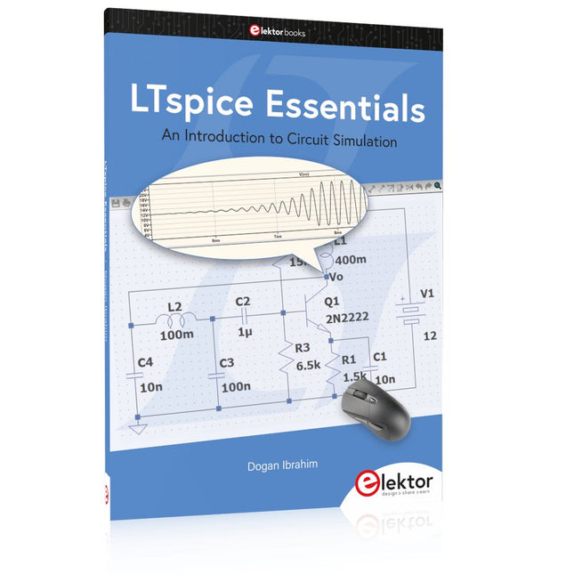
An Introduction to Circuit Simulation
LTspice, developed by Analog Devices, is a powerful, fast, and free SPICE simulator, schematic capture, and waveform viewer with a large database of components supported by SPICE models from all over the world. Drawing a schematic in LTspice is easy and fast. Thanks to its powerful graphing features, you can visualize the voltages and currents in a circuit, and also the power consumption of its components and much more.
This book is about learning to design and simulate electronic circuits using LTspice. Among others, the following topics are treated:
DC and AC circuits
Signal diodes and Zener diodes
Transistor circuits including oscillators
Thyristor/SCR, diac, and triac circuits
Operational amplifier circuits including oscillators
The 555 timer IC
Filters
Voltage regulators
Optocouplers
Waveform generation
Digital logic simulation including the 74HC family
SPICE modeling LTspice is a powerful electronic circuit simulation tool with many features and possibilities. Covering them all in detail is not possible in a book of this size. Therefore, this book presents the most common topics like DC and AC circuit analysis, parameter sweeping, transfer functions, oscillators, graphing, etc. Although this book is an introduction to LTspice, it covers most topics of interest to people engaged in electronic circuit simulation.
The book is aimed at electronic/electrical engineers, students, teachers, and hobbyists. Many tested simulation examples are given in the book. Readers do not need to have any computer programming skills, but it will help if they are familiar with basic electronic circuit design and operation principles. Readers who want to dive deeper can find many detailed tutorials, articles, videos, design files, and SPICE circuit models on the Internet.
All the simulation examples used in the book are available as files at the webpage of this book. Readers can use these example circuits for learning or modify them for their own applications.
Praktischer Einstieg mit Arduino, GnuRadio und FPGA
Das Thema „Software Defined Radio“ ist facettenreich: Neben der Schaltungstechnik ist auch eine Einarbeitung in die Programmierung von Hardware und PC wichtig. Ein schrittweises Vorgehen erleichtert Ihnen den Einstieg. Mit dem im Buch vorgestellten modularen „RF Bricks“-Konzept werden Sie zum Architekten Ihrer Signalkette. Auf einem Chassis angeordnet gewährleisten die Module einen soliden und gut abgeschirmten Aufbau, den Sie einfach verändern und mit eigenen Ideen anreichern können.
Der skalierbare Aufbau bildet Ihr Blockschaltbild auch mechanisch ab – die so gewonnene Übersicht kann in der Aus- und Weiterbildung nützlich sein. Ein Arduino in Ihrem Chassis kommuniziert nach einigen Anpassungen mit üblichen SDR-Programmen, z. B. SDRCPP, GQRX und CubicSDR auf einer Linux-Plattform. Damit können Sie Ihren Empfänger direkt per Mausklick abstimmen.
Wenn Sie Blockschaltbilder mögen, ist GnuRadio ein natürlicher Partner der „RF Bricks“. Mit einem selbst programmierten Python-Block gelingt Ihnen in GnuRadio die Fernsteuerung Ihres Empfängers. Im GnuRadio-Universum können Sie Ihre GUI stufenweise ausbauen, behalten dabei aber immer volle Kontrolle über die inneren Abläufe des Programms.
Mit einem FPGA können zeitaufwändige Operationen auch direkt in die Hardware verlagert werden. Sie bauen stufenweise einen Doppelsuperhet auf und entwickeln die Filterkoeffizienten für FIR-Filter mit Scilab. Das in VHDL realisierte Weaver-Schema rundet diesen Empfänger ab, der mit hoher Empfindlichkeit und Dynamik aufwarten kann.
Mit dem gewonnen Überblick und Ihrer neuen Hardware können Sie die einzelnen Aspekte des Themenkomplexes SDR beliebig weiter vertiefen.
Downloads
Software
PIC und AVR verstehen
In diesem Buch werden wir uns ausschließlich mit 8-Bit-Mikrocontrollern beschäftigen, und zwar mit Mikrocontrollern der 8-Bit-PIC- und der 8-Bit-AVR-Mikrocontroller-Linien. Bei der PIC-Familie handelt es sich dabei um PIC10, PIC12, PIC16 und PIC18; bei der AVR-Familie um ATtiny, ATmega und ATxmega. Die vorgestellten 8-Bit-Chips sind für sehr viele Anwendungen vollkommen ausreichend und preislich auch attraktiv.
Durch die Lektüre des Buches erhalten Sie ein fundiertes Wissen über die genannten 8-Bit-Mikrocontroller, über ihre Architektur, ihre Pinbelegungen und über ihre Programmierung.
Weil wir uns in diesem Buch mit den Grundlagen der Architektur der PICs und AVRs vertraut machen möchten, werden wir auch für alle PIC- und AVR-Anwendungen Assembler einsetzen, denn die Assembler-Sprache erlaubt es, die Technik im Detail kennenzulernen. Wenn man wirklich wissen möchte, was sich im Mikrocontroller abspielt, greift man zu Assembler. Damit hat man die beste Gelegenheit, sehr nah an den Kern zu kommen. Und wenn man schon einen Mikrocontroller-Typ kennengelernt und verstanden hat, ist es bei dem nächsten deutlich einfacher, auch wenn er von einem anderen Hersteller kommt. Bei anderen Programmiersprachen bleibt die Technik immer ziemlich tief versteckt.
Die Assembler-Beispiele sind so einfach gestaltet, dass sie jeder mit den im Buch aufgezeigten Programmiertechniken erstellen kann. Weil es sich um einfache Beispiele handelt, werden wir sie alle auf einer universellen Lochrasterplatine realisieren. Manche sind auch auf einem Experimentier-Breadboard umsetzbar.