
Search results for "fnirsi OR lcr OR p1 OR multi OR function OR transistor OR tester"
-
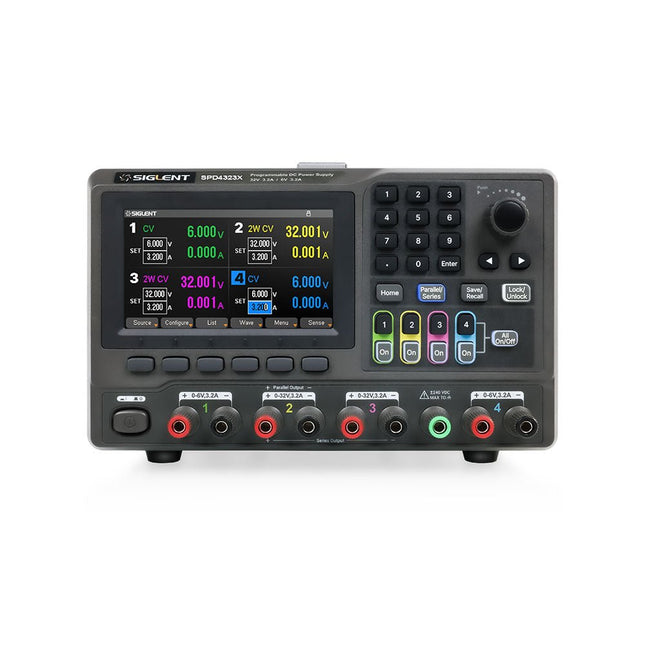
Siglent Siglent SPD4323X 4-ch DC Power Supply (240 W)
The Siglent SPD4323X is a 4-channel DC Linear Programmable Power Supply equipped with a 4.3-inch TFT-LCD display, friendly human-machine interface, and excellent performance indicators. Real-time waveform display provides engineers with an informative user interface. SPD4323X offers a total output power of 240 W with a resolution of 1 mV/1 mA. The maximum voltage and current for each channel are as follows: CH1: 6 V/3.2 A CH2: 32 V/3.2 A CH3: 32 V/3.2 A CH4: 6 V/3.2 A Features Rated output power: 240 W Rated voltage: 32 V, 12 V, 30 V Up to four high-precision power supplies with independent controllable outputs, supporting CH2 and CH3 series and parallel connections Clear graphical interface with waveform and timer display modes 5-digit voltage and current display with minimum resolution of 1 mV, 1 mA Fast output response time: <50us The high current channel support remote voltage compensation sense function. The maximum compensation voltage is 0.6 V Overvoltage protection and overcurrent protection or safe and accurate operation Equipped with a 4.3-inch TFT-LCD display (480 x 272 resolution) USB and LAN standard communication USB-GPIB module is optional Excellent channel density with up to 4 channels in a 3U half rack package Internal data storage for setups and parameters Embedded Web Server with instrument communication that doesn’t require software installation Fully SCPI programming command set support as well as a LabView driver for remote control and system automation Specifications SPD4323X SPD4121X SPD4306X Channel Output CH1: Voltage 0 to 6 V Current 0 to 3.2 ACH2: Voltage 0 to 32 V Current 0 to 3.2 ACH3: Voltage 0 to 32 V Current 0 to 3.2 ACH4: Voltage 0 to 6 V Current 0 to 3.2 A CH1: Voltage 0 to 15 V Current 0 to 1.5 ACH2: Voltage 0 to 12 V Current 0 to 10 ACH3: Voltage 0 to 12 V Current 0 to 10 ACH4: Voltage 0 to 15 V Current 0 to 1.5 A CH1: Voltage 0 to 15 V Current 0 to 1.5 ACH2: Voltage 0 to 30 V Current 0 to 6 ACH3: Voltage 0 to 30 V Current 0 to 6 ACH4: Voltage 0 to 15 V Current 0 to 1 A Resolution 1 mV, 1 mA 1 mV, 1 mA 1 mV, 1 mA Setting Accuracy Voltage: ±(0.03% of reading+10) mV, Current: ±(0.3% of reading+10) mA Voltage: ±(0.03% of reading+10) mV, Current: ±(0.3% of reading+10) mA Voltage: ±(0.03% of reading+10) mV, Current: ±(0.3% of reading+10) mA Readback Accuracy Voltage: ±(0.03% of reading+10) mV, Current: ±(0.3% of reading+10) mA Voltage: ±(0.03% of reading+10) mV, Current: ±(0.3% of reading+10) mA Voltage: ±(0.03% of reading+10) mV, Current: ±(0.3% of reading+10) mA Display 4.3" TFT-LCD 5-digit voltage and current display 4.3" TFT-LCD 5-digit voltage and current display 4.3" TFT-LCD 5-digit voltage and current display Output power 240 W 285 W 400 W Included 1x Siglent SPD4323X Power Supply 1x Power cord (EU) 1x Output test cord (3 A) 1x USB cable 1x Quick start guide Downloads Datasheet Manual Quick start
€ 762,30
-

Elektor Digital Elektor Januari/Februari 2025 (PDF) NL
Elektor GREEN en GOLD leden kunnen deze uitgave hier downloaden. Nog geen lid? Klik hier om een lidmaatschap af te sluiten. DHZ-accusysteem voor zonne-energiebouw uw eigen energieopslag voor zonnepanelen Simulator voor zonnepanelentest en optimaliseer MPP-trackers en omvormers De STM32 Edge-AI-ContestOntdek de nieuwe STM32N6 en ding mee naar € 5000! Vergroten van de bandgapdaarom is er zoveel interesse in SiC en GaN Powerbank voor noteboekgeef uw oude laptop een tweede leven Medische robotshet overwinnen van technische en regelgevende barrières Vorstbescherming voor fruitbomenmet temperatuurlogger Het analoge dingde Arduino onder de analoge computers? Zuinige relaisdriverspaart 90% spoelstroom Verbetering van de ET5410A+ DC-belastingblijf koel en stil electronica 2024een terugblik Elektromagnetische compatibiliteitEMC in een notendop! Alle begin......filtert actief Reduceer vermogensverlies met seriecondensatorenslim gebruik van capacitieve reactantie De betaalbare MCP4725 12-bit digitaal/analoog-omzetterEEPROM-functie zorgt voor veilig inschakelgedrag FNIRSI LCR-ST1 smart LCR-meetpincet Raspberry Pi-gebaseerd test- en meetlabals eerste: de ADC Elektronische belastingweerstandmet onderdelen die u waarschijnlijk hebt liggen 2025: een AI-odysseeenkele projecten voor het nieuwe jaar Project-update: AmpVolt v2.0100 ampère en meer! Project 2.0correcties, updates en brieven van lezers Ethische transparantie ontsluierdinzichten uit het Ethics in Electronics 2024 onderzoek Audio DSP FX Processor Boarddeel 2: toepassingen maken
€ 9,95
-

Sensepeek Sensepeek 6024 SQ500 (500 MHz handsfree Oscilloscope Probe)
The SQ series of handsfree probes from Sensepeek have a lower point of gravity making them even more stable compared with the original SP series of handsfree probes. All probes in the SQ series are also insulated and can be used handheld as any traditional probe but their full potential is used when measuring handsfree. The SQ series of oscilloscope probes also includes more ground options, have probe tip protection, longer cable and support for oscilloscopes with automatic scaling (10:1). All the loved features of handsfree measurement, exchangeable fine pitch spring tipped test needle, color-coded cable holders and the minimalistic design is maintained to make traditional sized and handheld probes obsolete. Both length and weight of the SQ probes are perfectly balanced to be used with PCBite PCB holders and base plate which is a must for handsfree function. Features Passive 10:1 probe with support for oscilloscopes with automatic scaling Spring-loaded test needle for fine pitch measurements Multiple ground options Color coded cable holders Probe tip protection Insulated, can be used handheld Improved probe holder for handsfree measurement when used with PCBite PCB holders Included 1x SQ500 500 MHz probe with spring tipped test needle 1x SQ probe holder for handsfree measurement 1x Testhook with detachable cables (5 cm & 10 cm) for convenient ground connection 1x Alligator cable for convenient ground connection 1x Standard ground spring, for handheld measurements at rated bandwidth 1x Unique ground spring, for total handsfree measurements at rated bandwidth 1x Set of color coded cable holders (4 colors) 1x Probe tip protection 1x Extra test needle Downloads User Guide SQXX0 Rev1.1
€ 131,89
-

FNIRSI FNIRSI TMP-610S (3-in-1) Multimeter (60,000 Counts) + Oscilloscope + Signal Generator
The FNIRSI TMP-610S is a compact 3-in-1 test instrument combining a True RMS multimeter, 10 MHz oscilloscope, and 50 kHz DDS signal generator. It is designed for electronics troubleshooting, circuit testing, and development in the lab or on the go. The multimeter offers 60,000-count resolution and supports voltage, current, resistance, capacitance, frequency, temperature, diode, and continuity measurements. The integrated oscilloscope provides real-time waveform analysis at up to 48 MSa/s, while the signal generator supports 13 waveform types with adjustable frequency, amplitude, and duty cycle. A 3.5-inch IPS touchscreen, smart auto-scan, Bluetooth connectivity for DMM functions, waveform storage, USB export, and a 3,000 mAh rechargeable battery make the TMP-610S a versatile all-in-one tool for electronics professionals and enthusiasts. Features 3-in-1 Design: DMM + Oscilloscope + Signal Generator 60,000-Count True RMS High-Precision Measurement 10 MHz Oscilloscope with 48 MSa/s Sampling Rate Bluetooth App Sync (Multimeter Function Only) 3.5-inch Smart Touchscreen with Multiple Display Modes 50 kHz DDS Signal Generator with 13 Waveforms Built-in Fuse for Easy Replacement Specifications Multimeter Function Range Accuracy DC voltage 600mV/6V/60V/600V/1000V ±(0.03%+5d) AC voltage 600mV/6V/60V /600V/750V ±(0.3%+15d) DC current 600uA/6000uA/60mA/600mA ±(0.15%+5d) 6A/10A ±(0.2%+5d) AC current 600uA/6000uA/60mA/600mA ±(0.5%+15d) 6A/10A ±(0.75%+15d) Resistance 600Ω/6KΩ/60KΩ/600KΩ/6MΩ ±(0.1%+5d) 60MΩ ±(0.2%+10d) Capacitance 60nF/600nF/6uF/60uF ±(2.5%+30d) 600uF/6mF/60mF ±(3.5%+30d Frequency 10 Hz~60 MHz ±(0.01%+5d) Temperature -40℃~1000℃ ±(1.0%+5℃) Continuity 0Ω~1KΩ ±(0.2%+5d) Diode 0V~3.0V, 0Ω~1 Ω ±(1%+5d) AC frequency response 10KHz / Oscilloscope Real-time Sampling Rate 48 MSa/s Analog Bandwidth 10 MHz Input Impedance 1MΩ Coupling Mode AC/DC Test Voltage Range 1:1 Probe - 80Vpp (±40V) 10:1 Probe - 800Vpp (±400V) Vertical Sensitivity 10mV/div~10V/div Vertical Displacement Adjustable with indication Horizontal Time Base Range 50 ns ~ 20 s Trigger Mode Auto, Normal, Single Trigger Type Rising, Falling, 50% Trigger Level Adjustable with indication Measurement Parameters Freq, Period, +Duty, ‒Duty, +Width, ‒Width, Max, Min, P‒P, Amp, RMS, Avg Persistence Off / 500ms / 1s / ∞ Cursor Measurement Yes Waveform Screenshot Saving Yes Signal Generator Output Waveform Supports 13 waveform types Frequency 0~50kHz Amplitude 0.0V~3.0V Duty Cycle 0~100%, adjustable for Square and Sawtooth waves Included 1x FNIRSI TMP-610S Multimeter + Oscilloscope + Signal Generator 1x P6100 Probe 1x Adapter 2x Alligator Clips 2x Multimeter Probes Probe Accessories 1x Storage Bag 1x USB-C Cable 1x Manual Downloads Manual
-

Elektor Bundles Mikrocontroller-Praxiskurs für Arduino-Einsteiger (Bundle)
Mit dem Elektor Arduino Nano Trainingsboard (MCCAB) eigene Projekte realisieren Der Mikrocontroller ist das wohl faszinierendste Teilgebiet der Elektronik, denn aufgrund der Vielzahl von Funktionen, die er auf seinem Chip vereinigt, ist er für den Entwickler ein universelles Multi-Tool zur Realisierung seiner Projekte. Praktisch jedes Gerät des täglichen Gebrauchs wird heute von einem Mikrocontroller gesteuert. Für einen elektronischen Laien blieb es aufgrund der Komplexität bisher allerdings ein Wunschtraum, eigene Ideen mit einem Mikrocontroller zu realisieren. Das Arduino-Konzept hat den Einsatz von Mikrocontrollern weitgehend vereinfacht, sodass jetzt auch Laien eigene Elektronik-Ideen mit einem Mikrocontroller verwirklichen können. Buch & Hardware im Bundle: 'Learning by Doing' Dieses im Bundle mitgelieferte Buch (im großen A4-Format) zeigt, wie man auch ohne große Erfahrung in Elektronik und Programmiersprachen eigene Projekte mit einem Mikrocontroller realisieren kann. Es ist ein Mikrocontroller-Praxiskurs für Einsteiger, denn nach einem Überblick über die Interna des Mikrocontrollers und einer Einführung in die Programmiersprache C liegt der Schwerpunkt des Kurses auf den praktischen Übungen. Der Leser eignet sich die erforderlichen Kenntnisse durch 'Learning by Doing' an: in dem umfangreichen Praxisteil mit 12 Projekten und 46 Übungen wird das im vorderen Teil des Buches Gelernte mit vielen Beispielen unterlegt. Die Übungen sind dabei so aufgebaut, dass der Bearbeiter eine Aufgabenstellung erhält, die er mit seinem im Theorieteil des Buches aufgebauten Wissen löst. Für jede Übung gibt es anschließend eine ausführlich erklärte und kommentierte Musterlösung, die dem Bearbeiter bei Problemen weiterhilft und die er mit seiner eigenen Lösung vergleichen kann. Arduino IDE In der Arduino IDE, einer Software-Entwicklungsumgebung, die kostenlos auf den eigenen PC heruntergeladen werden kann und die das gesamte Softwarepaket enthält, das für ein eigenes Mikrocontroller-Projekt benötigt wird, schreibt der Bearbeiter mit dem Editor der IDE seine Programme („Apps“) in der Programmiersprache C. Der in die Arduino IDE integrierte Compiler übersetzt sie in die Bits und Bytes, die der Mikrocontroller versteht und die dann über ein USB-Kabel in den Speicher des Mikrocontrollers auf dem Elektor Arduino Nano Trainingsboard (MCCAB) geladen werden. Externe Sensoren, Motoren oder Baugruppen abfragen oder steuern Das Elektor Arduino Nano Trainingsboard (MCCAB) enthält neben einem Mikrocontrollermodul Arduino Nano alle für die Übungen benötigten Bauteile wie Leuchtdioden, Schalter, Taster, akustische Signalgeber usw. Auch externe Sensoren, Motoren oder Baugruppen können mit diesem Mikrocontroller-Übungssystem abgefragt oder gesteuert werden. Technische Daten (Arduino Nano Trainingsboard MCCAB) Stromversorgung Über die USB-Verbindung des zur Erstellung der Programme sowieso angeschlossenen PCs oder ein externes Netzteil (nicht im Lieferumfang enthalten) Betriebsspannung +5 Vcc Eingangsspannung Alle Eingänge 0 V bis +5 V VX1 und VX2 +8 V bis +12 V (nur bei Verwendung eines externen Netzteils) Mikrocontrollermodul Arduino Nano Hardwareperipherie LCD 2x16 Zeichen Potenziometer P1 & P2 JP3: Auswahl der Betriebsspannung von P1 & P2 Verteiler SV4: Verteiler für die BetriebsspannungenSV5, SV6: Verteiler für die Ein-/Ausgänge des Mikrocontrollers Schalter und Taster RESET-Taster auf dem Arduino Nano-Modul6x Tastschalter K1 … K66x Schiebeschalter S1 … S6JP2: Verbindung der Schalter mit den Eingängen des Mikrocontrollers Summer Piezo-Summer Buzzer1 mit Steckbrücke auf JP6 Leuchtanzeigen LED L auf dem Arduino Nano-Modul, verbunden mit GPIO D1311x LED: Zustandsanzeige für die Ein-/AusgängeJP6: Verbindung der LEDs LD10 … LD20 mit den GPIOs D2 … D12 Serielle SchnittstellenSPI & I²C JP4: Auswahl des Signals an Pin X der SPI-Steckerleiste SV12SV9 bis SV12: SPI-Interface (3,3 V/5 V) bzw. I²C-Interface Schaltausgang für externe Geräte SV1, SV7: Schaltausgang (maximal +24 V/160 mA, extern zugeführt)SV2: 2x13 Pins zum Anschluss externer Module 3x3 LED-Matrix (9 rote LEDs) SV3: Spalten der 3x3 LED-Matrix (Ausgänge D6 … D8)JP1: Verbindung der Reihen mit den GPIOs D3 … D5 Software Library MCCABLib Steuerung der Hardware-Komponenten (Schalter, Taster, Leuchtdioden, 3x3 LED-Matrix, Summer) auf dem MCCAB Trainingsboard Betriebstemperatur bis +40 °C Abmessungen 100 x 100 x 20 mm Technische Daten (Arduino Nano) Mikrocontroller ATmega328P Architektur AVR Betriebsspannung 5 V Flashspeicher 32 KB, davon 2 KB vom Bootloader belegt SRAM 2 KB Taktfrequenz 16 MHz Analoge IN-Pins 8 EEPROM 1 KB DC-Strom pro I/O-Pin 40 mA an einem I/O-Pin, insgesamt maximal 200 mA an allen Pins gemeinsam Eingangsspannung 7-12 V Digitale I/O-Pins 22 (6 davon sind PWM-fähig) PWM-Ausgänge 6 Stromverbrauch 19 mA Abmessungen 18 x 45 mm Gewicht 7 g Lieferumfang Elektor Arduino Nano MCCAB Trainingsboard Arduino Nano Buch: Mikrocontroller-Praxiskurs für Arduino-Einsteiger
-

Elektor Janvier/Février 2025 (FR)
Le téléchargement intégral de ce numéro est disponible pour nos membres GOLD et GREEN sur le site Elektor Magazine ! Pas encore membre ? Cliquez ici. stockage de l’énergieRéalisez votre propre stockage d’énergie pour réseau de panneaux photovoltaïques simulateur de panneau solaireUne solution pour tester et optimiser les trackers MPP et les onduleurs le concours STM32 Edge AIDécouvrez le STM32N6 et gagnez les 5000 € du concours ! Matériaux à large bande interditePourquoi y a-t-il un tel intérêt pour le SiC et le GaN ? batterie externe pour ordinateur portableProlongez la durée de vie de votre vieil ordinateur portable robots médicauxSurmonter les obstacles techniques et réglementaires prévention du gel pour les vergersavec enregistrement des températures The Analog ThingL'Arduino de l’ordinateur analogique ? commande de relais à faible consommation d'énergieÉconomiser 90% de la puissance de commande amélioration de la charge DC ET5410A+pour un meilleur refroidissement et moins de bruit electronica 2024 : rétrospective compatibilité électromagnétiqueLa CEM en quelques mots ! démarrer en électronique......Filtres actifs réduisez les pertes des chutes de tension avec des condensateursprofitez astucieusement de la réactance capacitive le MCP4725 : un convertisseur numérique-analogique 12 bits pas cheravec une fonction EEPROM pour un comportement sûr au démarrage la pince de test intelligente Fnirsi LCR-ST1 pour CMS labo de test et de mesure personnel basé sur Raspberry PiPour commencer : l'ADC une charge électroniqueUn projet prêt à l'emploi 2025 : l'odyssée de l'IAQuelques projets pour le nouvel an AmpVolt v2.0 : mise à jour100 A et plus ! projet 2.0Corrections, mises à jour et courrier des lecteurs transparence éthiqueCe que révèle l’enquête réalisée par Ethics in Electronics carte Elektor Audio DSP FX Processor (2)Création d'applications
€ 15,50


