
Search results for "sparkfun OR freesoc2 OR development OR board OR psoc5lp"
-
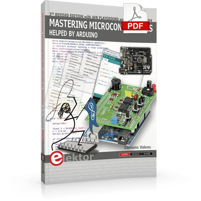
Elektor Digital Mastering Microcontrollers Helped by Arduino (3rd Edition) | E-book
Third, extended and revised edition with AVR Playground and Elektor Uno R4 Arduino boards have become hugely successful. They are simple to use and inexpensive. This book will not only familiarize you with the world of Arduino but it will also teach you how to program microcontrollers in general. In this book theory is put into practice on an Arduino board using the Arduino programming environment. Some hardware is developed too: a multi-purpose shield to build some of the experiments from the first 10 chapters on; the AVR Playground, a real Arduino-based microcontroller development board for comfortable application development, and the Elektor Uno R4, an Arduino Uno R3 on steroids. The author, an Elektor Expert, provides the reader with the basic theoretical knowledge necessary to program any microcontroller: inputs and outputs (analog and digital), interrupts, communication busses (RS-232, SPI, I²C, 1-wire, SMBus, etc.), timers, and much more. The programs and sketches presented in the book show how to use various common electronic components: matrix keyboards, displays (LED, alphanumeric and graphic color LCD), motors, sensors (temperature, pressure, humidity, sound, light, and infrared), rotary encoders, piezo buzzers, pushbuttons, relays, etc. This book will be your first book about microcontrollers with a happy ending! This book is for you if you are a beginner in microcontrollers, an Arduino user (hobbyist, tinkerer, artist, etc.) wishing to deepen your knowledge,an Electronics Graduate under Undergraduate student or a teacher looking for ideas. Thanks to Arduino the implementation of the presented concepts is simple and fun. Some of the proposed projects are very original: Money Game Misophone (a musical fork) Car GPS Scrambler Weather Station DCF77 Decoder Illegal Time Transmitter Infrared Remote Manipulator Annoying Sound Generator Italian Horn Alarm Overheating Detector PID Controller Data Logger SVG File Oscilloscope 6-Channel Voltmeter All projects and code examples in this book have been tried and tested on an Arduino Uno board. They should also work with the Arduino Mega and every other compatible board that exposes the Arduino shield extension connectors. Please note For this book, the author has designed a versatile printed circuit board that can be stacked on an Arduino board. The assembly can be used not only to try out many of the projects presented in this book but also allows for new exercises that in turn provide the opportunity to discover new techniques. Also available is a kit of parts including the PCB and all components. With this kit you can build most of the circuits described in the book and more. Datasheets Active Components Used (.PDF file): ATmega328 (Arduino Uno) ATmega2560 (Arduino Mega 2560) BC547 (bipolar transistor, chapters 7, 8, 9) BD139 (bipolar power transistor, chapter 10) BS170 (N-MOS transistor, chapter 8) DCF77 (receiver module, chapter 9) DS18B20 (temperature sensor, chapter 10) DS18S20 (temperature sensor, chapter 10) HP03S (pressure sensor, chapter 8) IRF630 (N-MOS power transistor, chapter 7) IRF9630 (P-MOS power transistor, chapter 7) LMC6464 (quad op-amp, chapter 7) MLX90614 (infrared sensor, chapter 10) SHT11 (humidity sensor, chapter 8) TS922 (dual op-amp, chapter 9) TSOP34836 (infrared receiver, chapter 9) TSOP1736 (infrared receiver, chapter 9) MPX4115 (analogue pressure sensor, chapter 11) MCCOG21605B6W-SPTLYI (I²C LCD, chapter 12) SST25VF016B (SPI EEPROM, chapter 13) About the author Clemens Valens, born in the Netherlands, lives in France since 1997. Manager at Elektor Labs and Webmaster of ElektorLabs, in love with electronics, he develops microcontroller systems for fun, and sometimes for his employer too. Polyglot—he is fluent in C, C++, PASCAL, BASIC and several assembler dialects—Clemens spends most of his time on his computer while his wife, their two children and two cats try to attract his attention (only the cats succeed). Visit the author’s website: www.polyvalens.com.Authentic testimony of Hervé M., one of the first readers of the book:'I almost cried with joy when this book made me understand things in only three sentences that seemed previously completely impenetrable.'
€ 34,95
Members: € 31,46
-

Elektor Digital The BeagleY-AI Handbook (E-book)
A Practical Guide to AI, Python, and Hardware Projects Welcome to your BeagleY-AI journey! This compact, powerful, and affordable single-board computer is perfect for developers and hobbyists. With its dedicated 4 TOPS AI co-processor and a 1.4 GHz Quad-core Cortex-A53 CPU, the BeagleY-AI is equipped to handle both AI applications and real-time I/O tasks. Powered by the Texas Instruments AM67A processor, it offers DSPs, a 3D graphics unit, and video accelerators. Inside this handbook, you‘ll find over 50 hands-on projects that cover a wide range of topics—from basic circuits with LEDs and sensors to an AI-driven project. Each project is written in Python 3 and includes detailed explanations and full program listings to guide you. Whether you‘re a beginner or more advanced, you can follow these projects as they are or modify them to fit your own creative ideas. Here’s a glimpse of some exciting projects included in this handbook: Morse Code Exerciser with LED or BuzzerType a message and watch it come to life as an LED or buzzer translates your text into Morse code. Ultrasonic Distance MeasurementUse an ultrasonic sensor to measure distances and display the result in real time. Environmental Data Display & VisualizationCollect temperature, pressure, and humidity readings from the BME280 sensor, and display or plot them on a graphical interface. SPI – Voltmeter with ADCLearn how to measure voltage using an external ADC and display the results on your BeagleY-AI. GPS Coordinates DisplayTrack your location with a GPS module and view geographic coordinates on your screen. BeagleY-AI and Raspberry Pi 4 CommunicationDiscover how to make your BeagleY-AI and Raspberry Pi communicate over a serial link and exchange data. AI-Driven Object Detection with TensorFlow LiteSet up and run an object detection model using TensorFlow Lite on the BeagleY-AI platform, with complete hardware and software details provided.
€ 34,95
Members: € 31,46
-
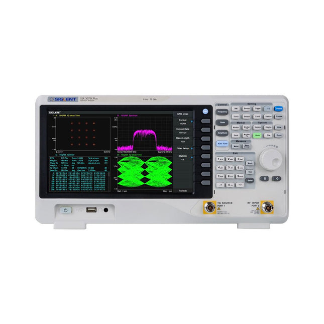
Siglent Siglent SSA3075X Plus Spectrum Analyzer (9 kHz – 7.5 GHz)
The Siglent SSA3075X Plus spectrum analyzer is a powerful and flexible tool for RF signal and network analysis. With a frequency range of 7.5 GHz, the analyzer delivers reliable automatic measurements and multiple modes of operation: spectrum analyzer the base, optional functions include RF power measurement, vector signal modulation analysis, reflection measurement, and EMI test. Applications include broadcast monitoring/evaluation, site surveying, S-parameter measurement, analog/digital modulation analysis, EMI pre-compliance test, research and development, education, production, and maintenance. Features Spectrum Analyzer Frequency Range from 9 kHz to 7.5 GHz –165 dBm/Hz Displayed Average Noise Level (Typ.) –98 dBc/Hz. @ 10 kHz Offset Phase Noise (1 GHz, Typ.) Level Measurement Uncertainty <0.7 dB (Typ.) 1 Hz Minimum Resolution Bandwidth (RBW) Preamplifier (Std.) Tracking Generator (incl. free of charge) Analog and Digital Signal Modulation Analysis Mode (opt.) Reflection Measurement Kit (opt.) EMI Filter and Quasi-Peak Detector Kit (opt.) Advanced Measurement Kit (opt.) 10.1-inch Multi-Touch Screen , Mouse and Keyboard supported Web Browser Remote Control on PC and Mobile Terminals and File Operation Specifications SSA3015X Plus SSA3021X Plus SSA3032X Plus SSA3075X Plus Frequency Range 9 kHz ~ 1.5 GHz 9 kHz ~ 2.1 GHz 9 kHz ~ 3.2 GHz 9 kHz ~ 7.5 GHz Resolution Bandwidth 1 Hz ~ 1 MHz 1 Hz ~ 1 MHz 1 Hz ~ 1 MHz 1 Hz ~ 3 MHz Phase Noise <–99 dBc/Hz <–98 dBc/Hz <–98 dBc/Hz <–98 dBc/Hz Total Amplitude Accuracy <1.2 dB <0.7 dB <0.7 dB <0.7 dB Display Average Noise Level –156 dBm/Hz –161 dBm/Hz –161 dBm/Hz –165 dBm/Hz Included Siglent SSA3075X Plus spectrum analyzer USB cable Power cord Quick start guide Downloads Datasheet Manual Documentation Firmware
€ 7.875,89
-

Siglent Siglent SSA3032X Plus Spectrum Analyzer (9 kHz – 3.2 GHz)
The Siglent SSA3032X Plus spectrum analyzer is a powerful and flexible tool for RF signal and network analysis. With a frequency range of 3.2 GHz, the analyzer delivers reliable automatic measurements and multiple modes of operation: spectrum analyzer the base, optional functions include RF power measurement, vector signal modulation analysis, reflection measurement, and EMI test. Applications include broadcast monitoring/evaluation, site surveying, S-parameter measurement, analog/digital modulation analysis, EMI pre-compliance test, research and development, education, production, and maintenance. Features Spectrum Analyzer Frequency Range from 9 kHz to 3.2 GHz –161 dBm/Hz Displayed Average Noise Level (Typ.) –98 dBc/Hz. @ 10 kHz Offset Phase Noise (1 GHz, Typ.) Level Measurement Uncertainty <0.7 dB (Typ.) 1 Hz Minimum Resolution Bandwidth (RBW) Preamplifier (Std.) Tracking Generator (incl. free of charge) Analog and Digital Signal Modulation Analysis Mode (opt.) Reflection Measurement Kit (opt.) EMI Filter and Quasi-Peak Detector Kit (opt.) Advanced Measurement Kit (opt.) 10.1-inch Multi-Touch Screen , Mouse and Keyboard supported Web Browser Remote Control on PC and Mobile Terminals and File Operation Specifications SSA3015X Plus SSA3021X Plus SSA3032X Plus SSA3075X Plus Frequency Range 9 kHz ~ 1.5 GHz 9 kHz ~ 2.1 GHz 9 kHz ~ 3.2 GHz 9 kHz ~ 7.5 GHz Resolution Bandwidth 1 Hz ~ 1 MHz 1 Hz ~ 1 MHz 1 Hz ~ 1 MHz 1 Hz ~ 3 MHz Phase Noise <–99 dBc/Hz <–98 dBc/Hz <–98 dBc/Hz <–98 dBc/Hz Total Amplitude Accuracy <1.2 dB <0.7 dB <0.7 dB <0.7 dB Display Average Noise Level –156 dBm/Hz –161 dBm/Hz –161 dBm/Hz –165 dBm/Hz Included Siglent SSA3032X Plus spectrum analyzer USB cable Power cord Quick start guide Downloads Datasheet Manual Documentation Firmware
€ 2.951,19
-

Siglent Siglent SSA3015X Plus Spectrum Analyzer (9 kHz – 1.5 GHz)
The Siglent SSA3015X Plus spectrum analyzer is a powerful and flexible tool for RF signal and network analysis. With a frequency range of 1.5 GHz, the analyzer delivers reliable automatic measurements and multiple modes of operation: spectrum analyzer the base, optional functions include RF power measurement, vector signal modulation analysis, reflection measurement, and EMI test. Applications include broadcast monitoring/evaluation, site surveying, S-parameter measurement, analog/digital modulation analysis, EMI pre-compliance test, research and development, education, production, and maintenance. Features Spectrum Analyzer Frequency Range from 9 kHz to 1.5 GHz –156 dBm/Hz Displayed Average Noise Level (Typ.) –99 dBc/Hz. @ 10 kHz Offset Phase Noise (1 GHz, Typ.) Level Measurement Uncertainty <1.2 dB (Typ.) 1 Hz Minimum Resolution Bandwidth (RBW) Preamplifier (Std.) Tracking Generator (incl. free of charge) Analog and Digital Signal Modulation Analysis Mode (opt.) Reflection Measurement Kit (opt.) EMI Filter and Quasi-Peak Detector Kit (opt.) Advanced Measurement Kit (opt.) 10.1-inch Multi-Touch Screen , Mouse and Keyboard supported Web Browser Remote Control on PC and Mobile Terminals and File Operation Specifications SSA3015X Plus SSA3021X Plus SSA3032X Plus SSA3075X Plus Frequency Range 9 kHz ~ 1.5 GHz 9 kHz ~ 2.1 GHz 9 kHz ~ 3.2 GHz 9 kHz ~ 7.5 GHz Resolution Bandwidth 1 Hz ~ 1 MHz 1 Hz ~ 1 MHz 1 Hz ~ 1 MHz 1 Hz ~ 3 MHz Phase Noise <–99 dBc/Hz <–98 dBc/Hz <–98 dBc/Hz <–98 dBc/Hz Total Amplitude Accuracy <1.2 dB <0.7 dB <0.7 dB <0.7 dB Display Average Noise Level –156 dBm/Hz –161 dBm/Hz –161 dBm/Hz –165 dBm/Hz Included Siglent SSA3015X Plus spectrum analyzer USB cable Power cord Quick start guide Downloads Datasheet Manual Documentation Firmware
€ 1.402,39
-
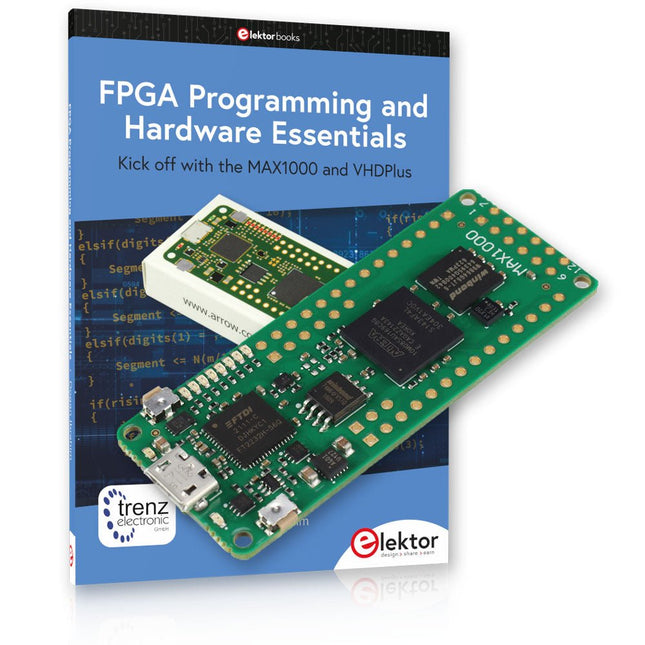
Elektor Bundles MAX1000 FPGA Programming Bundle
Kick off to FPGA Programming with the MAX1000 Board and VHDPlus Ready to master FPGA programming? With this bundle, you'll dive into the world of Field-Programmable Gate Arrays (FPGAs) – a configurable integrated circuit that can be programmed after manufacturing. Bring your ideas to life, from simple projects to complete microcontroller systems! The MAX1000 is a compact and powerful FPGA development board packed with features like memory, user LEDs, push-buttons, and flexible I/O ports. It’s the ideal starting point for anyone wanting to learn about FPGAs and Hardware Description Languages (HDLs). With the enclosed book "FPGA Programming and Hardware Essentials" you'll get hands-on with the VHDPlus programming language – a simpler version of VHDL. You'll work on practical projects using the MAX1000, helping you gain the skills and confidence to unleash your creativity. Projects in the Book Arduino-driven BCD to 7-Segment Display Decoder Use an Arduino Uno R4 to supply BCD data to the decoder, counting from 0 to 9 with a one-second delay Multiplexed 4-Digit Event Counter Create an event counter that displays the total count on a 4-digit display, incrementing with each button press PWM Waveform with Fixed Duty Cycle Generate a PWM waveform at 1 kHz with a fixed duty cycle of 50% Ultrasonic Distance Measurement Measure distances using an ultrasonic sensor, displaying the results on a 4-digit 7-segment LED Electronic Lock Build a simple electronic lock using combinational logic gates with push buttons and an LED output Temperature Sensor Monitor ambient temperature with a TMP36 sensor and display the readings on a 7-segment LED MAX1000 FPGA Development Board The MAX1000 is a customizable IoT/Maker Board ready for evaluation, development and/or use in a product. It is built around the Intel MAX10 FPGA, which is the industry’s first single chip, non-volatile programmable logic device (PLDs) to integrate the optimal set of system components. Users can now leverage the power of tremendous re-configurability paired with a high-performance, low-power FPGA system. Providing internally stored dual images with self-configuration, comprehensive design protection features, integrated ADCs and hardware to implement the Nios II 32-bit microcontroller IP, MAX10 devices are ideal solution for system management, protocol bridging, communication control planes, industrial, automotive and consumer applications. The MAX1000 is equipped with an Arrow USB Programmer2, SDRAM, flash memory, accelerometer sensor and PMOD/Arduino MKR connectors making it a fully featured plug and play solution without any additional costs. Specifications MAX 10 8 kLE - Flash Dual inside - ADC 8x 12 Bit - Temperature Range 0~85°C - Supply USB/pins SDRAM 8 MB 3-axis MEMS LIS3DH USB Programmer on board MEMS Oscillator 12 MHz Switch/LED 2x / 8x Contents of the Bundle Book: FPGA Programming and Hardware Essentials (normal price: €40) MAX1000 FPGA Development Board (normal price: €45) Downloads Software
-

NXP Semiconductors NXP FRDM-MCXN947 Development Board
The FRDM-MCXN947 is a compact and versatile development board designed for rapid prototyping with MCX N94 and N54 microcontrollers. It features industry-standard headers for easy access to the MCU's I/Os, integrated open-standard serial interfaces, external flash memory, and an onboard MCU-Link debugger. Specifications Microcontroller MCX-N947 Dual Arm Cortex-M33 cores @ 150 MHz each with optimized performance efficiency, up to 2 MB dual-bank flash with optional full ECC RAM, External flash Accelerators: Neural Processing Unit, PowerQuad, Smart DMA, etc. Memory Expansion *DNP Micro SD card socket Connectivity Ethernet Phy and connector HS USB-C connectors SPI/I²C/UART connector (PMOD/mikroBUS, DNP) WiFi connector (PMOD/mikroBUS, DNP) CAN-FD transceiver Debug On-board MCU-Link debugger with CMSIS-DAP JTAG/SWD connector Sensor P3T1755 I³C/I²C Temp Sensor, Touch Pad Expansion Options Arduino Header (with FRDM expansion rows) FRDM Header FlexIO/LCD Header SmartDMA/Camera Header Pmod *DNP mikroBUS User Interface RGB user LED, plus Reset, ISP, Wakeup buttons Included 1x FRDM-MCXN947 Development Board 1x USB-C Cable 1x Quick Start Guide Downloads Datasheet Block diagram
-
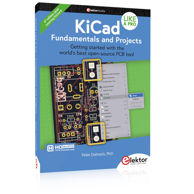
Elektor Publishing KiCad Like A Pro – Fundamentals and Projects
Getting started with the world’s best open-source PCB tool The latest iteration of KiCad, the world’s best free-to-use Printed Circuit Board tool, is packed with features usually found only in expensive commercial CAD tools. This modern, cross-platform application suite built around schematic and design editors, with auxiliary applications is a stable and mature PCB tool. KiCad 8 is a perfect fit for electronic engineers and makers. Here are the most significant improvements and features in KiCad 8, both over and under the hood: Modern user interface, completely redesigned from earlier versions Improved and customizable electrical and design rule checkers Theme editor allowing you to customize KiCad on your screen Ability to import projects from Eagle, CADSTART, and more Python scripting API Improved integrated SPICE circuit simulator Multi-sheet schematics Filters define selectable elements Enhanced interactive router helps you draw single tracks and differential pairs with precision New or enhanced tools to draw tracks, measure distances, tune track lengths, etc. Advanced interactive router Built-in bill of materials generator Realistic ray-tracing capable 3D viewer Customizable teardrops Plug-in manager for quick installation of themes, libraries and functionalities such as autorouters and BOM generators This book will teach you to use KiCad through a practical approach. It will help you become productive quickly and start designing your own boards. Example projects illustrate the basic features of KiCad, even if you have no prior knowledge of PCB design. The author describes the entire workflow from schematic entry to the intricacies of finalizing the files for PCB production and offers sound guidance on the process. Further full-fledged projects, of incremental difficulty, will be presented in a second book, together with a variety of advanced recipes.
-
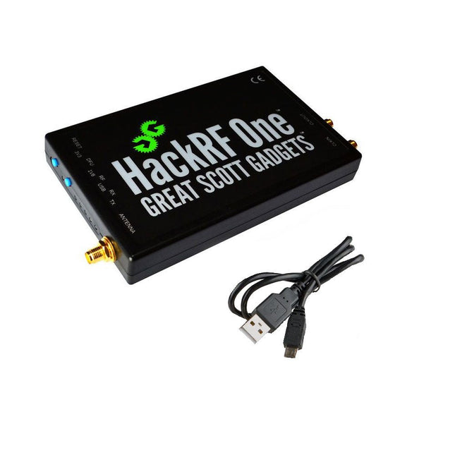
Great Scott Gadgets Great Scott Gadgets HackRF One SDR (1 MHz – 6 GHz)
New Version available! Click here! HackRF One is a Software Defined Radio (SDR) peripheral capable of transmission or reception of radio signals from 1 MHz to 6 GHz. Designed to enable test and development of modern and next generation radio technologies, HackRF One is an open source hardware platform that can be used as a USB peripheral or programmed for stand-alone operation. Specifications 1 MHz to 6 GHz operating frequency Half-duplex transceiver Up to 20 million samples per second 8-bit quadrature samples (8-bit I and 8-bit Q) Compatible with GNU Radio, SDR and more Software-configurable RX and TX gain and baseband filter Software-controlled antenna port power (50 mA at 3.3 V) SMA female antenna connector SMA female clock input and output for synchronization Convenient buttons for programming Internal pin headers for expansion Hi-Speed USB 2.0 USB-powered Open source hardware HackRF One is test equipment for RF systems. It has not been tested for compliance with regulations governing transmission of radio signals. You are responsible for using your HackRF One legally. Included 1x HackRF One SDR 1x Plastic enclosure 1x micro-USB cable Note: An antenna is not included. ANT500 is recommended as a starter antenna for HackRF One. Downloads Documentation GitHub Source code and hardware design files
-
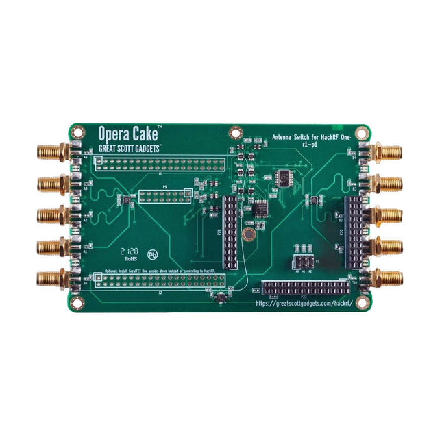
Great Scott Gadgets Great Scott Gadgets Opera Cake (Antenna Switch for HackRF SDR)
Opera Cake is an antenna switching add-on board for HackRF One/Pro that is configured with command-line software either manually, or for automated port switching based on frequency or time. It has two primary ports, each connected to any of eight secondary ports, and is optimized for use as a pair of 1x4 switches or as a single 1x8 switch. Its recommended frequency range is 1 MHz to 4 GHz. When HackRF One/Pro is used to transmit, Opera Cake can automatically route its output to the appropriate transmit antennas, as well as any external filters, amplifiers, etc. No changes are needed to the existing SDR software, but full control from the host is available. Opera Cake also enhances the HackRF One/Pro’s use as a spectrum analyzer across its entire operating frequency range of 1 MHz to 4 GHz. Antenna switching works with the existing hackrf_sweep feature, which can sweep the whole tuning range in less than a second. Automatic switching mid-sweep enables the use of multiple antennas when sweeping a wide frequency range. Downloads Documentation GitHub
-
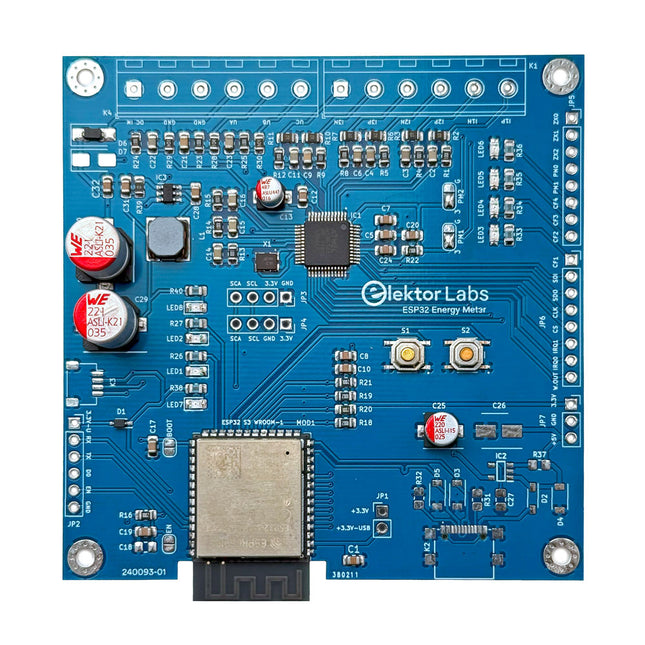
Elektor Labs Elektor ESP32 Energy Meter
The Elektor ESP32 Energy Meter is a device designed for real-time energy monitoring and smart home integration. Powered by the ESP32-S3 microcontroller, it offers robust performance with modular and scalable features. The device uses a 110/230 VAC to 12 VAC step-down transformer for voltage sampling, ensuring galvanic isolation and safety. Its compact PCB layout includes screw-type terminal blocks for secure connections, a Qwiic connector for additional sensors, and a programming header for direct ESP32-S3 configuration. The energy meter is compatible with single-phase and three-phase systems, making it adaptable for various applications. The energy meter is simple to set up and integrates with Home Assistant, offering real-time monitoring, historical analytics, and automation capabilities. It provides accurate measurements of voltage, current, and power, making it a valuable tool for energy management in homes and businesses. Features Comprehensive Energy Monitoring: Get detailed insights into your energy usage for smarter management and cost savings. Customizable Software: Tailor functionality to your needs by programming and integrating custom sensors. Smart Home Ready: Compatible with ESPHome, Home Assistant, and MQTT for full Smart Home integration. Safe & Flexible Design: Operates with a 110/230 VAC to 12 VAC step-down transformer and features a pre-assembled SMD board. Quick Start: Includes one Current Transformer (CT) sensor and access to free setup resources. Specifications Microcontroller ESP32-S3-WROOM-1-N8R2 Energy Metering IC ATM90E32AS Status Indicators 4x LEDs for power consumption indication2x Programmable LEDs for custom status notifications User Input 2x Push buttons for user control Display Output I²C OLED display for real-time power consumption visualization Input Voltage 12~16 VAC (via a step-down transformer 110/230 VAC to 12 VAC) Clamp Current Sensor YHDC SCT013-000 (100 A/50 mA) included Smart Home Integration ESPHome, Home Assistant, and MQTT for seamless connectivity Connectivity Header for programming, Qwiic for sensor expansion Applications Supports single-phase and three-phase energy monitoring systems Dimensions 79.5 x 79.5 mm Included 1x Partly assembled board (SMDs are pre-mounted) 2x Screw terminal block connectors (not mounted) 1x YHDC SCT013-000 current transformer Required Power transformer not included Downloads Datasheet (ESP32-S3-WROOM-1) Datasheet (ATM90E32AS) Datasheet (SCT013-000) Frequently Asked Questions (FAQ) From Prototype to Finished Product What started as an innovative project to create a reliable and user-friendly energy meter using the ESP32-S3 microcontroller has evolved into a robust product. Initially developed as an open-source project, the ESP32 Energy Meter aimed to provide precise energy monitoring, smart home integration and more. Through meticulous hardware and firmware development, the energy meter now stands as a compact, versatile solution for energy management.
-
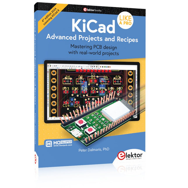
Elektor Publishing KiCad Like A Pro – Advanced Projects and Recipes
Mastering PCB design with real-world projects This book builts on KiCad Like a Pro – Fundamentals and Projects and aims to help you practice your new KiCad skills by challenging you in a series of real-world projects. The projects are supported by a comprehensive set of recipes with detailed instructions on how to achieve a variety of simple and complex tasks. Design the PCBs for a solar power supply, an LED matrix array, an Arduino-powered datalogger, and a custom ESP32 board. Understand the finer details of the interactive router, how to manage KiCad project teams with Git, how to use an autorouter on 2 and 4-layer PCBs, and much more. KiCad 8 is a modern, cross-platform application suite built around schematic and design editors. This stable and mature PCB tool is a perfect fit for electronic engineers and makers. With KiCad 8, you can create PCBs of any complexity and size without the constraints associated with the commercial packages. Here are the most significant improvements and features in KiCad 8, both over and under the hood: Modern user interface, completely redesigned from earlier versions Improved and customizable electrical and design rule checkers Theme editor allowing you to fully customize the look of KiCad on your screen Ability to import projects from Eagle, CADSTART, and more An improved and tightly integrated SPICE circuit simulator Autorouting with the Freerouting plugin Filters define which elements of a layout are selectable Enhanced interactive router helps you draw single tracks and differential pairs with precision New or enhanced tools to draw tracks, measure distances, tune track lengths, etc. Enhanced tool for creating filled zones A customizable coordinate system facilitates data exchange with other CAD applications Realistic ray-tracing capable 3D viewer Differential pair routing Rich repositories of symbol, footprint, and 3D shape libraries Python scripting API for programmatic customization and extensions Improved footprint wizard for fast custom footprints


