
Search results for "raspi OR buffer OR 150719 OR 2"
-
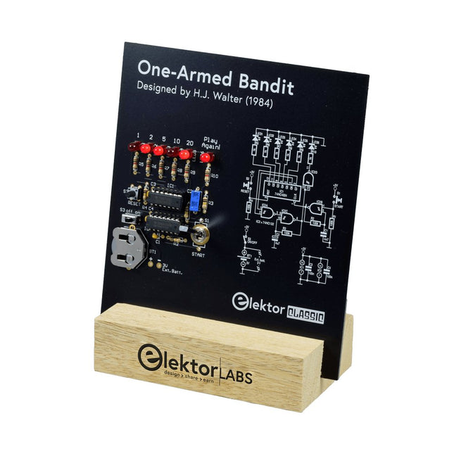
Elektor Labs Elektor One-armed Bandit
Pull Down Lever For Highest Score! This Elektor Circuit Classic from 1984 shows a playful application of CMOS 400x series logic ICs in combination with LEDs, a highly popular combination at the time. The project imitates a spinning-digit type slot machine. The Game To play the game, first agree on the number of rounds. Player 1 actuates the switch lever as long as desired and releases it. The LEDs then show the score which is the sum of the 50-20-10-5 digits lit up. If the Play Again! LED lights, Player 1 has another, “free” round. If not, it’s Player 2’s turn. The players keep tab of their scores, and the highest score wins. Features LEDs Indicate Score Multi-Player and Play Again! Elektor Heritage Circuit Symbols Tried & Tested by Elektor Labs Educational & Geeky Project Through-Hole Parts Only Included Printed Circuit Board All Components Wooden Stand Bill of Materials Resistors (5%, 250 mW) R1,R2,R3,R4 = 100kΩ R5,R6,R7,R8,R9,R10 = 1kΩ Capacitors C1 = 4.7nF, 10%, 50V, 5mm C2 = 4.7μF, 10%, 63V, axial C3,C4 = 100nF, 10 %, 50V, ceramic X7R, 5mm Semiconductors LED1-LED6 = red, 5mm (T1 3/4) IC1 = 74HC4024 IC2 = 74HC132 Miscellaneous S1 = switch, toggle, 21mm lever, SPDT, momentary S2 = switch, tactile, 24V, 50mA, 6x6mm S3 = switch, slide, SPDT IC1,IC2 = IC socket, DIP14 BT1 = PCB-mount CR2032 battery retainer clip Desktop Stand PCB 230098-1 Not included: BT1 = CR2032 coin cell battery
€ 39,95€ 15,98Best Price
-

Elektor Publishing MIT App Inventor for AI and IoT
Build Smart Applications with Raspberry Pi, Arduino, and ESP32 Discover how easy and exciting mobile app development can be with MIT App Inventor. This hands-on guide takes you from basic concepts to building real-world mobile applications using a simple visual programming approach—no prior coding experience required. You will create IoT and AI-powered apps for Android devices and explore how App Inventor can also be used with iPhones and iPads. Connect your applications to platforms such as Arduino UNO R4 WiFi, ESP32, Raspberry Pi Pico (2)W and Raspberry Pi 5, enabling you to build smart, connected systems. Inside the book, you will learn how to: Build interactive apps using buttons, images, sound, and multimedia Create text-to-speech and speech-recognition applications Develop camera-based and location-aware (GPS) apps Design useful tools such as calculators and educational apps Work with smartphone sensors like accelerometers and light sensors Build AI-powered applications, including voice assistants and image-generation features Send and receive messages, and create communication-based apps Connect mobile apps to hardware using Wi-Fi and Bluetooth Control real devices such as LEDs, motors, and sensors Designed for beginners, students, and hobbyists, this book focuses on learning by doing. By the end, you will have the skills and confidence to create your own innovative applications that interact with both the digital and physical worlds. Start building and turning your ideas into reality.
€ 44,95
Members: € 40,46
-

Elektor 01-02/2025 (DE)
Diese Ausgabe steht allen GOLD- und GREEN-Mitgliedern auf der ElektorMagazine-Website zum Download bereit! Sie sind noch kein Mitglied? Hier klicken! DIY-SolarakkusÜber den Selbstbau von Energiespeichern für Solaranlagen Solarmodul-SimulatorFür Test und Optimierung von MPP-Trackern und Invertern Der STM32-Edge-KI-WettbewerbEntdecken Sie den neuen STM32N6 und nehmen Sie am Wettbewerb um 5.000 € teil! Erweiterung der BandlückeWarum gibt es so viel Interesse an SiC und GaN? Power-Bank für NotebooksVerlängern Sie das Leben Ihres alten Laptops! Medizinische RoboterÜberwindung technischer und regulatorischer Hürden Frostwächter für ObstpflanzenMit Temperatur-Datenlogger Das analoge DingDer Arduino des Analog-Computings? Sparsames NetzrelaisMit über 90% Leistungsreduzierung Verbesserung der DC-Last ET5410A+Keep cool and be quiet! electronica 2024 im Rückblick Elektromagnetische VerträglichkeitEMV kurz und bündig! Aller Anfang......muss nicht schwer sein: Aktive Filter Verlustleistung reduzieren mit AbleitkondensatorenEin cleverer Einsatz von kapazitiver Reaktanz Preiswerter 12-Bit-Digital-Analog-Wandler MCP4725Mit EEPROM-Feature für sicheres Einschaltverhalten Fnirsi LCR-ST1, die intelligente LCR-SMD-Pinzette Test- und Messlabor mit Raspberry PiDas Wichtigste zuerst: Der ADC Elektronischer LastwiderstandEin Projekt aus der Kiste 2025: Eine Odyssee in die KIEinige Projekte für das neue Jahr Projekt-Update: Modulares DC-Leistungsmessgerät AmpVolt v2.0100 Ampere und mehr! Projekt 2.0 Ethische Transparenz sichtbar gemachtErgebnisse der Umfrage 2024 von Ethics in Electronics Elektor Audio-DSP FX-Prozessor-BoardTeil 2: Anwendungen erstellen
€ 14,90
-

Arduino Official Arduino USB-C Cable (2-in-1)
Now you can connect your Arduino boards with the official Arduino USB cable. Through a USB-C to USB-C with a USB-A adapter connection, this data USB cable can easily connect your Arduino boards with your chosen programming device. The Arduino USB cable has a nylon braided jacket in the typical Arduino colors white and teal. The connectors have an aluminum shell that protects your cable from harm at the same time as looking cool. Length: 100 cm Aluminium shell with logo Nylon braided jacket white and teal
€ 12,95
Members: € 11,66
-

Elektor Digital Elektor Maart/April 2026 (PDF) NL
Elektor GREEN en GOLD leden kunnen deze uitgave hier downloaden. Nog geen lid? Klik hier om een lidmaatschap af te sluiten. PIO programmeren op de Raspberry Pi PicoNegen instructies, veel mogelijkheden AI buiten de browser brengenAI-CLI's gebruiken voor het coderen, compileren en valideren van embedded projecten De Scrutiny DebuggerDebuggen, visualiseren en testen van code in Embedded C/C++ Sigfox breakout board (1)Een zelfgebouwde radio BoB Low-Noise voeding (2)Constructie, montage en praktische implementatie Eenvoudige signaalgenerator met de RP2040Analoge en digitale signalen voor ongeveer €10 De toekomst van slimme huizen verkennen met Matter en Edge AIBieden de nieuwste updates van Matter en de opkomst van Edge AI technici eindelijk de tools om de intelligente, slimme huizen te bouwen die gebruikers zijn beloofd? Differentiële druksensorenVoorspellend onderhoud in HVAC-systemen Security by designTechnische basisprincipes beperken storingen Embedded security is niet langer optioneel CRA en PQC herzien prioriteiten voor embedded securityWaarom zelfs kleine IoT- en industriële bedrijven een upgradeplan nodig hebben embedded world 2026Een interview met Benedikt Weyerer, Executive Director embedded world Praktijkervaring met I3CGebruik van hardware van ST en Microchip Het BLEnky-projectSnelle prototyping voor Bluetooth Low Energy toepassingen Pulsbreedtemodulatievan een eenvoudige aan/uit-thermostaat naar een rimpelloos DC-signaal AudiotronicaOorstrelende elektronica voor zelfbouw Uit het leven gegrepenRead the f...ing manual! ESP32 audio transceiver board (Deel 4)Afstemmen van de kloksignalen en een bekabelde versie 2026: An AI OdysseyDe kater van Vibe-Coding in 2025 Symmetrische DC-belastingStatische of dynamische en symmetrische gelijkstroombelasting Gezichten tellen met MaixCAMEen eenvoudige methode om de omvang van het publiek vast te leggen
€ 9,95
-

Siglent Siglent SDG2042X 2-ch Arbitrary Waveform Generator (40 MHz)
Siglent's SDG2000X is a series of dual-channel function/arbitrary waveform generators with specifications of up to 120 MHz maximum bandwidth, 1.2 GSa/s sampling rate and 16-bit vertical resolution. The proprietary TrueArb & EasyPulse techniques help to solve the weaknesses inherent in traditional DDS generators when generating arbitrary, square and pulse waveforms. With advantages above, SDG2000X can provide users with a variety of high fidelity and low jitter signals, which can meet the growing requirements of complex and extensive applications. Features Dual-channel, 40 MHz bandwidth, 20Vpp maximum output amplitude, high fidelity output with 80dB dynamic range. High-performance sampling system with 1.2GSa/s sampling rate and 16-bit vertical resolution. No detail in your waveforms will be lost. Innovative TrueArb technology, based on a point-by-point architecture, supports any 8pts~8Mpts Arb waveform with a sampling rate in range of 1μSa/s~75MSa/s. Innovative EasyPulse technology, capable of generating lower jitter Square or Pulse waveforms, brings a wide range and extremely high precision in pulse width and rise/fall times adjustment. Plenty of analog and digital modulation types: AM, DSB-AM, FM, PM, FSK, ASK and PWM. Sweep and Burst functions. High precision Frequency Counter. Standard interfaces: USB Host, USB DeviceUSBTMC, LAN (VXI-11) Optional interface: GPIB. 4.3” touch screen display for easier operation. Specifications Maximum output frequency 40 MHz Output channels 2 Sampling rate 1.2 GSa/s (4X Interpolation) Wave length CH1: 16 Kpts, CH2: 512 Kpts Frequency resolution 1 μHz Vertical resolution 16 bit Standard interfaces Standard interfaces: USB Host, USB Device (USBTMC), LAN (VXI-11) High-performance Sampling System Benefiting from a 1.2GSa/s and 16-bit sampling system, SDG2000X achieves extremely high accuracy performance in both time domain and amplitude, which results in more accurately reconstructed waveforms and lower distortion. Innovative EasyPulse Technology When a Square/Pulse waveform is generated by DDS, there will be a one-clock-jitter if the sampling rate is not an integer-related multiple of the output frequency. SDG2000X EasyPulse technology successfully overcomes this weakness in DDS designs and helps to produce low jitter Square/Pulse waveforms. Innovative TrueArb Technology For arbitrary waveforms, TrueArb not only has all the advantages of traditional DDS, but also eliminates the probability that DDS may cause serious jitter and distortion. Easy controll with 4.3” Touch Screen Display and Arbitrary Waveform Software EasyWave The 4.3” touch screen display, makes operation much more convenient. And EasyWave is a powerful arbitrary waveform editing software that supports several ways to generate arbitrary waveform such as manual drawing, line-drawing, equation-drawing, coordinate-drawing, etc. It is quite convenient for users to edit their own arbitrary waveforms through EasyWave. Included Siglent SDG2042X Arbitrary Function Generator User Manual Guarantee Card CD (including EasyWave 1.0 computer software system) Power Cord USB Cable Quick Start Guide
€ 560,39
-

Elektor Labs Elektor Low-Noise Lab Power Supply
The Elektor Low-Noise Lab Power Supply is a fully analogue, adjustable, medium-power symmetrical bench supply that contains no switching or digital components. It provides an output voltage adjustable between 0 V and ±22 V, and an output current adjustable from 0 A to 1 A. Because it avoids any form of switching circuitry, the design delivers extremely low noise. To display both output voltages and currents, four miniature moving-coil panel meters are used. Most modern laboratory power supplies and AC adapters employ switch-mode techniques. Even the best examples inevitably exhibit high-frequency ripple and other switching artefacts on their output, which can interfere with the testing of sensitive analogue circuits and disturb low-level measurements. To overcome this, the concept here is a completely analogue power supply. Although less efficient than its switch-mode counterparts, the reduced efficiency is of little importance for test-bench use and ensures cleaner, more reliable measurement results. Because many analogue circuits require a symmetrical supply, this design delivers positive and negative output voltages of equal magnitude. A small amount of adjustment is available to compensate for any imbalance. Naturally, a variable current-limit function is also included. The kit includes the components required to build the power supply, except for the transformers. Specifications Output Voltage 0…+22 V, 0, −22 V Output Current 0…+1 A, 0…−1 A Noise −85 dBV, (at 0.95 A/20 V, B = 22 kHz) −84 dBV (at 0.95 A/20 V, B > 500 kHz) Ripple 50 µVRMS (at 950 mA/20 V, B = 22 kHz, mainly 100 Hz component) Included 3x PCBs: Regulator (PCB-1), Mains Filter (PCB-2) and Transformer (PCB-3) All the components except the AC transformers 4x moving-coil meters Additional parts for wiring (wires, banana sockets, IEC Power entry module, etc.) Not included The three AC transformers An enclosure Parts List For the Regulator PCB (240386-1) Resistors (250 mW, 1%) R1 = 12 Ω R2, R8, R37, R62 = 1 MΩ R3, R7, R10, R13, R17, R20, R22, R30, R35, R42, R45, R47, R55, R60 = 100 Ω, 600 mW R4, R5 = 4.7 kΩ R6 = 100 kΩ R9, R12, R14, R36, R38, R39, R61, R63, R66, R72, R78, R79 = 10.0 kΩ, 600 mW R11 = 9.76 kΩ, 600 mW R15, R40 = 44.2 kΩ, 600 mW R16, R41, R77 = 1 kΩ R18, R43 = 1.5 kΩ, 1 W, 5% R19, R44 = 470 Ω, 1 W, 5% R21, R46 = 330 Ω, 600 mW R23, R24, R48, R49 = 1.0 Ω, 1 W R25, R50 = 1 kΩ, 1 W, 5% R26, R28, R51, R53 = 1.000 kΩ 0.1%, 15 ppm/C R27, R29, R52, R54 = 10.00 kΩ 0.1%, 15 ppm/C R31, R56 = 1.2 kΩ, 1 W, 5% R32, R57 = 47 kΩ R33, R58 = 270 Ω R34, R59 = 27 kΩ R64, R69 = 12.0 kΩ R65 = 3.0 kΩ, 600 mW R67, R80 = 470 Ω, 600 mW R68, R70 = 6.8 kΩ, 600 mW R71 = 30.0 kΩ,, 600 mW R73, R74, R75, R76 = 10 MΩ P1, P2, P3 = 10 kΩ, 200 mW, 20%, potentiometer, 1 turns, single, lin., panel mount P4, P5 = 500 Ω, 500 mW, 10%, trimmer, 25 turns, 3296Y-1-501LF Bourns P6, P7 = 10 kΩ, 500 mW, 10%, trimmer, 25 turns, 3296Y-1-501LF Bourns Capacitors C1 = 100 nF, 50 V, 10%, ceramic X7R, LS 5 mm C2, C3, C6, C7, C30 = 10 µF, 63V, 20%, LS 2.5 mm, 3000hours@105°C C4, C5, C8, C9, C13, C14, C18, C19, C23, C24, C28, C29, C31, C32, C38, C39 = 100 nF, 250 V, 10%, PET, LS 7.5 mm C10, C20 = 47 nF, 100 V, 5%, PET, LS 5 mm C11, C21 = 10 nF, 100 V, 5%, PET, LS 5 mm C12, C22 = 220 µF, 35 V, 20%, 0.024 Ω, LS2.5/3.5 mm, Ir 3.4 A, 2000hours@125°C, polymer C15, C25 = 120 µF, 50 V, 20%, ESR 0.02 Ω, Diam. 10 mm max., LS 5 mm C16, C26 = 15 nF, 100 V, 5%, PET, LS 5 mm C17, C27 = 47 nF, 100 V, 5%, PET, LS 5 mm C33, C34 = 22 µF, 50 V, 20%, LS 2 mm, 10000 hours @ 105°C C35, C36, C44, C45 = 1 µF, 100 V, 10%, LS 5 mm, ceramic X7R C37 = 100 uF, 50 V, 20%. LS 3.5 mm C40, C41, C42, C43, C46, C47, C48, C49 = 1000 µF, 50 V, 20%, LS 5/7.5 mm, Ir 3.32 A, 10000hours@105°C, D 16 mm C50, C51, C52, C53 = 47 nF, 100 V, 10%, ceramic X7R, LS 5 mm Inductors L1, L2 = 4.7 µH, 3.2 A, 0.033 Ω, LS 5 mm, RLB0914-4R7ML Bourns L3 = Commom mode choke, 14.5 mH, 3 A, SSRH24NH-30145 Kemet Semiconductors D1, D2, D3, D4, D5, D9, D10, D11, D15 = BAT85, DO-34 D6, D7, D12, D13 = SR560, DO-201AD D8, D14, D16 = 1N4148, DO-35 D17 = Zenerdiode, 5.6 V, 0.5 W, DO-41 D18, D19 = 1N4004, DO-41 D20, D21 D22, D23 = V30100CI-M3/P, dual common cathode, TO-220 D24 = Zener diode, 30 V, 1 W, DO-41 LED1, LED2 = LED, red, T-1 (3 mm) LED3, LED4 = LED, green, T-1 (3 mm) TVS1, TVS2 = BZW50-33B, R6 T1, T2, T4 = BC337.25, TO-92 T3 = NJW0302G, TO-3P T5, T6, T8 = BC327.25, TO-92 T7 = NJW0281G, TO-3P T9 = BD139, TO-126 (SOT-32) IC1 = LM334Z, TO-92 IC2 = LM4040AIZ-5.0/NOPB, TO-92 (TO-226AA-3) IC3, IC4 = OPA2992IDR, SOIC-8 IC5, IC6 = OPA4992IDR, SOIC-14 IC7 = OPA992IDBVR, SOT-23-5 IC8 = LM339N, DIP-14 IC9 = LM317, TO-220 IC10 = LM337, TO-220 Others F1, F2 = 5×20 mm fuse, 1.6 A, fast acting HS1, HS2 = Heatsink MC33271 (for T3/T7), 2.7°C/W, PCB mount, height 63.5 mm K1, K4 = 3-way screw terminal block, LS 3.5 mm, max. 1.5 mm² K2, K3 = 3-way screw terminal block, LS 3.5 mm, max. 1 mm² M1, M3 = Moving coil meter, Range 30 V, type 91C4, 45×45 mm M2, M4 = Moving coil meter, Range 1 A, type 91C4, 45×45 mm² RE1 = Relay DPDT,5V, UA2-5NU Miscellaneous 3× 3-way screw terminal block, LS 3.5 mm, max. 1 mm² (for P1, P2, P3) 4× Pin header, 1×2, vertical, pitch 2.54 mm (for LED1, LED2, LED3, LED4) 4× Pin socket, 1×2, vertical. pitch 2.54 mm (for LED1, LED2, LED3, LED4) 2× Heatsink FK222SA220, 20°C/W, PCB mount (for IC9 & IC10) 2× Mica thermal pad for TO-220, 12×18×0.05 mm (for IC9 & IC10) 2× Insulating bushing IB 6, TO-220 (for IC9 & IC10) 2× Ceramic thermal pad, 23×20×2 mm (for T3 & T7) 2× PCB Fuse Holder, for 5×20 mm fuse, 10 A (for F1, F2) 2× Cover for PCB Fuse Holder, transparent (for F1, F2) 2× 2-way screw terminal block, LS 3.5 mm, max. 1 mm² (for M1 & M3) 2× 2-way screw terminal block, LS 3.5 mm, max. 1.5 mm² (for M2 & M4) 8× M3 solder lug, thickness 0.35 mm (for M1…M4) M4 solder lug, thickness 0.35 mm (to connect 4 mm banana connectors) Screened cable, 1 pair, 2×24 AWG/0.22 mm², 1 m (for P1, P2 & P3) IC socket, DIP, 14 contacts (for IC8) M3 washer, plain, steel M3 screw, 16 mm, steel, pan head M3 nut M3 spring washer 50 mm M3 standoff, steel, male-female 12 mm M3 standoff, steel, male-female 10 mm M3 standoff, steel, male-female M3 screw, 8 mm, steel, pan head For the Mains Fiter PCB (240386-2) Resistor R1 = 220 kΩ, 1 W, 500 V, 5% Capacitors C1, C2 = 470 nF, 305 VAC, Class X2, 11 × 27 mm max., LS 15/22.5 mm C3, C4, C5, C6 = 2.2 nF, 300 VAC, Class Y2, 13 × 4 mm, LS 10 mm, PP Inductors L1, L2 = Common-mode choke, 6.8 mH, 1.7 A, TDK B82732R2172B030 Semiconductor MOV1 = TVS varistor, 300 VAC, S14K300 (230 VAC, B72214S0301K101) and SK14K150 (150 VAC, B72214S0151K101) Others K1, K2 = 3-way screw terminal block, LS 7.62 mm F1 = Time-delay fuse, 0.5 A (230 VAC) or 1 A (115 VAC) Miscellaneous 1× Fuse holder, 5×20 mm, 10 A, 500 VAC 1× Transparent fuse cover 4× 10 mm M3 standoff, steel, male–female 4× M3 screw, 8 mm, steel, pan head 4× M3 nut For the Transformer PCB (240386-3) Resistors R1, R2 = 2.7 kΩ, 600 mW, 1% R3 = 10.0 kΩ, 600 mW, 1% Capacitor C1 = 220 µF, 50 V, 20%, Ø10 mm, LS 5 mm, 4000 h @ 105°C Transformers (not included in this kit!) TR1, TR2, TR3 = 2×7 V, 25 VA, PCB-mounted toroid, 70060K Talema Semiconductors D1–D4 = 1N4148, DO-35 D5, D6 = 1N4004, DO-41 D7 = Zener 5.6 V, 1.3 W, DO-41 LED1 = LED, red, T-1 (3 mm) IC1, IC2 = MOC8021M, CTR ≥ 1000%, DIP-6 Others F1, F2, F3 = 160 mA time-delay fuse (230 VAC) or 315 mA time-delay fuse (115 VAC) K1 = 2-way screw terminal block, LS 7.62 mm K2 = 3-way screw terminal block, LS 3.5 mm, max 1.5 mm² K3, K4 = 3-way screw terminal block, LS 3.5 mm, max 1 mm² RE1, RE2 = Relay DPDT, 5 A/250 VAC / 24 VDC Miscellaneaous 1× Pin header 1×2, pitch 2.54 mm + matching socket for LED1 3× Fuse holder 5 × 20 mm, 10 A, 500 VAC + transparent cover 3× M4 screw, 8 mm, pan head + washer for TR1-TR3 8× M3 screw, 8 mm, pan head + nut + washer 8× 10 mm M3 standoff, steel, male–female 2× IC socket, DIP-6 for IC1 & IC2 Additional Parts 1 m red insulated wire, stranded, 1.5 mm² 0.5 m blue insulated wire, stranded, 1.5 mm² 0.5 m black insulated wire, stranded, 1.5 mm², 0.5 m 2 m red insulated wire, stranded, D 0.56 mm (0.25 mm²) 2 m black insulated wire, stranded, D 0.56 mm (0.25 mm²) 0.5 m Multicore Cable, Flexible, 3 Core, 0.75 mm² (24 x 0.2 mm) Red banana socket Black banana socket Blue banana socket Green banana socket IEC Power Entry Module with switch, IEC C14 3 crimp terminals, FASTON, 4.75 x 0.81 mm 3 knobs Links Elektor Labs JumpStarter Page Article (Part 1) Article (Part 2)
€ 299,00€ 249,00Best Price
-
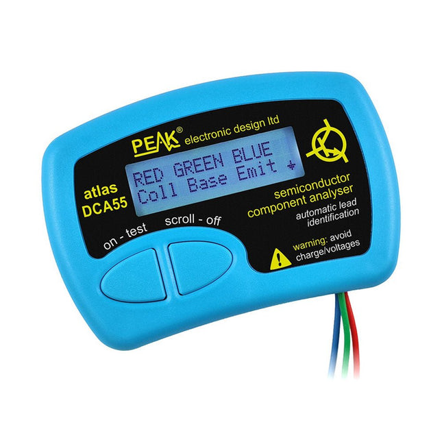
Peak Peak Atlas DCA55 Semiconductor Analyzer
The Peak Atlas DCA55 is great for automatically identifying the type of semiconductor on the test leads as well as the pinout and many other parameters. Supports transistors MOSFETs, JFETs (gate pin only can be identified), diodes, LEDs and lots more. Automatically identifies type of component, pinout and other important parameters. Now features transistor leakage measurement and Germanium/Silicon identification. Component Support Bipolar transistors (NPN/PNP inc Silicon/Germanium) Darlington transistors (NPN/PNP) Enhancement mode MOSFETs (N-Ch and P-Ch) Depletion mode MOSFETs (N-Ch and P-Ch) Junction FETs (N-Ch and P-Ch). Only gate lead identified Diodes and diode networks (2 and 3 lead types) LEDs and bi-colour LEDs (2 lead and 3 lead types) Low power sensitive Triacs and Thyristors (<5 mA trigger and hold) Measurements Part type identification Pinout identification BJT current gain (hFE) BJT base emitter voltage (Vbe) BJT collector leakage current MOSFET gate threshold voltage Diode forward voltage drop (Vf) Specifications Analyzer type Transistors, Diodes, LEDs, MOSFETs, JFETs Pinout detection Full pinout (only Gate on JFETs) Pinout configuration Connect any way round Transistor measurements Vbe, hFE, Iceo MOSFET measurements Vgs(on) Diode measurements Vf Probe type Universal grabber type Battery Single AAA cell (supplied). Life typically 1300 ops Test conditions Typically 5 mA, 5 V peak Display type Alphanumeric LCD (with backlight) Included Peak Atlas DCA55 Semiconductor Analyzer Comprehensive illustrated user guide Fitted universal hook probes AAA Alkaline battery Downloads Datasheet (EN) User Guide (EN) User Guide (IT)
€ 83,49
-
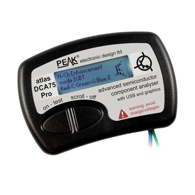
Peak Peak Atlas DCA75 Pro (Advanced Semiconductor Analyzer)
The DCA75 Pro is a great instrument that combines ease-of-use with amazing features. It can automatically identify a huge range of semiconductors, automatically identify pinouts and measure detailed parameters. Features Built-in graphics display (now backlit) to show detailed schematic of the component you're testing as well as pinout and measurement data USB connectivity to allow curve tracing, data storage/retrieval and device matching on your Windows PC (Windows 7 and higher) Single internal AAA alkaline cell for standalone operation Component Support Bipolar transistors (NPN/PNP inc Silicon/Germanium) Darlington transistors (NPN/PNP) Enhancement mode MOSFETs (N-Ch and P-Ch) Depletion mode MOSFETs (N-Ch and P-Ch) Junction FETs (N-Ch and P-Ch). Both symmetrical and asymmetrical types Enhancement IGBTs (N-Ch and P-Ch) Diodes and diode networks (2 and 3 lead types) Zener diodes (up to about 9 V) Voltage regulators (up to about 8 V) LEDs and bi-colour LEDs (2 lead and 3 lead types) Low power sensitive Triacs and Thyristors (<10 mA trigger and hold) Measurements BJT current gain (hFE) BJT base emitter voltage (Vbe) BJT collector leakage current MOSFET on and off gate threshold voltages MOSFET transconductance JFET pinch-off voltage JFET transconductance JFET IDSS (drain current for Vgs=0) IGBT on and off gate threshold voltages IGBT transconductance Voltage regulator output voltage Voltage regulator quiescent current consumption Voltage regulator drop-out voltage Zener voltage Diode forward voltage drop Specifications Analyzer type Semiconductor components Component detection Automatic Pinout detection Automatic, connect any way round Display type Graphic LCD (now backlit) Interface type USB for optional PC connection PC functions Curve tracing (Windows 7 and higher) Software Included on USB drive for Windows 7 and higher Battery Single AAA cell (supplied) Included Peak Atlas DCA75 Pro PC software on a USB Flash Drive for Windows 11, 10, 8, 7, XP Micro USB cable Fitted universal premium hook probes AAA Alkaline battery Downloads Datasheet (EN) User Guide (EN) User Guide (IT) Software Installation Guide (EN) Software and Firmware Package
€ 192,39
-

Elektor Digital Elektor 09-10/2021 (PDF)
DIE NEURONEN IN NEURONALEN NETZWERKEN VERSTEHENTeil 1. Künstliche Neuronen EMV-VOR-KONFORMITÄTSTESTER FÜR IHR PROJEKT MIT DC-VERSORGUNGTeil 1: Was ist eine Netznachbildung? ELEKTRONISCHE LAST FÜR DC UND ACBis zu 400 V und 10 A ALLER ANFANG …ist gar nicht schwer! NVIDIA JETSON NANO - BILDVERARBEITUNG FÜR EINSTEIGERTeil 1: Hard- und Software im Überblick NETZTRANSFORMATOREN AUS DER NÄHE BETRACHTETWie verhalten sie sich beim Ein- und Ausschalten? PICAN 3 - YES WE CAN!CAN-Zusatzboard für Raspberry Pi 4 BALKONKRAFTWERKSelbst installiert = schnell amortisiert! FOTOGRAFIEREN UND VIDEO-STREAMING MIT DEM RASPBERRY PI 4Die High-Quality-Kamera des Raspberry Pi in der Praxis VERWENDUNG VON DISPLAYS IN RASPBERRY-PI-PROJEKTENBeispiel-Kapitel: Organische Leuchtdioden-Displays (OLED) PARALLAX PROPELLER 2Teil 4: Senden von Strings 60 JAHRE ELEKTOR: SEPTEMBER-RENAISSANCEDer Plan, der Plan, ein leerer Wahn ... ZUTRITT FÜR UNBEFUGE VERBOTEN ERWÜNSCHTIn Friesland, wo die Röhren blühen ... HYBRIDE SCHALTUNGENBemerkenswerte Bauteile KOMPASSROSE MIT DEM GY-271Oder, warum man mit dem Handy Achten gehen muss… KENNEN SIE IHREN FUSSABDRUCKBerechnen Sie die CO2-Bilanz Ihrer Elektronik ESP32-VERBUNDENES THERMOSTATLagern Sie Ihren Wein bei der richtigen Temperatur! MAGNETISCHE LEVITATION DIE DIGITALE ARTEin ESP32 Pico ersetzt den analogen Komparator ULTIMATE ARDUINO UNO HARDWARE MANUALEin beispielhaftes Kapitel: Bootloader für den Haupt-Mikrocontroller MICROPYTHON FÜR DEN ESP32 UND CO.Teil 2. Matrix-Displays einfach ansteuern MADMACHINE SWIFTIO-KARTEModerne Sprache trifft moderne Hardware AUS DEM LEBEN GEGRIFFENEine elektronische On/Off-Beziehung HEXADOKUSudoku für Elektroniker
€ 11,90
-

Elektor Classics The Ton Giesberts Collection (USB Stick)
Practical Projects in Analog, Audio and Beyond Discover a remarkable collection of more than 450 electronics projects published in Elektor Magazine and carefully selected by renowned Elektor Lab engineer Ton Giesberts. The USB drive brings together a wide variety of circuits, designs, and practical project ideas created by numerous Elektor authors and engineers over the years. Covering a broad range of electronics topics, this extensive archive is a valuable source of knowledge and inspiration for engineers, makers, students, and electronics enthusiasts. More than 450 selected Elektor projects Carefully compiled by Elektor engineer Ton Giesberts Ideal for building, experimenting, and discovering new ideas Explore decades of Elektor expertise in one comprehensive project collection. Highlights Q-Watt Audio Power Fortissimo-100 High-End Amplifier Buffer Board for the Raspberry Pi 400 USB-to-Multi-Protocol Serial Converter DDS Function Generator AC/DC Power Meter Charge-a-Phone Specifications Storage 8 GB Connectors 1x USB-A1x USB-C System requirements PC with Adobe Reader 7.0 or higher Web browser
€ 49,95€ 39,95Best Price
-

Elektor Digital MIT App Inventor for AI and IoT (E-book)
Build Smart Applications with Raspberry Pi, Arduino, and ESP32 Discover how easy and exciting mobile app development can be with MIT App Inventor. This hands-on guide takes you from basic concepts to building real-world mobile applications using a simple visual programming approach—no prior coding experience required. You will create IoT and AI-powered apps for Android devices and explore how App Inventor can also be used with iPhones and iPads. Connect your applications to platforms such as Arduino UNO R4 WiFi, ESP32, Raspberry Pi Pico (2)W and Raspberry Pi 5, enabling you to build smart, connected systems. Inside the book, you will learn how to: Build interactive apps using buttons, images, sound, and multimedia Create text-to-speech and speech-recognition applications Develop camera-based and location-aware (GPS) apps Design useful tools such as calculators and educational apps Work with smartphone sensors like accelerometers and light sensors Build AI-powered applications, including voice assistants and image-generation features Send and receive messages, and create communication-based apps Connect mobile apps to hardware using Wi-Fi and Bluetooth Control real devices such as LEDs, motors, and sensors Designed for beginners, students, and hobbyists, this book focuses on learning by doing. By the end, you will have the skills and confidence to create your own innovative applications that interact with both the digital and physical worlds. Start building and turning your ideas into reality.
€ 34,95
Members: € 31,46


