Zelfbouw versterkers en luidsprekers
Deze speciale uitgave staat vol met interessante bouwbeschrijvingen en achtergrondartikelen van internationaal gerenommeerde ontwerpers. Het gaat in alle gevallen om nieuwe, nog niet eerder gepubliceerde artikelen.
Inhoudsopgave
Buizenversterkers
30 Watt buizenversterker met variabele dempingsfactor
50 Watt super triode versterker
300 Watt buizen eindversterker
Digibias: digitaal de ruststroom instellen en bewaken
Luidsprekers
Paper Hatt - klein maar fijn
Origami M en C – compacte actieve subwoofer in twee smaken
Meerweg open baffle systemen – basistheorie, ontwerp en meetmethode
Moai – hightech uit Scandinavië
OB3W – drieweg open-baffle dipool van formaat
1685a – compacte tweeweg vloerstaander
ScanSpeak Vertigo – duizelingwekkend mooi driewegsysteem
Halfgeleiderversterkers
MinimA – minimalistische 120W klasse-B versterker
Gebalanceerde voorversterker met actief wisselfilter
RelaiXed – gebalanceerde voorversterker met relais
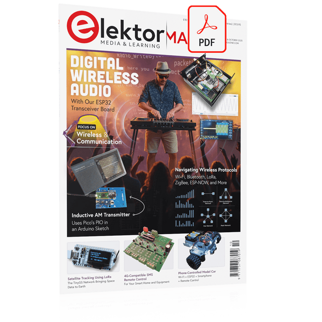
Elektor GREEN and GOLD members can download their digital edition here.
Not a member yet? Click here.
ESP32 Audio Transceiver Board (Part 2)Wireless Audio Transmission
Inductive AM TransmitterUses Pico’s PIO in an Arduino Sketch
Navigating Wireless ProtocolsA Technical Guide
Satellite Tracking Using LoRaThe TinyGS Network Bringing Space Data to Earth
4G-Compatible SMS Remote ControlRemotely Control Your Equipment
High-Speed ProbeHigh-Impedance Inputs for Signals up to 200 MHz
From Life’s ExperienceKafka
KrakenSDR
Performance Tests with the RP2350Is an Upgrade from Raspberry Pi Pico 1 to Pico 2 Worthwhile?
Contact-Free E-Field Measurements (2)A Laser Vibrometer for Assessing the Membrane's Vibrations
Crystals and OscillatorsImproving Crystal Accuracy Through Capacitor Selection
Starting Out in ElectronicsSpecial Audio ICs
Getting Started with Coding a DIY Project
SPECTRAN® V6 MobileModular, Configurable Real-Time Spectrum Analyzer for Reliable Measurements Across All Frequency Ranges
The Future of AI Is Forged in SiliconAn Interview with Anastasiia Nosova
Autonomous Sensor Node v2.0 (System Architecture)Solar-Powered Sensing Platform with Integrated GPS, LoRaWAN, and More
Precise PositioningBluetooth Channel Sounding Tested
Powering the Future of Wireless CommunicationBTRY’s Ultra-Thin Solid-State Batteries
Test-Driven Development in Firmware Writing
Phone-Controlled Model CarWi-Fi + ESP32 + Smartphone = Remote Control
2025: An AI OdysseyAI Reasoning Models: The Chain-of-Thought Revolution
Solar Charge Controller with MPP Tracking (3)Software and Commissioning
Raspberry Pi Zero Web Streaming CameraUsing the ZeroTier VPN
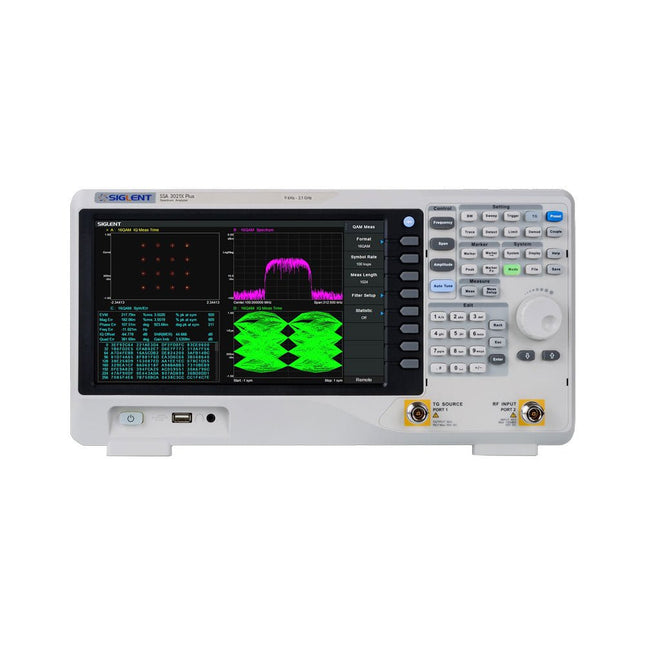
The Siglent SSA3021X Plus spectrum analyzer is a powerful and flexible tool for RF signal and network analysis. With a frequency range of 2.1 GHz, the analyzer delivers reliable automatic measurements and multiple modes of operation: spectrum analyzer the base, optional functions include RF power measurement, vector signal modulation analysis, reflection measurement, and EMI test.
Applications include broadcast monitoring/evaluation, site surveying, S-parameter measurement, analog/digital modulation analysis, EMI pre-compliance test, research and development, education, production, and maintenance.
Features
Spectrum Analyzer Frequency Range from 9 kHz to 2.1 GHz
–161 dBm/Hz Displayed Average Noise Level (Typ.)
–98 dBc/Hz. @ 10 kHz Offset Phase Noise (1 GHz, Typ.)
Level Measurement Uncertainty <0.7 dB (Typ.)
1 Hz Minimum Resolution Bandwidth (RBW)
Preamplifier (Std.)
Tracking Generator (incl. free of charge)
Analog and Digital Signal Modulation Analysis Mode (opt.)
Reflection Measurement Kit (opt.)
EMI Filter and Quasi-Peak Detector Kit (opt.)
Advanced Measurement Kit (opt.)
10.1-inch Multi-Touch Screen , Mouse and Keyboard supported
Web Browser Remote Control on PC and Mobile Terminals and File Operation
Specifications
SSA3015X Plus
SSA3021X Plus
SSA3032X Plus
SSA3075X Plus
Frequency Range
9 kHz ~ 1.5 GHz
9 kHz ~ 2.1 GHz
9 kHz ~ 3.2 GHz
9 kHz ~ 7.5 GHz
Resolution Bandwidth
1 Hz ~ 1 MHz
1 Hz ~ 1 MHz
1 Hz ~ 1 MHz
1 Hz ~ 3 MHz
Phase Noise
<–99 dBc/Hz
<–98 dBc/Hz
<–98 dBc/Hz
<–98 dBc/Hz
Total Amplitude Accuracy
<1.2 dB
<0.7 dB
<0.7 dB
<0.7 dB
Display Average Noise Level
–156 dBm/Hz
–161 dBm/Hz
–161 dBm/Hz
–165 dBm/Hz
Included
Siglent SSA3021X Plus spectrum analyzer
USB cable
Power cord
Quick start guide
Downloads
Datasheet
Manual
Documentation
Firmware
Le téléchargement intégral de ce numéro est disponible pour nos membres GOLD et GREEN sur le site Elektor Magazine !
Pas encore membre ? Cliquez ici.
carte émetteur-récepteur audio ESP32 (2)Transmission audio sans fil
émetteur AM par inductionUtiliser les PIO du Pico dans un croquis Arduino
les protocoles sans filUn guide technique
suivi de satellites avec LoRaTinyGS, le réseau open source qui capte les données spatiales
télécommande par sms compatible 4GContrôlez votre équipement à distance
sonde haute vitesseMesure à haute impédance jusqu’à 200 MHz
sur le vifKafka
KrakenSDR
tests de performance avec le RP2350Pico 2 : une vraie amélioration ?
mesures de champ électrique sans contact (2)Un vibromètre laser pour l’analyse des vibrations de la membrane
quartz et oscillateursAméliorer la précision des quartz grâce au choix des condensateurs
démarrer en électroniqueCI audio originaux
se lancer dans le codage d'un projet DIY
SPECTRAN® V6 MobileAnalyseur de spectre temps réel modulaire et configurable pour des mesures fiables sur l’ensemble des plages de fréquences
l’avenir de l’IA repose sur le siliciumEntretien avec Anastasiia Nosova
nœud de capteurs autonome v2.0 (architecture du système)Plateforme de mesure autonome alimentée par énergie solaire, avec GPS intégré, LoRaWAN et plus encore
positionnement précisTests du sondage de canal Bluetooth
développement logiciel piloté par les tests
voiture miniature contrôlée par SmartphoneWi-Fi + ESP32 + Smartphone = contrôle à distance
2025 : une odyssée de l’IAModèles de raisonnement en IA : la révolution de la chaîne de pensée
contrôleur de charge solaire avec MPPT (3)Logiciel et mise en service
caméra Web Raspberry Pi ZeroStreaming avec VPN ZeroTier
Diese Ausgabe steht allen GOLD- und GREEN-Mitgliedern auf der ElektorMagazine-Website zum Download bereit!
Sie sind noch kein Mitglied? Hier klicken!
MultiRF-EntwicklungsboardEine Plattform zur Evaluierung drahtloser Protokolle für kurze und lange Reichweiten
Elektor wird 65Elektronik im Wandel seit 1961
WLAN-basierte Personenerkennung mit dem ESP32Wenn der Router zum Bewegungsmelder wird
Drahtlose WaagenVier kleine Waagen = eine große Waage
Walter, das kompakte IoT-ModulESP32-S3-SoC, LTE-M/NB-IoT-5G-Modem und GNSS-Receiver
3- und 4-Draht-RTD-Sensoren konditionierenMit Vollbereichsabgleich und Kabelkompensation
Drei in einem: 2-Kanal-Oszilloskop/Generator/MultimeterEin Test des Fnirsi 2D15P
electronica Fast Forward 2026 für Start-ups und Industriepartner
EcologgingEine modulare IoT-Messstation für Umweltdaten
Drahtlos-Anbindung für MedizingeräteImmer am Puls mit Bluetooth LE
AudiotronicsBrummunterdrückung
Mehr Effizienz in der Landwirtschaft durch KI-Modelle und SensorenSteigerung der landwirtschaftlichen Produktivität
OPC UA – ein ÜberblickPlattformunabhängiger Datenaustausch
Redox-Meter
Instrumentenverstärker für Physik- und Engineering-Experimente
Aktive differentielle Audio-FilterFür professionelle Frequenzweichen und mehr
Elektor-Community-Tipps zu IoT und Sensoren
Telegram-gesteuerter WarmwasserbereiterEine Lösung mit ESP32 und Arduino-Software
2026: Eine KI-OdysseeWas wurde eigentlich aus der Fuzzy-Logik?
Projekt 2.0
Alarmsignalinjektor + PowerTools zum Suchen verdeckt verlegter Leitungen
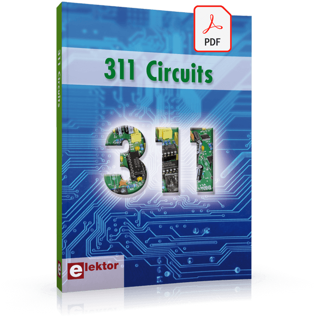
311 Circuits is the twelfth book in Elektor’s celebrated ‘300’ series. An immense source of inspiration for all electronics enthusiasts and professionals, this book deserves a place not far from the workbench.
This book contains circuits, design ideas, tips and tricks from all areas of electronics: audio & video, computers & microcontrollers, radio, hobby & modelling, home & garden, power supplies & batteries, test & measurement, software, not forgetting a section ‘miscellaneous’ for everything that doesn’t fit in one of the other categories.
311 Circuits presents complete solutions for numerous problems, as well as starting points for your own creations. 311 Circuits has been compiled from the 2009, 2010 and 2011 ‘Summer Circuits’ double editions of Elektor magazine. The book is mostly based on readers’ contributions, supplemented by circuits engineered and developed in the Elektor Labs.
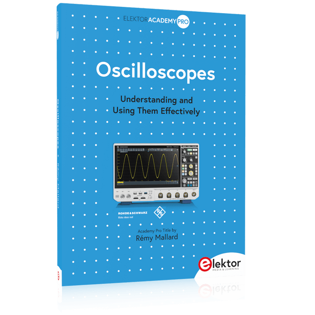
Understanding and Using Them Effectively
What happens in electronics is invisible to the naked eye. The instrument that allows to accurately visualize electrical signals, the one through which the effects of electronics become apparent to us, is the oscilloscope.
Alas, when one first ventures into electronics, it is often without an oscilloscope. And one is left fumbling, both physically and mentally. Observing an electrical signal on a screen for the first time is a revelation. Nobody wishes to forgo that marvel again. There is no turning back.
In electronics, if one wishes to progress with both enjoyment and understanding, an oscilloscope is essential. This marks the beginning of a period of questioning: how to choose one? And no sooner is that question answered than a whole string of others arises, which can be summed up in just one: how does one use the oscilloscope in such a way that what it displays truly reflects the reality of the signals?
Rémy Mallard is a passionate communicator with a gift for making complex technical subjects understandable and engaging. In this book, he provides clear answers to essential questions about using an oscilloscope and offers a wealth of guidance to help readers explore and understand the electrical signals behind electronic systems. With his accessible style and practical insights, this book is a valuable tool for anyone eager to deepen their understanding of electronics.
Make your project dreams come true: an odometer for the hamster wheel, a fully automatic control of your ant farm with web interface, or the Sandwich-O-Mat – a machine that toasts and grills sandwiches of your choice.
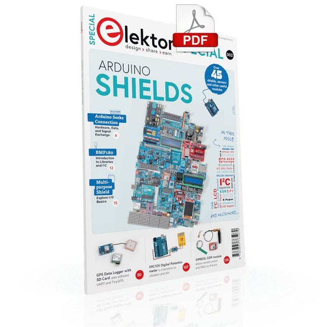
With the Arduino and the DIY or Maker movement, not only did entry into microcontroller programming become child's play, but a second development also took place: Resourceful developers brought small boards – so-called shields or modules – to the market, which greatly simplified the use of additional hardware. The small modules contain all the important electronic parts to be connected to the microcontroller with a few plug-in cables, eliminating the need for a fiddly and time-consuming assembly on the plug-in board. In addition, it is also possible to handle tiny components that do not have any connecting legs (so-called SMDs).
Projects Discussed
Arduino seeks connection
BMP and introduction to libraries, I²C
Learn I/O basics with the multi-purpose shield
I²C LCD adapter and DOT matrix displays
LCD keypad shield
Level converter
W5100: Internet connection
I/O expansion shield
Relays and solid-state relays
The multi-function shield: A universal control unit
Connecting an SD card reader via SPI
Keys and 7-segment displays
16-bit ADC
MCP4725 DAC
16-way PWM servo driver
MP3 player
GPS data logger using an SD card
Touch sensor
Joystick
SHT31: Temperature and humidity
VEML6070 UV-A sensor
VL53L0X time-of-flight
Ultrasonic distance meter
MAX7219-based LED DOT matrix display
DS3231 RTC
Port expander MCP23017
433 MHz radio
MPU-650 gyroscope
ADXL345 accelerometer
WS2812 RGB LEDs
Power supply
MQ-xx gas sensors
CO2 gas sensor
ACS712 current sensor
INA219 current sensor
L298 motor driver
MFRC522 RFID
28BYJ-48 stepper motor
TMC2209 silent step stick
X9C10x digital potentiometer
ST7735 in a color TFT display
e-Paper display
Bluetooth
Geiger counter
SIM800L GSM module
I²C multiplexer
Controller Area Network
The Most Iconic Oscilloscopes in Electronics History
The 7000 Series was the most iconic family of oscilloscopes in the history of technology. Introduced in 1969 by Tektronix, the sector’s leader at the time, this remarkable line of instruments defined an era and became a benchmark for generations of engineers, researchers, and technicians.
Throughout the 1970s and well beyond, 7000-Series oscilloscopes were a constant presence in laboratories, universities, and industrial facilities around the world. Their modular plug-in architecture, exceptional flexibility, and outstanding performance embodied the engineering philosophy that made Tektronix synonymous with accuracy, innovation, and reliability.
This book offers an in-depth exploration of the 7000-Series oscilloscopes, combining historical context, technical analysis, and practical insight into their design and restoration. Conceived as a continuation of Tektronix Epic Oscilloscopes, this work expands the subject into two volumes: the first devoted to mainframes and core technologies, the second focused entirely on plug-ins.
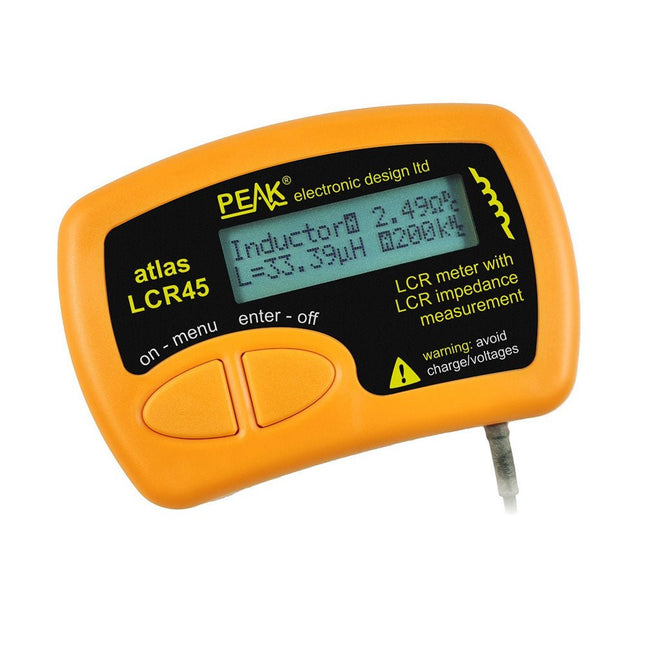
The Peak Atlas LCR45 does everything that the popular LCR40 does, but it has some significant enhancements. The LCR45 features a new high capacity micro and high resolution ADCs.
LCR45 incorporates advanced maths, based on Complex Impedance analysis. This allows for enhanced component value measurement as well as a comprehensive and detailed impedance display.
Features
Supplied with gold plated removable hook probes
Fluid measurements with hold function
Automatic or manual component type
Automatic or manual test frequency, DC, 1 kHz, 15 kHz or 200 kHz
Enhanced measurement resolution: 0.2 µH, 0.2 pF and 0.2 Ohms
Easy menu system for user settings
Enhanced compensation for component parasitics and losses (such as core losses etc)
Automatic or manual power-off
Specifications
Analyser type
LCR and component impedance
Component types
Auto/Manual for L,C & R
Measurement types
Inductance, Capacitance and Resistance
Other measurements
Complex impedance/admittance
More measurements
Magnitude and Phase of impedance
Inductance range
0uH to 2H
Capacitance range
0 pF to 10000 uF
Resistance range
0R to 2MR
Test frequency
Auto and manual: DC, 1 kHz, 15 kHz, 200 kHz
Display type
Alphanumeric LCD (not backlit)
Measurement scheme
Continuous (with optional hold)
Battery
GP23 (12 V/55 mAH type), ~700 ops
Included
LCR45 Passive Component Impedance Meter
2 mm plugs and sockets and removeable hook probes
Comprehensive illustrated user guide
2 Batteries, one installed and one spare. GP23 Alkaline battery. (12 V/55 mAH)
Downloads
Datasheet (EN)
User Guide (EN)
User Guide (FR)
User Guide (IT)
The OWON SDS1102 is an affordable benchtop digital oscilloscope that combines solid performance with essential measurement features. This 2-channel oscilloscope offers a 100 MHz bandwidth, a 1 GS/s sampling rate, a 7-inch LCD display, and a 10 kpts memory depth, making it a practical choice for everyday electronics testing, troubleshooting, and education.
The SDS1102 features a simplified trigger system with level and edge triggering, making it easy to capture and analyze common signals. It is designed for applications that do not require deep memory or advanced trigger functions, offering a straightforward and cost-effective solution for basic signal analysis.
Features
Bandwidth: 100 MHz
2 channels
Sample rate: 1 GS/s
Ultra-thin body
7-inch high-res LCD
SCPI and LabVIEW supported
Specifications
Bandwidth
100 MHz
Horizontal Scale (s/div)
5 ns/div – 1000 s/div
Channel
2
Vertical Sensitivity
5 mV/div – 5 V/div (at input)
DC Gain Accuracy
3%
Vertical Resolution (A/D)
8 bits (2 channels simultaneously)
Input
Input Impedance
1 MΩ, 10 pF
Input Coupling
AC, DC, GND
Max Input Voltage
±400 V, CATI, CATII
Passive probes
х1; х10
Probe Attenuation Factor
х1; х10; х100; х1000
Trigger System
Trigger Mode
Auto, Normal, Single
Trigger Type
Edge, Video
Edge Trigger Source
CH1, CH2
Video Trigger
Sampling Type
Real-time
Sample Rate
1 GS/s
Equivalent Sample Rate
No
Wavelength
10K pts
Interpolation
sin(x)/x
Measurement and Mathematical Treatment System
Automatic Measurement
Vpp, Vavg, RMS, Frequency, Period, Vmax, Vmin, Vtop, Vbase, Width, Overshoot, Pre-shootRise time, Fall time, +Width, -Width, +Duty, -Duty, Delay A→B, Delay A→B, area, cycle area
Math Functions
Addition, Subtraction, Multiplication, Division, FFT
General Characteristics
Display type
7" color LCD
Display Resolution
800 x 480
Power
100-240 V, 45-440 Hz, <15 W
Dimensions
301 x 70 x 152 mm
Weight
1.1 kg
Included
1x OWON SDS1102 Oscilloscope
2x Oscilloscope probes
1x Probe adjust
1x Mains power cord
1x USB cable
1x CD-Rom
1x Quick guide
Downloads
Quick Guide
Manual
PC Software
SCPI Commands
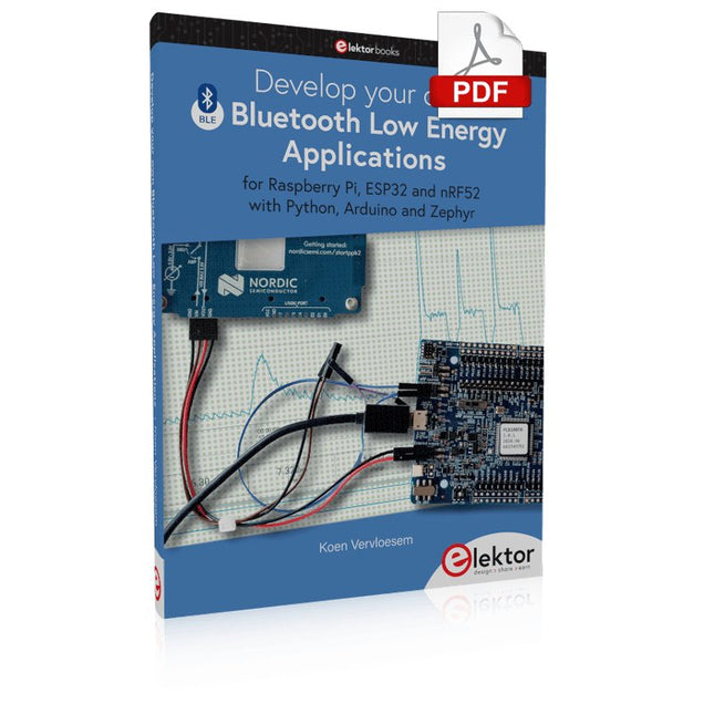
For Raspberry Pi, ESP32 and nRF52 with Python, Arduino and Zephyr
Bluetooth Low Energy (BLE) radio chips are ubiquitous from Raspberry Pi to light bulbs. BLE is an elaborate technology with a comprehensive specification, but the basics are quite accessible.
A progressive and systematic approach will lead you far in mastering this wireless communication technique, which is essential for working in low power scenarios.
In this book, you’ll learn how to:
Discover BLE devices in the neighborhood by listening to their advertisements.
Create your own BLE devices advertising data.
Connect to BLE devices such as heart rate monitors and proximity reporters.
Create secure connections to BLE devices with encryption and authentication.
Understand BLE service and profile specifications and implement them.
Reverse engineer a BLE device with a proprietary implementation and control it with your own software.
Make your BLE devices use as little power as possible.
This book shows you the ropes of BLE programming with Python and the Bleak library on a Raspberry Pi or PC, with C++ and NimBLE-Arduino on Espressif’s ESP32 development boards, and with C on one of the development boards supported by the Zephyr real-time operating system, such as Nordic Semiconductor's nRF52 boards.
Starting with a very little amount of theory, you’ll develop code right from the beginning. After you’ve completed this book, you’ll know enough to create your own BLE applications.