
Search results for "mooshimeter OR wireless OR 2 OR channel OR multimeter"
-

JOY-iT JOY-iT PS1440-C-Pro Programmable Laboratory Power Supply with RS485 (1440 W)
With the JOY-iT PS1440-C-Pro, you get a programmable laboratory power supply that delivers DC voltages ranging from 0.01 to 60 V and DC currents from 0.01 to 24 A at the voltage output. The intuitive control panel allows you to program, store, and recall up to 9 different DC voltage settings. You can also configure individual protection and limiting functions—such as overvoltage protection. All settings are easily adjusted via the keypad and/or rotary control and are clearly shown on the high-resolution 2.4" color display. For enhanced connectivity, the PS1440-C-Pro includes an RS485 interface for robust, long-distance communication. This makes it ideal for complex setups where signal stability, noise immunity, and reliable data transfer are critical. The included connector ensures a secure connection, improving the overall reliability and performance of your laboratory equipment setup. Features Complete device ready for immediate use RS485 interface Battery charging function Values can be entered conveniently via keypad Over current & over voltage protection adjustable Integrated RTC, NTC temperature sensor Included detailed documentation in English, German & French Specifications Input voltage 230 V Output voltage 060 V Output current 0-24 A Output power 0-1440 W Input voltage accuracy ±1% +5 digits Output voltage accuracy ±0.3% +3 digits Output current accuracy ±0.5% +5 digits Battery voltage ±0.5% +3 digits Input voltage measurement resolution 0.01 V Output voltage measurement resolution 0.01 V Current measurement resolution 0.01 V Battery voltage measurement resolution 0.01 V Response time in constant voltage mode 2 ms @ 0.1-5 A Load regulation in constant voltage mode ±0.1% +2 digits Load regulation in constant current mode ±0.1% +3 digits Measuring range electric charge 0-9999.99 Ah Measuring range energy 0-9999.99 Wh Statistical errors in electric charge & energy ±2% Output ripple 100 mV VPP @ 12 V150 mV VPP @ 24 V Sensor temperature detection range −10~100°C (0-200°F) Sensor temperature detection accuracy ±3°C (±6°F) Working mode Step-down operation Screen brightness setting Level 0-5, 6 levels in total Permissible working temperature −10~40°C (0-104°F) Dimensions 170 x 93 x 340 mm Included JOY-iT PS1440-C Power Supply 2-pin connector for RS485 interface Power cord Manual Downloads Datasheet MODBUS Protocol PC Software Driver for Windows
€ 499,00
Members: € 449,10
-

Elektor Digital Elektor 09-10/2025 (PDF) DE
Diese Ausgabe steht allen GOLD- und GREEN-Mitgliedern auf der ElektorMagazine-Website zum Download bereit! Sie sind noch kein Mitglied? Hier klicken! ESP32-Audio-Transceiver-Board (Teil 2)Drahtlose Audioübertragung Induktiver AM-SenderPIO des Pico in einem Arduino-Sketch Navigieren durch drahtlose ProtokolleEin technischer Leitfaden Satellitenverfolgung mit LoRaDas TinyGS-Netzwerk: Raumfahrtdaten gelangen zur Erde 4G-kompatible SMS-FernbedienungSteuern Sie Ihr Zuhause per Telefon aus der Ferne Hochgeschwindigkeits-TastkopfHochohmige Eingänge für Signale bis 200 MHz Aus dem Leben gegriffenKafka KrakenSDREin phasenkohärenter SDR-Empfänger Geschwindigkeitstests mit dem RP2350Lohnt sich der Umstieg von Raspberry Pi Pico 1 auf Version 2? Kontaktlose E-Feld-Messungen (2)Ein Laser-Vibrometer zur Erfassung der Membranschwingungen Quarze und OszillatorenQuarzgenauigkeit durch die Kondensatorwahl verbessern Aller Anfang ...... ist gar nicht schwer: Spezielle Audio-ICs Einstieg ins Programmieren von Selbstbauprojekten SPECTRAN® V6 MobileModular konfigurierbarer Echtzeit-Spektrum-Analyzer für zuverlässige Messungen in allen Frequenzbereichen Die Zukunft der KI wird in Silizium geschmiedetEin Interview mit Anastasiia Nosova Autonomer Sensorknoten v2.0 (Systemarchitektur)Solarbetriebene Sensorplattform mit integriertem GPS, LoRaWAN und weiteren Funktionen Präzise PositionsbestimmungBluetooth Channel Sounding ausprobiert Die Zukunft der Wireless-KommunikationDie ultradünnen Festkörperbatterien von BTRY Testgetriebene Programmierung in der Firmware-Entwicklung Handy-gesteuertes ModellautoWLAN + ESP32 + Smartphone = Fernsteuerung 2025: Eine KI-OdysseeKI-Denkmodelle: die Gedankenketten-Revolution Solarladeregler mit MPP-TrackingTeil 3: Software und Inbetriebnahme Web-Streaming-Kamera mit Raspberry Pi ZeroVerwendung des ZeroTier-VPN
€ 11,90
-

Elektor Digital Elektor July/August 2026 (PDF) EN
Elektor GREEN and GOLD members can download their digital edition here. Not a member yet? Click here. MultiRF Dev BoardA Platform for Evaluating Short- and Long-Range Wireless Protocols Elektor at 65Disrupting Electronics Since 1961 Wi-Fi-Based Person Detection on an ESP32When Your Router Becomes a Motion Sensor Wireless ScalesFour Small Scales = One Big Scale Walter, the Compact IoT ModuleESP32-S3 SoC, LTE-M/NB-IoT 5G Modem, and GNSS Receiver 3- and 4-Wire RTD Sensors ConditioningWith Full-Scale Adjustment and Cable Compensation 3-in-1 2-Channel Oscilloscope/Generator/MultimeterA Review of The Fnirsi 2D15P electronica Fast Forward 2026 Invites Startups and Industry Partners EcologgingA Modular Environmental IoT Station for Field Research Wireless Connectivity in Medical ApplicationsAlways on the Pulse with Bluetooth LE AudiotronicsHum Reduction Increasing Agricultural Efficiency with AI Modeling and SensorsBoosting Agricultural Productivity OPC UA — An OverviewPlatform-Independent Data Exchange Redox Meter Instrumentation Amplifier for Physics and Engineering Experiments Active Differential Audio FiltersFor Professional Crossovers and More Elektor Community Perspectives on IoT & Sensors Telegram-Controlled Water Heater Interface ModuleA Solution Based on an ESP32 and Arduino Software 2026: An AI OdysseyWhatever Happened to Fuzzy Logic? Err-lectronics Alarm Signal Injector Plus PowerTools for Finding Broken Wires
€ 9,50
-

Red Pitaya Red Pitaya STEMlab 125-14 PRO Gen 2 Starter Kit (incl. Book)
This bundle includes the Red Pitaya STEMlab 125-14 PRO Gen 2 Starter Kit and the new book "Experimenting with Red Pitaya STEMlab Gen 2". The Red Pitaya STEMlab 125-14 PRO Gen 2 Starter Kit is a powerful and flexible platform for signal processing, data acquisition, and electronic measurement applications. Designed for engineers, developers, researchers, and educators, this kit provides everything required to start building advanced measurement and control systems. At the core of the kit is the STEMlab 125-14 PRO Gen 2 board, an upgraded and ultra-lightweight development platform. Powered by the Xilinx Zynq-7010 SoC with 512 MB of RAM, it combines FPGA programmability with ARM processing power to enable high-performance instrumentation and custom signal-processing solutions. The board offers 14-bit ADC and DAC resolution, a 125 MS/s sampling rate, an input range of ±20 V, and up to 60 MHz bandwidth. Its improved low-noise analog front-end, USB-C connectivity, and compact design make it suitable for demanding applications such as RF development, radar systems, photonics research, software-defined radio (SDR), and industrial automation. The Starter Kit includes all essential accessories for immediate use: a microSD card with preinstalled operating system, power supply, Ethernet cable for remote access, two 100 MHz oscilloscope probes, and SMA-to-BNC adapters for flexible signal connections. The Red Pitaya STEMlab 125-14 PRO Gen 2 Starter Kit is an excellent platform for rapid prototyping, FPGA development, measurement instrumentation, and advanced electronics experimentation. Features 14-bit ADC and DAC resolution 125 MS/s sampling rate ±20 V input range Up to 60 MHz bandwidth Xilinx Zynq-7010 SoC (FPGA + ARM processor) 512 MB RAM Low-noise analog front- and back-ends Applications RF development and testing Radar and wireless systems Software-defined radio (SDR) Photonics and optical research Industrial automation and control systems Signal analysis and instrumentation Rapid prototyping of electronic measurement systems Specifications Processor Dual-core ARM Cortex-A9 FPGA AMD Xilinx Zynq-7010 SoC RAM 512 MB (4 Gb) Storage microSD card (up to 32 GB) Operating System Linux-based Red Pitaya OS ADC Resolution 14-bit DAC Resolution 14-bit Bandwidth 60 MHz (DC) Sampling Rate 125 MS/s Analog Input Channels 2 Analog Output Channels 2 Input Voltage Range ±1 V (LV) / ±20 V (HV) Input Impedance 1 MΩ / 10 pF Output Voltage Range ±1 V Ethernet 1x Gigabit Ethernet (RJ45) USB 2x USB-C 2.0 (for power and console) Digital I/O 16x GPIO (3.3 V) Communication Interfaces I²C, SPI, UART, CAN Power Supply 5 V/3 A via USB-C Dimensions 106.8 x 60.0 x 17.9 mm Included 1x Red Pitaya STEMlab 125-14 PRO Gen 2 board 2x 100 MHz oscilloscope probes 2x SMA-to-BNC adapters 1x microSD card with preinstalled OS 1x USB-C Power supply 1x Ethernet cable Downloads Documentation Schematics Book: Experimenting with Red Pitaya STEMlab Gen 2 With this new book, Red Pitaya goes beyond a versatile board. It becomes a powerful laboratory instrument for precision measurement, analysis, and control. From the fundamentals of electronic project development, monitoring, control, and design to testing, this book walks you step-by-step through everything you need to know to harness the full potential of Red Pitaya hardware and software. The book presents real-time, FPGA-based projects that are developed on a PC using the Vivado environment, then transferred to the Red Pitaya for execution and testing. You will learn about enhanced performance, expanded I/O capabilities, improved FPGA features, and advanced connectivity options that open up new frontiers for precision measurement, monitoring, and control in your embedded applications. Inside the book you will discover: A deep dive into Red Pitaya architecture and hardware design Electronic experiments using Red Pitaya for measurement and monitoring Hands-on projects using the Python programming language Practical guidance for FPGA programming using Red Pitaya Red Pitaya FPGA projects using the Verilog HDL under Vivado IDE Practical design of electronic projects including measurement and testing Step-by-step examples that bridge theory and real-world implementation Whether you are designing your own electronic circuits, developing signal analysis tools, or creating real-time control or monitoring systems, this book provides you the knowledge and confidence you need to fully learn and customize the Red Pitaya platform.
€ 799,00
Best Price
-

Elektor 07-08/2026 (DE)
Diese Ausgabe steht allen GOLD- und GREEN-Mitgliedern auf der ElektorMagazine-Website zum Download bereit! Sie sind noch kein Mitglied? Hier klicken! MultiRF-EntwicklungsboardEine Plattform zur Evaluierung drahtloser Protokolle für kurze und lange Reichweiten Elektor wird 65Elektronik im Wandel seit 1961 WLAN-basierte Personenerkennung mit dem ESP32Wenn der Router zum Bewegungsmelder wird Drahtlose WaagenVier kleine Waagen = eine große Waage Walter, das kompakte IoT-ModulESP32-S3-SoC, LTE-M/NB-IoT-5G-Modem und GNSS-Receiver 3- und 4-Draht-RTD-Sensoren konditionierenMit Vollbereichsabgleich und Kabelkompensation Drei in einem: 2-Kanal-Oszilloskop/Generator/MultimeterEin Test des Fnirsi 2D15P electronica Fast Forward 2026 für Start-ups und Industriepartner EcologgingEine modulare IoT-Messstation für Umweltdaten Drahtlos-Anbindung für MedizingeräteImmer am Puls mit Bluetooth LE AudiotronicsBrummunterdrückung Mehr Effizienz in der Landwirtschaft durch KI-Modelle und SensorenSteigerung der landwirtschaftlichen Produktivität OPC UA – ein ÜberblickPlattformunabhängiger Datenaustausch Redox-Meter Instrumentenverstärker für Physik- und Engineering-Experimente Aktive differentielle Audio-FilterFür professionelle Frequenzweichen und mehr Elektor-Community-Tipps zu IoT und Sensoren Telegram-gesteuerter WarmwasserbereiterEine Lösung mit ESP32 und Arduino-Software 2026: Eine KI-OdysseeWas wurde eigentlich aus der Fuzzy-Logik? Projekt 2.0 Alarmsignalinjektor + PowerTools zum Suchen verdeckt verlegter Leitungen
€ 15,90
-

Rigol Rigol DS1054Z 4-ch Oscilloscope (50 MHz)
Specifications Bandwidth: 50 MHz Analog Channels: 4 Real-time sample rate up to 1 GS/s Memory depth up to 24 Mpts Up to 30,000 wfms/s waveform capture rate Up to 60,000 frames hardware real-time waveform recording and playback functions Innovative 'UltraVision' technology Various trigger and bus decoding functions Low noise floor, vertical scale range: 1 mV/div to 10 V/div Various interfaces: USB Host&Device, LAN (LXI), AUX Compact size, light weight, easy to use 7 inch WVGA (800x480) TFT LCD, intensity graded color display Included 1x Rigol DS1054Z Oscilloscope 1x Power cord 1x USB cable 4x PVP2150 Passive oscilloscope probe (150 MHz)
€ 409,00
-

JOY-iT Joy-Pi Advanced Development Platform (incl. Raspberry Pi 4, 8 GB)
The Joy-Pi Advanced is a compact and powerful device that allows you to realize your projects quickly and easily. Whether you already have a lot of experience, or next to none, the Joy-Pi Advanced lets you unleash your creativity. Thanks to its compatibility with a wide range of platforms, including Raspberry Pi, Raspberry Pi Pico, Arduino Nano, BBC micro:bit, and NodeMCU ESP32, you can easily and quickly access your preferred platform. In addition, the Joy-Pi Advanced features more than 30 stations, lessons, and modules, giving you an unlimited variety of ways to get your projects done. With the self-developed learning center, you can not only improve your skills but also create new projects. The learning center offers a wealth of information and tutorials that will guide you step by step through your projects. Joy-Pi Advanced is characterized in particular by its intelligent switch units, which allow an extended use of the available pins. A total of three switch units are integrated, each equipped with 12 individual switches that provide precise control of the connected sensors and modules. This system solves the well-known problem of limited pin count that occurs with conventional microcontrollers. The switch units allow you to operate a large number of sensors and modules in parallel by switching them on and off individually. This simulates multiple pin assignment, allowing you to exploit the full power of your projects without compromising functionality. By combining innovative adapter boards and the micro:bit slot, you can achieve seamless compatibility with a wide range of microcontrollers such as Raspberry Pi Pico, NodeMCU ESP32, micro:mit and Arduino Nano. The specially developed adapter boards are designed to perfectly match the respective microcontroller. By plugging the microcontroller onto the appropriate adapter board and then plugging it into the micro:bit slot, the Joy-Pi Advanced quickly and easily becomes compatible with the different microcontrollers. This allows seamless integration of your preferred platform and the ability to combine the strengths of the different microcontrollers in your projects. This way, you can fully focus on your creative projects without worrying about the compatibility of different microcontrollers. The Joy-Pi Advanced simplifies the development process and gives you the possibility to design your projects flexibly and individually. Features Highly integrated development platform & learning center Fast, easy & wireless combination of various sensors & actuators Installation option for Raspberry Pi 4 Compatible with various microcontrollers Self-developed, didactic learning platform for Raspberry Pi & Windows Specifications Compatible to Raspberry Pi 4, Arduino Nano, NodeMCU ESP32, BBC micro:bit, Raspberry Pi Pico Installed sensors, actuators & components 39 Learning platform Over 40 entries in the know-ledge database, 10 projects, 10 learning tasks, 14 visions Displays 7-segment display, 16x2 display, 1.8“ TFT display, 0.96" OLED display, 8x8 RGB matrix Sensors DS18B20, shock sensor, hall sensor, barometer, sound sensor, gyroscope, PIR sensor, Light barrier, NTC, Light sensor, 6x touch sensor, color sensor, ultrasonic distance sensor, DHT11 temperature & humidity sensor Control Joystick, 5x switches, potentiometer, rotary encoder, 4x4 button matrix, relays, PWM fan Motors Servo interface, Stepper motor interface, Vibration motor Measuring & conversion modules Analog-Digital Converter, Level converter, voltmeter, Variable voltage supply Other components RTC real time clock, buzzer, EEPROM memory, infrared receiver, breadboard, RFID reader Adapter boards Adapter for NodeMCU ESP32, Arduino Nano & Raspberry Pi Pico, Board connectors for Raspberry Pi & External Boards Electronic components Infrared remote control, RFID chip, RFID card, 6x alligator clips, microSD card reader, servo motor, stepper motor, 32 GB microSD card Components 40x resistors, 3x green LEDs, 3x yellow LEDs, 3x red LEDs, 1x transistor, 5x buttons, 1x potentiometer, 2x capacitors Other accessories Screw assortment, screwdriver, accessory storage bag, power supply & power cable, servo mount Power supply Built-in power supply: 36 W, 12 V, 3 A Case connector: Small device plug C8 Voltage outputs 12 V, 5 V, 3.3 V, Variable voltage output (2-11 V) Data buses & signal outputs I²C, SPI, Analog to digital converter Battery (RTC) CR2032 Dimensions 327 x 200 x 52 mm Included Raspberry Pi 4 (8 GB RAM) Downloads Joy-Pi website Datasheet Manual
€ 529,00€ 469,00Best Price
-

Elektor Bundles Arduino UNO Q (Bundle)
This bundle includes the Arduino UNO Q (2 GB) and the book "Arduino UNO Q and AI". The Arduino UNO Q is the first UNO board with a hybrid dual-brain architecture, combining a powerful Linux processor with a real-time microcontroller – bringing advanced computing and precise control together on one board. Powered by a Qualcomm Dragonwing QRB2210 MPU running Debian Linux and a STM32U585 MCU for real-time tasks, the UNO Q is built for next-generation applications. From Edge Computing and AI to robotics and automation, it delivers high performance without sacrificing ease of use. Simply connect your peripherals and get started – no extra hardware required. Features Dual-core architecture: Linux MPU + real-time MCU Qualcomm Dragonwing QRB2210 with Debian Linux support STM32U585 microcontroller for deterministic control Runs Arduino sketches via Zephyr OS Ideal for AI, IoT, robotics, and industrial projects Specifications Microprocessor (MPU) Qualcomm Dragonwing QRB2210:Quad-core Arm Cortex-A53 @ 2.0 GHzAdreno GPU 3D graphics accelerator2× ISP (13 MP + 13 MP or 25 MP) @ 30 fps Microcontroller (MCU) STM32U585Arm Cortex-M33 up to 160 MHz2 MB flash memory786 KB SRAM RAM 2 GB LPDDR4 Power Supply From USB-C connector 5 V max at 3 AInput Voltage (VIN): 7-24 V Storage 16 GB eMMC USB 1× USB-C port with host/device role switching, power role switch and video output Connectivity Wi-Fi 5 (2.4/5 GHz) with onboard antennaBluetooth 5.1 with onboard antenna Interfaces I²C/I³CSPIPWMCANUARTPSSIGPIOJTAGADC Video Video output support via USB-CMIPI DSI pins on JMEDIA header Extra 4× RGB user-controllable LEDs8×13 Blue LED Matrix1× Qwiic connector voltage 3V3, I²C1× User push-buttonJCTL: MPU Remote Debug connector Audio Microphone IN / Headphone OUT / Line OUT on JMISC MPU Operating System Linux Debian OS with upstream support Real-time Operating System Arduino Core on Zephyr OS Containerization Docker and Docker Compose support Support Operating Systems for Arduino App Lab Windows: Windows 10 or later (64-bit)macOS: macOS 11 or later (64-bit)Linux: Ubuntu 22.04 or later, and Debian Trixie (64-bit) Dimensions 68.85 × 53.34 mm (UNO form factor) Downloads Datasheet User Manual Pinout Schematics Book: Arduino UNO Q and AI – Learn to Build Intelligent Embedded Systems Build smarter embedded systems with Arduino UNO Q. This book gives you the tools, knowledge, and confidence to turn ideas into intelligent, working solutions using the Arduino UNO Q platform. Discover how to build intelligent embedded systems with the Arduino UNO Q and AI. Unlock the full potential of the Arduino UNO Q, a next-generation platform that combines the real-time power of the STM32U585 microcontroller with the flexibility of a Qualcomm Dragonwing QRB2210 microprocessor. Learn how to rapidly prototype real-world applications using the Arduino IDE for low-level embedded control and Python in Arduino App Lab for high-level development. Build confidence through hands-on projects that guide you step by step from basic board features to complete working systems. Explore ready-to-use, AI based Arduino App Lab examples and see how they can jump-start your development and reduce time to deployment. Step into the world of Edge AI with a clear, practical introduction to Edge Impulse Studio—no prior AI experience required. Follow a complete, real-world workflow to create a Keyword Spotting AI application, covering data collection, model training, optimization, and on-device inference using the Edge Impulse Studio. Bridge the gap between embedded systems and machine learning and learn how to bring intelligence directly onto your hardware. Perfect for embedded engineers, educators, students, and makers looking to stay ahead in AI-enabled product development. This bundle contains: Arduino UNO Q (2 GB) (normal price: €50) Book: Arduino UNO Q and AI (normal price: €35)
€ 84,95€ 74,95Best Price
-
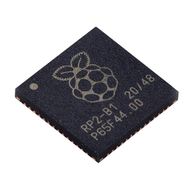
Raspberry Pi Foundation Raspberry Pi RP2040 Microcontroller (10 pcs)
Specifications Dual ARM Cortex-M0+ @ 133 MHz 264 kB on-chip SRAM in six independent banks Support for up to 16 MB of off-chip Flash memory via dedicated QSPI bus DMA controller Fully-connected AHB crossbar Interpolator and integer divider peripherals On-chip programmable LDO to generate core voltage 2x on-chip PLLs to generate USB and core clocks 30x GPIO pins, 4 of which can be used as analogue inputs Peripherals 2x UARTs 2x SPI controllers 2x I²C controllers 16x PWM channels USB 1.1 controller and PHY, with host and device support 8x PIO state machines What you'll get 10x bare RP2040 chips
€ 7,95€ 3,18Best Price
-
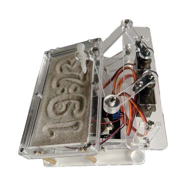
Elektor Labs Elektor Sand Clock for Raspberry Pi Pico
Raspberry Pi-based Eye Catcher A standard sand clock just shows how time passes. In contrast, this Raspberry Pi Pico-controlled sand clock shows the exact time by “engraving” the four digits for hour and minute into the layer of sand. After an adjustable time the sand is flattened out by two vibration motors and everything begins all over again. At the heart of the sand clock are two servo motors driving a writing pen through a pantograph mechanism. A third servo motor lifts the pen up and down. The sand container is equipped with two vibration motors to flatten the sand. The electronic part of the sand clock consists of a Raspberry Pi Pico and an RTC/driver board with a real-time clock, plus driver circuits for the servo motors. A detailed construction manual is available for downloading. Features Dimensions: 135 x 110 x 80 mm Build time: approx. 1.5 to 2 hours Included 3x Precut acrylic sheets with all mechanical parts 3x Mini servo motors 2x Vibration motors 1x Raspberry Pi Pico 1x RTC/driver board with assembled parts Nuts, bolts, spacers, and wires for the assembly Fine-grained white sand
€ 49,95€ 39,95Best Price
-

Siglent Siglent SDS1104X-E 4-ch Oscilloscope (100 MHz)
The Siglent SDS1104X-E employs a new generation of SPO (Super Phosphor Oscilloscope) technology that provides excellent signal fidelity and performance. The system noise is also lower than similar products in the industry. It comes with a minimum vertical input range of 500 uV/div, an innovative digital trigger system with high sensitivity and low jitter, and a waveform capture rate of 400,000 frames/sec (sequence mode). The SDS1104X-E also employs a 256-level intensity grading display function and a color temperature display mode not found in other models in this class. SIGLENT’s latest oscilloscopes offering supports multiple powerful triggering modes including serial bus triggering. Serial decoding is free and includes IIC, SPI, UART, CAN, and LIN. History waveform recording and sequential triggering enable extended waveform recording and analysis. Another powerful addition is the new 1 Mpt FFT math function that gives the SDS1104X-E very high frequency resolution when observing signal spectra. Features Intelligent trigger: Edge, Slope, Pulse Width, Window, Runt, Interval, Timeout (Dropout), and Pattern Free Serial bus triggering and decoding:IIC, SPI, UART, RS232, CAN, and LIN Video triggers and supports HDTV Low background noise and 500 μV / div to 10 V / div voltage scales 10 types of one-button shortcuts, supports Auto Setup, Default, Cursors, Measure, Roll, History, Display/Persist, Clear Sweep, Zoom and Print Segmented acquisition (Sequence) mode, dividing the maximum record length into multiple segments (up to 80,000), according to trigger conditions set by the user, with a very small dead time segment to capture the qualifying event. History waveform record (History) function, the maximum recorded waveform length is 80,000 frames Automatic measurement function on 38 parameters, supports Statistics, Gating measurement, Math measurement, History measurement and Ref measurement 1 Mpts FFT True measurement and math can use all 14 Mpts of memory Preset key can be customized for user settings or factory “defaults” Security Erase mode Highspeed hardware based Pass/ Fail function Large 7-inch TFT-LCD display with 800 * 480 resolution Multiple interface types: USB Host, USB Device (USB-TMC), LAN (VXI-11), Pass / Fail, Trigger Out Supports SCPI remote control commands Multi-language display and embedded help Browser control/onboard webpage for software free monitoring (4 channel models only) Included 1x Siglent SDS1104X-E Oscilloscope 4x 100 MHz probes 1x Guarantee Card 1x Power Cord 1x USB Cable 1x Quick Start Guide Downloads Datasheet Manual Programming Guide
€ 508,71
-
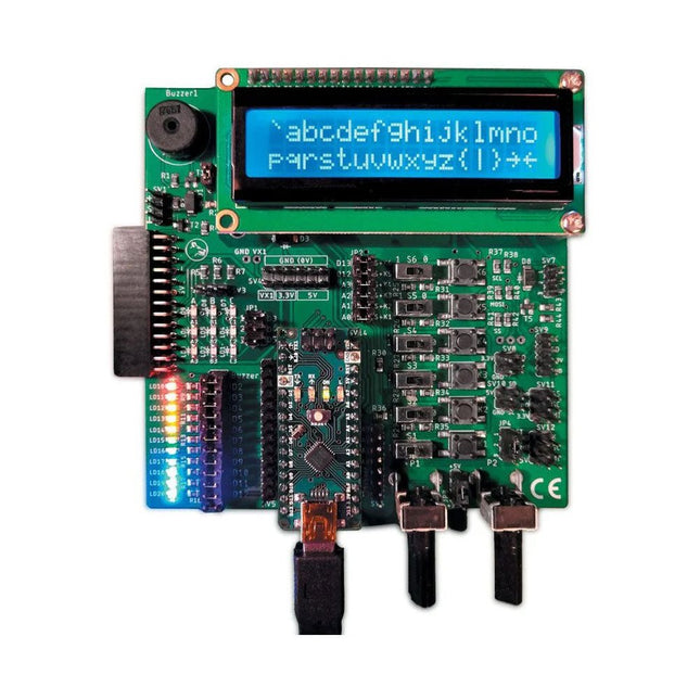
Elektor Labs Elektor Arduino Nano MCCAB Training Board
The Elektor Arduino Nano MCCAB Training Board contains all the components (incl. Arduino Nano) required for the exercises in the "Microcontrollers Hands-on Course for Arduino Starters", such as light-emitting diodes, switches, pushbuttons, acoustic signal transmitters, etc. External sensors, motors or assemblies can also be queried or controlled with this microcontroller training system. Specifications (Arduino Nano MCCAB Training Board) Power Supply Via the USB connection of the connected PC or an external power supply unit (not included) Operating Voltage +5 Vcc Input Voltage All inputs 0 V to +5 V VX1 and VX2 +8 V to +12 V (only when using an external power supply) Hardware periphery LCD 2x16 characters Potentiometer P1 & P2 JP3: selection of operating voltage of P1 & P2 Distributor SV4: Distributor for the operating voltagesSV5, SV6: Distributor for the inputs/outputs of the microcontroller Switches and buttons RESET button on the Arduino Nano module 6x pushbutton switches K1 ... K6 6x slide switches S1 ... S6 JP2: Connection of the switches with the inputs of the microcontroller Buzzer Piezo buzzer Buzzer1 with jumper on JP6 Indicator lights 11 x LED: Status indicator for the inputs/outputs LED L on the Arduino Nano module, connected to GPIO D13 JP6: Connection of LEDs LD10 ... LD20 with GPIOs D2 ... D12 Serial interfacesSPI & I²C JP4: Selection of the signal at pin X of the SPI connector SV12 SV9 to SV12: SPI interface (3.3 V/5 V) or I²C interface Switching output for external devices SV1, SV7: Switching output (maximum +24 V/160 mA, externally supplied) SV2: 2x13 pins for connection of external modules 3x3 LED matrix(9 red LEDs) SV3: Columns of the 3x3 LED matrix (outputs D6 ... D8) JP1: Connection of the rows with the GPIOs D3 ... D5 Software Library MCCABLib Control of hardware components (switches, buttons, LEDs, 3x3 LED matrix, buzzer) on the MCCAB Training Board Operating Temperature Up to +40 °C Dimensions 100 x 100 x 20 mm Specifications (Arduino Nano) Microcontroller ATmega328P Architecture AVR Operating Voltage 5 V Flash Memory 32 KB, of which 2 KB used by bootloader SRAM 2 KB Clock Speed 16 MHz Analog IN Pins 8 EEPROM 1 KB DC Current per I/O Pins 40 mA on one I/O pin, total maximum 200 mA on all pins together Input Voltage 7-12 V Digital I/O Pins 22 (6 of which are PWM) PWM Output 6 Power Consumption 19 mA Dimensions 18 x 45 mm Weight 7 g Included 1x Elektor Arduino Nano Training Board MCCAB 1x Arduino Nano
€ 79,95€ 69,95Best Price


