
Search results for "linear OR audio OR volume OR 10"
-

Elektor Digital Elektor Circuit Special 2026 (PDF) EN
Elektor GREEN and GOLD members can download their digital edition here. Not a member yet? Click here. A Current Source for Testing (Z-)DiodesChecking Z-Diodes from 1 to 54 V @ 1 to 50 mA ESD Strap TesterA Bench Tool with Pass, Borderline, and Fail Indication Power Supply Transient Response TesterA Repeatable Step-Load Generator for Bench Power Supplies Euclidean Sequencer Without a MicrocontrollerTrigger Patterns and CV Sequences with Simple CMOS Logic LED Flashing Light for Gates and More with an Audible Alert Need PCBs? The Elektor PCB Service Has You Covered. Toothbrush TimerUsing a Tiny PIC A Contactless Magnetic Combination LockWith the AS5600 Rotary Position Sensor Low-Noise Battery-Powered PreamplifierFor Dynamic Microphones The Arduino Nano TestLabMeasurement, Control, and Regulation Rhythmic Bass LightEmphasize the Rhythm of Your Music Low-Cut FilterNo Risk of Audio Feedback on Your System Precise 1 Hz Square Wave Generator for BreadboardsA Reliable CMOS-Based Clock Source 555 Upside DownDuty Cycles Down to Zero From Halfgeleidergids to Circuit Specials65 Years of Electronics Innovation Electrical IsolationCAN Interface with Digital Isolator and Power Module SpongillatorA Sponge-Based Oscillator True Random Number GeneratorWith Integrated Chi-Square Test 3D Viewer for HTML pagesSimple, and Almost Without Code Programming with TLScriptA Scripting Language for Measurement, Testing, and Control Circuit Design: Tips from Experts FeedbackWhat Is It and Why Is It Important? One Board, Endless Ideas: Arduino UNO QFrom Retro Gaming to Real-Time Environmental Monitoring How to Fix a Donut Antenna Standby KillerA Real On/Off Switch for Your TV Battery TestingMeasuring Batteries with the Arduino Nano Power Supply for Audio Power AmplifiersA Good Power Supply Without Mains Hum Prototyping Boards for RFFast Setups with DIY Prototyping Boards T3 Surge ProtectionA Type 3 Spike Suppressor for Your Sensitive Equipment IoT Room Thermostat BoardWith ESP32-C3/S3-Based Xiao MCU module From Rigid to SmartFlexible and Printed Electronics — Between Vision and Industrial Reality
€ 9,50
-
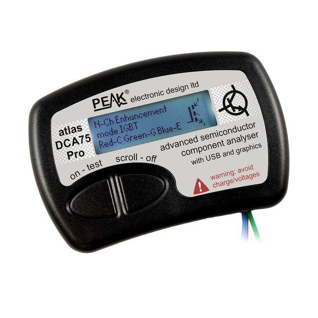
Peak Peak Atlas DCA75 Pro (Advanced Semiconductor Analyzer)
The DCA75 Pro is a great instrument that combines ease-of-use with amazing features. It can automatically identify a huge range of semiconductors, automatically identify pinouts and measure detailed parameters. Features Built-in graphics display (now backlit) to show detailed schematic of the component you're testing as well as pinout and measurement data USB connectivity to allow curve tracing, data storage/retrieval and device matching on your Windows PC (Windows 7 and higher) Single internal AAA alkaline cell for standalone operation Component Support Bipolar transistors (NPN/PNP inc Silicon/Germanium) Darlington transistors (NPN/PNP) Enhancement mode MOSFETs (N-Ch and P-Ch) Depletion mode MOSFETs (N-Ch and P-Ch) Junction FETs (N-Ch and P-Ch). Both symmetrical and asymmetrical types Enhancement IGBTs (N-Ch and P-Ch) Diodes and diode networks (2 and 3 lead types) Zener diodes (up to about 9 V) Voltage regulators (up to about 8 V) LEDs and bi-colour LEDs (2 lead and 3 lead types) Low power sensitive Triacs and Thyristors (<10 mA trigger and hold) Measurements BJT current gain (hFE) BJT base emitter voltage (Vbe) BJT collector leakage current MOSFET on and off gate threshold voltages MOSFET transconductance JFET pinch-off voltage JFET transconductance JFET IDSS (drain current for Vgs=0) IGBT on and off gate threshold voltages IGBT transconductance Voltage regulator output voltage Voltage regulator quiescent current consumption Voltage regulator drop-out voltage Zener voltage Diode forward voltage drop Specifications Analyzer type Semiconductor components Component detection Automatic Pinout detection Automatic, connect any way round Display type Graphic LCD (now backlit) Interface type USB for optional PC connection PC functions Curve tracing (Windows 7 and higher) Software Included on USB drive for Windows 7 and higher Battery Single AAA cell (supplied) Included Peak Atlas DCA75 Pro PC software on a USB Flash Drive for Windows 11, 10, 8, 7, XP Micro USB cable Fitted universal premium hook probes AAA Alkaline battery Downloads Datasheet (EN) User Guide (EN) User Guide (IT) Software Installation Guide (EN) Software and Firmware Package
€ 192,39
-

Elektor Digital Audio 3 (PDF)
Inhalt Röhrentechnik Entwicklung von DCMB-Verstärkern: Die Regeln der Kunst 50-W-Gegentaktverstärker mit EL34 und Autobias: Einmal und nie wieder – der Ruhestrom-Abgleich Kann ein Röhrenverstärker Mikrodetails wiedergeben: Bremst der Ausgangsübertrager die Auflösung Doppelter Röhrentester Comra BT0801: Testen und Selektieren in einem Rutsch 300B-Single-Ended Stereo-Verstärker: Kompromisslose Schaltungsauslegung mit der Triode schlechthin Lautsprecher Freedom von Monacor International: Gelungene Kombination aus Horn und Reflexsystem Symphonie von Visaton: Großer Auftritt der großen Kalotte Apollon von ASE: Das Flaggschiff mit Scan Speaks Illuminator-Bestückung TL-Sub von Quint-Audio: Der Subwoofer für reichlich Druck in der untersten Oktave Hans von Henkjan Olthuis: Zweiwege-Standbox mit Design-Qualität Avisio vom Lautsprechershop Strassacker: Der Einstand in die Home-Cinema-Riege XT612 von Ground Sound: Vollaktive Box, die selber messen kann Der Markt: Neues und Nützliches Halbleitertechnik DIY CD-Player von Tentlabs: Digitaltechnik und Röhrenschaltungen geschickt kombiniert SMPS 180 von Hypex: Das Schaltnetzteil zur Klasse-D-Technik UcD 2k von Hypex: Klasse-D-Technik für die PA im kW-Bereich
€ 16,90
Members: € 15,21
-

Elektor Publishing Software Defined Radio zum Selbstbau
Praktischer Einstieg mit Arduino, GnuRadio und FPGA Das Thema „Software Defined Radio“ ist facettenreich: Neben der Schaltungstechnik ist auch eine Einarbeitung in die Programmierung von Hardware und PC wichtig. Ein schrittweises Vorgehen erleichtert Ihnen den Einstieg. Mit dem im Buch vorgestellten modularen „RF Bricks“-Konzept werden Sie zum Architekten Ihrer Signalkette. Auf einem Chassis angeordnet gewährleisten die Module einen soliden und gut abgeschirmten Aufbau, den Sie einfach verändern und mit eigenen Ideen anreichern können. Der skalierbare Aufbau bildet Ihr Blockschaltbild auch mechanisch ab – die so gewonnene Übersicht kann in der Aus- und Weiterbildung nützlich sein. Ein Arduino in Ihrem Chassis kommuniziert nach einigen Anpassungen mit üblichen SDR-Programmen, z. B. SDRCPP, GQRX und CubicSDR auf einer Linux-Plattform. Damit können Sie Ihren Empfänger direkt per Mausklick abstimmen. Wenn Sie Blockschaltbilder mögen, ist GnuRadio ein natürlicher Partner der „RF Bricks“. Mit einem selbst programmierten Python-Block gelingt Ihnen in GnuRadio die Fernsteuerung Ihres Empfängers. Im GnuRadio-Universum können Sie Ihre GUI stufenweise ausbauen, behalten dabei aber immer volle Kontrolle über die inneren Abläufe des Programms. Mit einem FPGA können zeitaufwändige Operationen auch direkt in die Hardware verlagert werden. Sie bauen stufenweise einen Doppelsuperhet auf und entwickeln die Filterkoeffizienten für FIR-Filter mit Scilab. Das in VHDL realisierte Weaver-Schema rundet diesen Empfänger ab, der mit hoher Empfindlichkeit und Dynamik aufwarten kann. Mit dem gewonnen Überblick und Ihrer neuen Hardware können Sie die einzelnen Aspekte des Themenkomplexes SDR beliebig weiter vertiefen. Downloads Software
€ 44,80
Best Price
-

Elektor Digital Verstärker in Röhrentechnik (PDF)
Selbst für so manchen an der Elektronik Interessierten ist die Röhrentechnologie ein technischer Anachronismus, Röhrenverstärkern könne doch allenfalls noch ein Ehrenplatz im Museum zugewiesen werden. Das ist einerseits durchaus richtig, Röhren haben eine fast hundertjährige Geschichte hinter sich. Seit der Erfindung des Transistors, der Öffentlichkeit vorgestellt am 23.12.1947, war das Ende der Röhrenära eingeläutet. Von da ab sollte es immerhin noch mehr als zwanzig Jahre dauern, bis die Röhren – von Sonderanwendungen abgesehen – aus dem Blickfeld des durchschnittlichen Elektronikgeräte-Konsumenten weitgehend verschwunden waren. So gesehen, sind Röhren tatsächlich veraltet, haben Röhren Museumcharakter. Niemand käme wohl heute auch mehr ernsthaft auf die Idee, sein leistungsfähiges Digitalmessinstrument gegen ein Röhrenvoltmeter auszutauschen; hochintegrierte Halbleiterchips können nun einmal bei eigentlich unvergleichlich geringerem Platz- und Energiebedarf mehr. Auf die Überlegenheit moderner Mikroprozessoren in Bezug auf Rechengeschwindigkeit und Speicherkapazität braucht man eigentlich gar nicht zu verweisen. Der erste programmgesteuerte Elektronikrechner Eniac im Jahre 1945 wog rund 30 Tonnen, enthielt neben insgesamt etwa 500.000 übrigen Bauteilen 18.000 Elektronenröhren und füllte eine mittlere Halle. In einem Bereich allerdings, im Bereich der Audio-Signalverarbeitung, haben Röhren bei Kennern und Musikliebhabern ihre Bedeutung bewahrt oder zurückerlangt: Für eine mittlerweile gestiegene Zahl kritischer Hi-Fi-Hörer steht "ihr" Röhrenverstärker im Zentrum der heimischen Anlage und für unzählige Musiker ist der Gitarrenröhrenverstärker nach wie vor ein Garant für guten Sound. Dieses Book spricht jeden an, der sich für Röhren aus den verschiedensten Gründen interessiert, den "Audiophilen" ebenso wie den aktiven Musiker und natürlich auch den, der einfach nur etwas über die Geschichte und die gegenwärtige Anwendbarkeit von Röhren wissen will. Aus diesem Grund hat der Autor sowohl Informationen über ein interessantes Stück Technikgeschichte als auch – praxisorientiert – Schaltungen und Selbstbauanleitungen zusammengetragen.
€ 32,80
Members: € 29,52
-
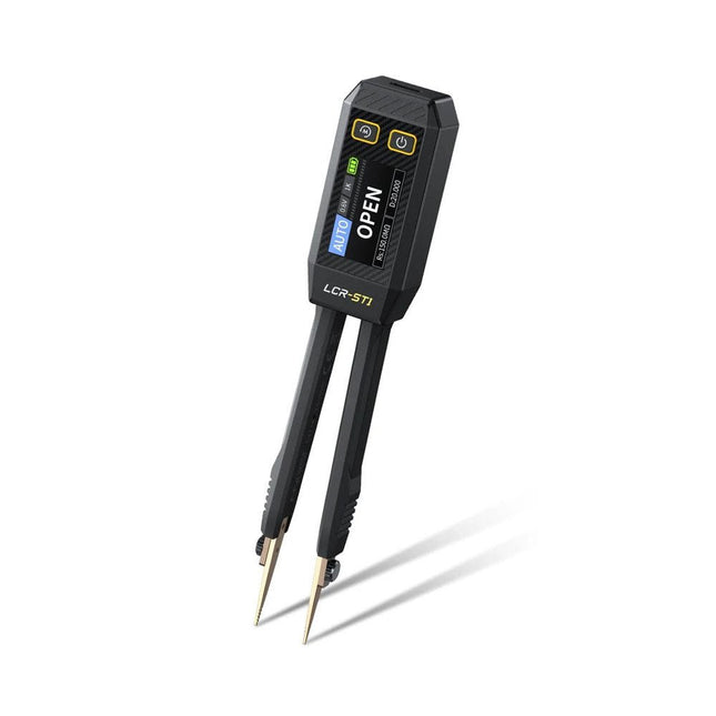
FNIRSI FNIRSI LCR-ST1 Smart SMD Tweezers (LCR/ESR Tester)
The FNIRSI LCR-ST1 is a compact, multifunctional, and smart LCR tester that supports automatic measurements of resistance, capacitance, inductance, diode testing, and continuity. Its 1.14-inch color display combined with a convenient magnetic adsorption function enhances ease of use, while the built-in 250 mAh lithium battery ensures long-lasting performance. The device supports three frequency ranges (100 Hz, 1 kHz and 10 kHz) and offers 0.3 V and 0.6 V RMS test levels for versatile testing applications. The unique tweezer-shaped design of the LCR-ST1 is ideal for delicate tasks in confined spaces and enables fast and accurate testing of electronic components. Its light weight and portable design make it an invaluable tool for both field and laboratory use. Whether you are an experienced engineer or just starting out in electronics, the LCR-ST1 delivers reliable and accurate measurement results, allowing you to complete your tasks with greater efficiency and precision. Features Offers 3 test frequencies (100 Hz, 1 kHz, 10 kHz) and 2 test voltage levels. Features automatic component identification for faster and more reliable measurements. High-resolution 1.14-inch color display for clear readouts. Supports automatic data recording and storage. The tweezer tips are made from gold-plated brass for enhanced durability and conductivity. Specifications Resistance Range 10 mΩ – 10 MΩ Capacitance Range 1 pF – 22 mF Inductance Range 1 μh – 10 H Diode On voltage 0.7 V Frequency Test 100 Hz, 1k Hz, 10 KHz Level Test 0.3 V, 0.6 V RMS Parameter Display ESR, D value, Q value, Z value, X value Display 1.14" HD color screen Charging Interface USB-C, 5 V/1 A Power Supply Built-in 250 mAh lithium battery Auto Recognition Measurement Yes Replaceable Tweezer Head Yes Auto Shutdown Yes Data Hold Yes History Record Connect to PC to view and export Dimensions 28 x 19 x 150 mm Weight 41 g Included 1x LCR-ST1 SMD Tweezers 2x Hook Tips 1x Magnetic Patch 1x USB cable 1x Tool bag 1x Manual Downloads Manual Firmware V1.6
€ 34,95
-
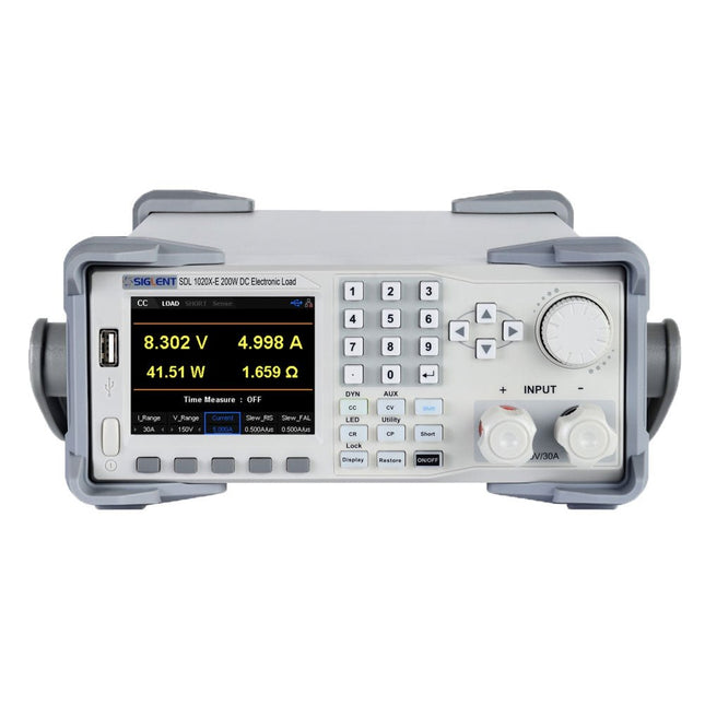
Siglent Siglent SDL1020X-E DC Electronic Load (200 W)
The Siglent SDL1020X-E DC Load leads with measurement resolution of 0.1 mV/0.1 mA and the base SDL1000X-E series resolution is 1 mV/1 mA and adjustable current rise times from 0.001 A/μs~2.5 A/μs. For remote communication and control, the SDL series includes S232/USB/LAN interface types. The SDL1020X-E delivers stability over a wide range of applications and can meet all kinds of testing requirements. including: Power, battery/handheld device design, industry, LED lighting, automotive electronics, and aerospace. Features SDL1020X-E (Single channel): DC 150 V/30 A, total power 200 W 4 static modes / Dynamic mode: CC/CV/CR/CP CC Dynamic mode: Continuous, pulsed, toggled CC Dynamic mode: 25 kHz, CP Dynamic mode: 12.5 kHz, CV Dynamic mode: 0.5 Hz Measuring speed of voltage and current: up to 500 kHz Adjustable current rise time range: 0.001 A/us~2.5 A/us Min. readback resolution: 0.1 mV, 0.1 mA Short-circuit, Battery test, CR-LED mode, and factory test functions 4-wire SENSE compensation mode function List function supports editing as many as 100 steps Program function supports 50 groups of steps OCP, OVP, OPP, OTP and LRV protection External analog control Voltage, Current monitoring via 0-10 V 3.5 inch TFT-LCD display, capable of displaying multiple parameters and states simultaneously Built-in RS232/USB/LAN communication interface, USB-GPIB module (optional) Waveform trend chart and easy-to-use file storage and call functions Includes PC software: Supports SCPI, LabView driver Included 1x Siglent SDL1020X-E DC Programmable Load 1x Quick start guide 1x Guarantee Card 1x Power Cord 1x USB Cable Downloads Datasheet Manual Programming Guide PC Software
€ 531,19
-
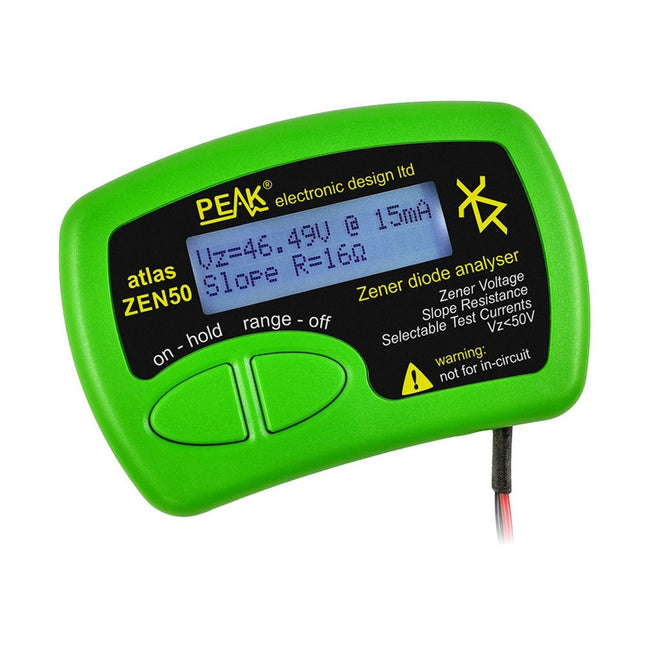
Peak Peak Atlas ZEN50 Zener Diode Analyzer
The Peak Atlas ZEN50 is ideal for testing Zener diodes (including avalanche diodes), transient suppressors, LEDs and LED strings. It generates constant current pulses (selectable from 2 mA, 5 mA, 10 mA and 15 mA) at voltages from 0 V to 50 V. So even high voltage Zeners or high voltage LED strings can be tested. Test currents are supplied in narrow pulses to ensure that the component under test remains at a constant temperature. The voltage of the part is displayed on the screen together with the test current and also a measure of the component's slope resistance (also known as dynamic impedance). Specifications Analyzer type Zeners, LEDs, TVS etc Test currents 2 mA, 5 mA, 10 mA, 15 mA Voltage range 0.00 to 50.00 V Slope resistance range 0 to 8000 Ohms Battery type Single AAA (supplied). Life typically 1400 ops Test method Triple pulse burst @ 10pps (typ) Test current duty cycle 3% Display type Alphanumeric LCD (with backlight) Included Peak Atlas ZEN50 Zener Diode Analyzer Fitted flexible test leads with gold plated crocs Comprehensive illustrated user guide AAA Alkaline battery Downloads Datasheet (EN) User Guide (EN) User Guide (FR) User Guide (DE) User Guide (IT)
€ 85,91
-
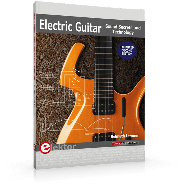
Elektor Publishing Electric Guitar (2nd Edition)
Sound Secrets and Technology What would today’s rock and pop music be without electric lead and bass guitars? These instruments have been setting the tone for more than sixty years. Their underlying sound is determined largely by their electrical components. But, how do they actually work? Almost no one is able to explain this to the true musician with no technical background. This book answers many questions simply, in an easily-understandable manner. For the interested musician (and others), this book unveils, in a simple and well-grounded way, what have, until now, been regarded as manufacturer secrets. The examination explores deep within the guitar, including pickups and electrical environment, so that guitar electronics are no longer considered highly secret. With a few deft interventions, many instruments can be rendered more versatile and made to sound a lot better – in the most cost-effective manner. The author is an experienced electronics professional and active musician. He has thoroughly tested everything described here, in practice.
€ 39,95
Members: € 35,96
-

Elektor Digital Elektor 05-06/2023 PDF (DE)
Diese Ausgabe steht allen GOLD- und GREEN-Mitgliedern auf der ElektorMagazine-Website zum Download bereit! Sie sind noch kein Mitglied? Hier klicken! Super-Servo-TesterBis zu vier Servos einzeln oder eingebaut testen Analoge Signale und der MikrocontrollerADCs, DACs, Strommessung und mehr embedded world 2023 Sub-Nyquist-Sampling in der PraxisHöhere Frequenzen mittels Unterabtastung sicher erfassen Hier Android-Smartphone, dort ESP32?Praxisprojekt mit der Android WiFi-API Aktives 1-kHz-Filter für VerzerrungsmessungenBessere Messungen durch Optimierung des Messsignals Aller Anfang...muss nicht schwer sein: Wir multivibrieren weiter! Projekt 2.0Korrekturen, Updates und Leserbriefe Das neue I3C-ProtokollWürdiger I2C-Nachfolger oder viel Rauch um Nichts? BlueRC: IR-Fernsteuerung mit Smartphone und ESP32Anpassungsfähig und universell Mikrocontroller-Dokumentationen verstehenTeil 2: Register und Blockschaltbilder Automatisierung der Prüf- und MesstechnikProgrammieren von Prüfgeräten, damit sie tun, was Sie wollen Infografik: Messen und Testen Überspannungsschutz für sicheren BetriebTransientenschutz für nicht-isolierte DC/DC-Leistungsmodule Mess- und Prüfgeräte von WihaInstallationstester und Messgeräte, auf die Sie sich verlassen können Automatisierung von Tests und Zusammenarbeit bei Testergebnissen Aus dem Leben gegriffenElektronik auf hohem Niveau EnergieloggerEnergie messen und aufzeichnen Aufgebaut: Das 4tronix M.A.R.S. Rover Kit Parkscheibe mit E-Paper DisplayEin innovativer digitaler Ersatz eCO2-Telegram-BotLuftqualitätsmessung mit Telegram-Anbindung Hinter den Kulissen von High-End-Audio im EigenbauElektor-Ingenieur Ton Giesberts im Interview über die hohe Kunst des Analogdesigns Das besondere ProjektEs gibt noch viel zu tun! RFID-Tag lesen und RFID-TürschlossProjektbeispiele aus dem Arduino-Experimentierpaket von Elektor Oszilloskop-Stromsonde für HFHochfrequenz-Strommessung leichtgemacht Nichts für Anfänger – Makerfabs 6 DOF Robot ArmMit Raspberry Pi Pico und MicroPython Generative KIWer hat das eigentlich gemacht? Hexadoku
€ 11,90
-

Elektor Labs Elektor Low-Noise Lab Power Supply
The Elektor Low-Noise Lab Power Supply is a fully analogue, adjustable, medium-power symmetrical bench supply that contains no switching or digital components. It provides an output voltage adjustable between 0 V and ±22 V, and an output current adjustable from 0 A to 1 A. Because it avoids any form of switching circuitry, the design delivers extremely low noise. To display both output voltages and currents, four miniature moving-coil panel meters are used. Most modern laboratory power supplies and AC adapters employ switch-mode techniques. Even the best examples inevitably exhibit high-frequency ripple and other switching artefacts on their output, which can interfere with the testing of sensitive analogue circuits and disturb low-level measurements. To overcome this, the concept here is a completely analogue power supply. Although less efficient than its switch-mode counterparts, the reduced efficiency is of little importance for test-bench use and ensures cleaner, more reliable measurement results. Because many analogue circuits require a symmetrical supply, this design delivers positive and negative output voltages of equal magnitude. A small amount of adjustment is available to compensate for any imbalance. Naturally, a variable current-limit function is also included. The kit includes the components required to build the power supply, except for the transformers. Specifications Output Voltage 0…+22 V, 0, −22 V Output Current 0…+1 A, 0…−1 A Noise −85 dBV, (at 0.95 A/20 V, B = 22 kHz) −84 dBV (at 0.95 A/20 V, B > 500 kHz) Ripple 50 µVRMS (at 950 mA/20 V, B = 22 kHz, mainly 100 Hz component) Included 3x PCBs: Regulator (PCB-1), Mains Filter (PCB-2) and Transformer (PCB-3) All the components except the AC transformers 4x moving-coil meters Additional parts for wiring (wires, banana sockets, IEC Power entry module, etc.) Not included The three AC transformers An enclosure Parts List For the Regulator PCB (240386-1) Resistors (250 mW, 1%) R1 = 12 Ω R2, R8, R37, R62 = 1 MΩ R3, R7, R10, R13, R17, R20, R22, R30, R35, R42, R45, R47, R55, R60 = 100 Ω, 600 mW R4, R5 = 4.7 kΩ R6 = 100 kΩ R9, R12, R14, R36, R38, R39, R61, R63, R66, R72, R78, R79 = 10.0 kΩ, 600 mW R11 = 9.76 kΩ, 600 mW R15, R40 = 44.2 kΩ, 600 mW R16, R41, R77 = 1 kΩ R18, R43 = 1.5 kΩ, 1 W, 5% R19, R44 = 470 Ω, 1 W, 5% R21, R46 = 330 Ω, 600 mW R23, R24, R48, R49 = 1.0 Ω, 1 W R25, R50 = 1 kΩ, 1 W, 5% R26, R28, R51, R53 = 1.000 kΩ 0.1%, 15 ppm/C R27, R29, R52, R54 = 10.00 kΩ 0.1%, 15 ppm/C R31, R56 = 1.2 kΩ, 1 W, 5% R32, R57 = 47 kΩ R33, R58 = 270 Ω R34, R59 = 27 kΩ R64, R69 = 12.0 kΩ R65 = 3.0 kΩ, 600 mW R67, R80 = 470 Ω, 600 mW R68, R70 = 6.8 kΩ, 600 mW R71 = 30.0 kΩ,, 600 mW R73, R74, R75, R76 = 10 MΩ P1, P2, P3 = 10 kΩ, 200 mW, 20%, potentiometer, 1 turns, single, lin., panel mount P4, P5 = 500 Ω, 500 mW, 10%, trimmer, 25 turns, 3296Y-1-501LF Bourns P6, P7 = 10 kΩ, 500 mW, 10%, trimmer, 25 turns, 3296Y-1-501LF Bourns Capacitors C1 = 100 nF, 50 V, 10%, ceramic X7R, LS 5 mm C2, C3, C6, C7, C30 = 10 µF, 63V, 20%, LS 2.5 mm, 3000hours@105°C C4, C5, C8, C9, C13, C14, C18, C19, C23, C24, C28, C29, C31, C32, C38, C39 = 100 nF, 250 V, 10%, PET, LS 7.5 mm C10, C20 = 47 nF, 100 V, 5%, PET, LS 5 mm C11, C21 = 10 nF, 100 V, 5%, PET, LS 5 mm C12, C22 = 220 µF, 35 V, 20%, 0.024 Ω, LS2.5/3.5 mm, Ir 3.4 A, 2000hours@125°C, polymer C15, C25 = 120 µF, 50 V, 20%, ESR 0.02 Ω, Diam. 10 mm max., LS 5 mm C16, C26 = 15 nF, 100 V, 5%, PET, LS 5 mm C17, C27 = 47 nF, 100 V, 5%, PET, LS 5 mm C33, C34 = 22 µF, 50 V, 20%, LS 2 mm, 10000 hours @ 105°C C35, C36, C44, C45 = 1 µF, 100 V, 10%, LS 5 mm, ceramic X7R C37 = 100 uF, 50 V, 20%. LS 3.5 mm C40, C41, C42, C43, C46, C47, C48, C49 = 1000 µF, 50 V, 20%, LS 5/7.5 mm, Ir 3.32 A, 10000hours@105°C, D 16 mm C50, C51, C52, C53 = 47 nF, 100 V, 10%, ceramic X7R, LS 5 mm Inductors L1, L2 = 4.7 µH, 3.2 A, 0.033 Ω, LS 5 mm, RLB0914-4R7ML Bourns L3 = Commom mode choke, 14.5 mH, 3 A, SSRH24NH-30145 Kemet Semiconductors D1, D2, D3, D4, D5, D9, D10, D11, D15 = BAT85, DO-34 D6, D7, D12, D13 = SR560, DO-201AD D8, D14, D16 = 1N4148, DO-35 D17 = Zenerdiode, 5.6 V, 0.5 W, DO-41 D18, D19 = 1N4004, DO-41 D20, D21 D22, D23 = V30100CI-M3/P, dual common cathode, TO-220 D24 = Zener diode, 30 V, 1 W, DO-41 LED1, LED2 = LED, red, T-1 (3 mm) LED3, LED4 = LED, green, T-1 (3 mm) TVS1, TVS2 = BZW50-33B, R6 T1, T2, T4 = BC337.25, TO-92 T3 = NJW0302G, TO-3P T5, T6, T8 = BC327.25, TO-92 T7 = NJW0281G, TO-3P T9 = BD139, TO-126 (SOT-32) IC1 = LM334Z, TO-92 IC2 = LM4040AIZ-5.0/NOPB, TO-92 (TO-226AA-3) IC3, IC4 = OPA2992IDR, SOIC-8 IC5, IC6 = OPA4992IDR, SOIC-14 IC7 = OPA992IDBVR, SOT-23-5 IC8 = LM339N, DIP-14 IC9 = LM317, TO-220 IC10 = LM337, TO-220 Others F1, F2 = 5×20 mm fuse, 1.6 A, fast acting HS1, HS2 = Heatsink MC33271 (for T3/T7), 2.7°C/W, PCB mount, height 63.5 mm K1, K4 = 3-way screw terminal block, LS 3.5 mm, max. 1.5 mm² K2, K3 = 3-way screw terminal block, LS 3.5 mm, max. 1 mm² M1, M3 = Moving coil meter, Range 30 V, type 91C4, 45×45 mm M2, M4 = Moving coil meter, Range 1 A, type 91C4, 45×45 mm² RE1 = Relay DPDT,5V, UA2-5NU Miscellaneous 3× 3-way screw terminal block, LS 3.5 mm, max. 1 mm² (for P1, P2, P3) 4× Pin header, 1×2, vertical, pitch 2.54 mm (for LED1, LED2, LED3, LED4) 4× Pin socket, 1×2, vertical. pitch 2.54 mm (for LED1, LED2, LED3, LED4) 2× Heatsink FK222SA220, 20°C/W, PCB mount (for IC9 & IC10) 2× Mica thermal pad for TO-220, 12×18×0.05 mm (for IC9 & IC10) 2× Insulating bushing IB 6, TO-220 (for IC9 & IC10) 2× Ceramic thermal pad, 23×20×2 mm (for T3 & T7) 2× PCB Fuse Holder, for 5×20 mm fuse, 10 A (for F1, F2) 2× Cover for PCB Fuse Holder, transparent (for F1, F2) 2× 2-way screw terminal block, LS 3.5 mm, max. 1 mm² (for M1 & M3) 2× 2-way screw terminal block, LS 3.5 mm, max. 1.5 mm² (for M2 & M4) 8× M3 solder lug, thickness 0.35 mm (for M1…M4) M4 solder lug, thickness 0.35 mm (to connect 4 mm banana connectors) Screened cable, 1 pair, 2×24 AWG/0.22 mm², 1 m (for P1, P2 & P3) IC socket, DIP, 14 contacts (for IC8) M3 washer, plain, steel M3 screw, 16 mm, steel, pan head M3 nut M3 spring washer 50 mm M3 standoff, steel, male-female 12 mm M3 standoff, steel, male-female 10 mm M3 standoff, steel, male-female M3 screw, 8 mm, steel, pan head For the Mains Fiter PCB (240386-2) Resistor R1 = 220 kΩ, 1 W, 500 V, 5% Capacitors C1, C2 = 470 nF, 305 VAC, Class X2, 11 × 27 mm max., LS 15/22.5 mm C3, C4, C5, C6 = 2.2 nF, 300 VAC, Class Y2, 13 × 4 mm, LS 10 mm, PP Inductors L1, L2 = Common-mode choke, 6.8 mH, 1.7 A, TDK B82732R2172B030 Semiconductor MOV1 = TVS varistor, 300 VAC, S14K300 (230 VAC, B72214S0301K101) and SK14K150 (150 VAC, B72214S0151K101) Others K1, K2 = 3-way screw terminal block, LS 7.62 mm F1 = Time-delay fuse, 0.5 A (230 VAC) or 1 A (115 VAC) Miscellaneous 1× Fuse holder, 5×20 mm, 10 A, 500 VAC 1× Transparent fuse cover 4× 10 mm M3 standoff, steel, male–female 4× M3 screw, 8 mm, steel, pan head 4× M3 nut For the Transformer PCB (240386-3) Resistors R1, R2 = 2.7 kΩ, 600 mW, 1% R3 = 10.0 kΩ, 600 mW, 1% Capacitor C1 = 220 µF, 50 V, 20%, Ø10 mm, LS 5 mm, 4000 h @ 105°C Transformers (not included in this kit!) TR1, TR2, TR3 = 2×7 V, 25 VA, PCB-mounted toroid, 70060K Talema Semiconductors D1–D4 = 1N4148, DO-35 D5, D6 = 1N4004, DO-41 D7 = Zener 5.6 V, 1.3 W, DO-41 LED1 = LED, red, T-1 (3 mm) IC1, IC2 = MOC8021M, CTR ≥ 1000%, DIP-6 Others F1, F2, F3 = 160 mA time-delay fuse (230 VAC) or 315 mA time-delay fuse (115 VAC) K1 = 2-way screw terminal block, LS 7.62 mm K2 = 3-way screw terminal block, LS 3.5 mm, max 1.5 mm² K3, K4 = 3-way screw terminal block, LS 3.5 mm, max 1 mm² RE1, RE2 = Relay DPDT, 5 A/250 VAC / 24 VDC Miscellaneaous 1× Pin header 1×2, pitch 2.54 mm + matching socket for LED1 3× Fuse holder 5 × 20 mm, 10 A, 500 VAC + transparent cover 3× M4 screw, 8 mm, pan head + washer for TR1-TR3 8× M3 screw, 8 mm, pan head + nut + washer 8× 10 mm M3 standoff, steel, male–female 2× IC socket, DIP-6 for IC1 & IC2 Additional Parts 1 m red insulated wire, stranded, 1.5 mm² 0.5 m blue insulated wire, stranded, 1.5 mm² 0.5 m black insulated wire, stranded, 1.5 mm², 0.5 m 2 m red insulated wire, stranded, D 0.56 mm (0.25 mm²) 2 m black insulated wire, stranded, D 0.56 mm (0.25 mm²) 0.5 m Multicore Cable, Flexible, 3 Core, 0.75 mm² (24 x 0.2 mm) Red banana socket Black banana socket Blue banana socket Green banana socket IEC Power Entry Module with switch, IEC C14 3 crimp terminals, FASTON, 4.75 x 0.81 mm 3 knobs Links Elektor Labs JumpStarter Page Article (Part 1) Article (Part 2)
€ 249,00
Best Price
-

Elektor Digital Elektor May/June 2026 (PDF) EN
Elektor GREEN and GOLD members can download their digital edition here. Not a member yet? Click here. PbMonitor v2.0 UpdateBattery Monitoring with Improved Analog Design Audio Latency MeasurementA Standalone Tool for Evaluating Errors and Latency in Audio Transmission Square Wave vs. Bode PlotChecking the Performances of an Audio Device embedded world 2026 Clever Coding with AIAI in Software Development for Electronics Engineers QA403 Audio AnalyzerAffordable Precision for Audio Professionals and Hobbyists EasyGimbalAutonomous Camera Tracking with AI, Stepper and Servo Motors Sigfox Breakout Board (2)Sending Messages Circuit ProtectionControlling Overvoltages with TVS Diodes Emerging Battery Testing ApproachesA New Era of Diagnostics AudiotronicsA First Preamplifier CANopenTermAn Open-Source Tool That Brings CAN to Makers and Engineers Alike Stabilization of Operational AmplifiersAvoiding Feedback Instability Err-lectronicsCorrections, Updates, and Readers’ Letters Signal ConditioningTips and Tricks to Fit Voltage Ranges TDR Attachment for OscilloscopesLength, Short Circuit, Mismatch: Measure Cables Using Reflections! From Life's ExperienceLED It Be Speaker Oscillator and Resonance TesterA Fully Experimental Project for Your Speakers Elektor Community Perspectives on Test and Measurement ESP32 Audio Transceiver Board (Part 5)Audio Processing and Remote Control 2026: An AI OdysseyAI Has a Context Problem Battery Storage for Balcony Power PlantsSmall Batteries, Big Impact
€ 9,50


