High-Performance LoRa Communication Device
The Elecrow ThinkNode M5 is a compact, portable LoRa communication device designed for off-grid messaging, location sharing, and outdoor use. Powered by an ESP32-S3 processor and an SX1262 LoRa chip, it comes pre-installed with Meshtastic firmware and can be configured conveniently via Bluetooth using the official Meshtastic app.
The integrated multi-GNSS module supports GPS, GLONASS, BeiDou, and QZSS for reliable positioning and location sharing. Messages and device information are displayed on the energy-efficient 1.54-inch e-paper screen, while the built-in 1,200 mAh rechargeable battery enables extended mobile operation.
With its integrated LoRa antenna, compact housing, RTC, and support for both Meshtastic and MeshCore firmware, the ThinkNode M5 is a practical communication solution for hiking, camping, remote locations, and emergency situations where conventional mobile networks are unavailable.
Features
LoRa communication
Multi-GNSS positioning
1,200 mAh rechargeable battery
1.54-inch e-paper display
Built-in RTC
Compatible with MeshCore
Compatible with Meshtastic
Specifications
Main Processor (ESP32-S3)
CPU/SoC
Xtensa 32-bit LX7 dual-core processor, clocked at up to 240 MHz
System Memory
512 KB SRAM, 8 MB PSRAM
Storage
4 MB Flash, 384 KB ROM
Firmware
Meshtastic firmware is fully compatible, and the signal is transmitted in LoRa mode
EPD (Electronic Paper Display)
Display Size
1.54 inch EPD (monochrome Ink screen)
Display Materials
E-lnk (Electronic Ink)
Resolution
200 x 200
Driver Chip
SSD1681 (via SPI or I²C interface)
Global Fresh Time
2s
Wireless Communication
Bluetooth
Bluetooth Low Energy and Bluetooth 5.0 (phone configuration)
LoRa
SX1262 LoRa Module, EU 868 MHz(external antenna)
Hardware
Interfaces
USB-C, RP-SMA
Function
GPS Location (GPS, GLONASS, BeiDou, QZSS), EPD Display, RTC, USB 2.0, PMU power management (built-in 1200 mAh lithium battery), buzzer, etc.
Button
Knob Switch, Function Button, Page Turn Button, GPS Switch, Reset Button
LED Indicator
Power supply, GPS/LoRa indication
Others
Power Input
5 V/1 A, supports USB or lithium battery power supply
Power consumption
The maximum working current is about 340 mA (CPU + LoRa module), and the low power consumption is about 34 uA
Operating Temperature
-10~50°C
Storage Temperature
-20~60°C
Relative humidity
10-95%, @ 40°C (non-condensing)
Enclosure
ABS Plastic
Dimensions
82 x 51.6 x 26.3 mm
Weight
81 g
Included
1x Elecrow ThinkNode M5
1x LoRa antenna
1x USB-C cable
1x Manual
Downloads
Manual
DEAL: Order the HackRF Pro now and get the e-book "SDR with HackRF One & HackRF Pro" worth €20 for FREE!
HackRF Pro is latest Software Defined Radio (SDR) from Great Scott Gadgets and the powerful successor to the legendary HackRF One. With a frequency range from 100 kHz to 6 GHz, it covers an enormous spectrum for transmitting and receiving radio signals.
Designed as an open-source hardware platform, the HackRF Pro is the ideal tool for analyzing and developing modern wireless technologies. It can be used flexibly as a USB peripheral or programmed for standalone operation.
Specifications
Frequency: 100 kHz to 6 GHz
Adjustable from 0 Hz to 7.1 GHz
Half-duplex transceiver
Up to 20 million samples per second
8-bit quadrature samples (8-bit I and 8-bit Q)
Compatible with GNU Radio, SDR#, and more
Software-configurable RX and TX gain and baseband filter
Software-controlled RF port power (50 mA at 3.3 V)
SMA RF connector
SMA clock input and output for synchronization and triggering
Convenient buttons for programming
Internal pin headers for expansion
High-Speed USB 2.0 with USB-C connector
USB-powered
Open source hardware
Compared to its predecessor, HackRF Pro offers a variety of new features, including:
Wider operating frequency range
Improved RF performance with flatter frequency response
USB-C connector
Built-in TCXO crystal oscillator for superior timing stability
Logic upgrade from a CPLD to a power-efficient FPGA
Elimination of the DC spike
Extended-precision mode with 16-bit samples for low sample rates (typical ENOB: 9-11)
Half-precision mode with 4-bit samples at up to 40 Msps
More RAM and flash memory for custom firmware
Installed shielding around the radio section
Trigger input and output accessible through clock connectors
Cutout in the PCB provides space for future add-ons
Improved power management
Enhanced RF port protection
Facility to hardware-disable transmit mode
Full Compatibility: Thanks to its proven architecture, existing software for the HackRF One can also be used directly with the HackRF Pro. The HackRF Pro offers seamless backward compatibility while significantly increasing performance.
Note: An antenna is not included. We recommend the ANT500 for the best experience.
Included
HackRF Pro SDR with plastic enclosure
E-book: SDR with HackRF One & HackRF Pro (normal price: €20)
Downloads
Documentation
GitHub
Diese Ausgabe steht allen GOLD- und GREEN-Mitgliedern auf der ElektorMagazine-Website zum Download bereit!
Sie sind noch kein Mitglied? Hier klicken!
ESP32-Audio-Transceiver-Board (Teil 2)Drahtlose Audioübertragung
Induktiver AM-SenderPIO des Pico in einem Arduino-Sketch
Navigieren durch drahtlose ProtokolleEin technischer Leitfaden
Satellitenverfolgung mit LoRaDas TinyGS-Netzwerk: Raumfahrtdaten gelangen zur Erde
4G-kompatible SMS-FernbedienungSteuern Sie Ihr Zuhause per Telefon aus der Ferne
Hochgeschwindigkeits-TastkopfHochohmige Eingänge für Signale bis 200 MHz
Aus dem Leben gegriffenKafka
KrakenSDREin phasenkohärenter SDR-Empfänger
Geschwindigkeitstests mit dem RP2350Lohnt sich der Umstieg von Raspberry Pi Pico 1 auf Version 2?
Kontaktlose E-Feld-Messungen (2)Ein Laser-Vibrometer zur Erfassung der Membranschwingungen
Quarze und OszillatorenQuarzgenauigkeit durch die Kondensatorwahl verbessern
Aller Anfang ...... ist gar nicht schwer: Spezielle Audio-ICs
Einstieg ins Programmieren von Selbstbauprojekten
SPECTRAN® V6 MobileModular konfigurierbarer Echtzeit-Spektrum-Analyzer für zuverlässige Messungen in allen Frequenzbereichen
Die Zukunft der KI wird in Silizium geschmiedetEin Interview mit Anastasiia Nosova
Autonomer Sensorknoten v2.0 (Systemarchitektur)Solarbetriebene Sensorplattform mit integriertem GPS, LoRaWAN und weiteren Funktionen
Präzise PositionsbestimmungBluetooth Channel Sounding ausprobiert
Die Zukunft der Wireless-KommunikationDie ultradünnen Festkörperbatterien von BTRY
Testgetriebene Programmierung in der Firmware-Entwicklung
Handy-gesteuertes ModellautoWLAN + ESP32 + Smartphone = Fernsteuerung
2025: Eine KI-OdysseeKI-Denkmodelle: die Gedankenketten-Revolution
Solarladeregler mit MPP-TrackingTeil 3: Software und Inbetriebnahme
Web-Streaming-Kamera mit Raspberry Pi ZeroVerwendung des ZeroTier-VPN
Build Your Own Vintage Radio Broadcaster
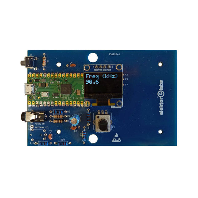
The Elektor AM Transmitter Kit allows streaming audio to vintage AM radio receivers. Based on a Raspberry Pi Pico microcontroller module, the AM Transmitter can transmit on 32 frequencies in the AM band, from 500 kHz up to 1.6 MHz in 32 steps of approx. 35 kHz.
The frequency is selected with a potentiometer and shown on a 0.96" OLED display. A pushbutton allows toggles the transmitting mode between On and Off. The range of the transmitter depends on the antenna. The onboard antenna provides a range of a few centimeters, requiring the AM Transmitter to be placed close to or inside the radio. An external loop antenna (not included) can be connected to increase the range.
The Elektor AM Transmitter Kit comes as a kit of parts that you must solder to the board yourself.
Features
The board is compatible with a Hammond 1593N enclosure (not included).A 5 VDC power supply with micro-USB connector (e.g., an old phone charger) is needed to power the kit (not included). Current consumption is 100 mA.
The Arduino software (requiring Earle Philhower’s RP2040 Boards Package) for the Elektor AM Transmitter Kit plus more information is available at the Elektor Labs page of this project.
Component List
Resistors
R1, R4 = 100 Ω
R2, R3, R8 = 10 kΩ
R5, R6, R9, R10, R11 = 1 kΩ
R7 = optional (not included)
P1 = potentiometer 100 kΩ, linear
Capacitors
C1 = 22 µF 16V
C2, C4 = 10 nF
C3 = 150 pF
Miscellaneous
K1 = 4×1 pin socket
K2, K3 = 3.5 mm socket
Raspberry Pi Pico
pushbutton, angle mount
0.96" monochrome I²C OLED display
PCB 150292-1
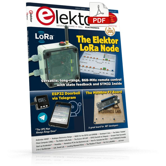
The Elektor LoRa NodeVersatile, long-range, 868-MHz remote control with state feedback and STM32 Inside
InteractiveCorrections & Updates || Questions & Answers
Analogue Electronics DesignCase Study #1 — Section 2: Preamplifier optimized for MEMS microphone
My IoT Button: A Button for the WebPart 1: IoT architecture
BASIC for the ESP32 and ESP8266Programming with Annex WiFi RDS
ESP32 Doorbell via Telegram“The UPS Man Always Rings Once”
Small Circuits RevivalCapita Selecta from the Elektor Project Suggestions Box
My First LoRaWANWith Blue Pill, LoRa Breakout Board and The Things Network
Elektor Connexions 2003EL
“A Strong Supporter of Open Internet”Interview with Wienke Giezeman, Initiator of The Things Network
The Meadow F7 BoardA great board for .NET developers
Practical ESP32 Multitasking (2)Task priorities
Sigfox and the IoT (3)First steps on the network
Raspberry Pi Bash Command Cheat Sheet
Europe's Most Successful Start-up Accelerator?HighTechXL, Eindhoven, The Netherlands
Review: The Enviro+ RPi-HATMeasure air quality with a Raspberry Pi and the Enviro+ HAT
Steeped in Electronicsordering components from Ukraine and Russia
Review: Andonstar AD407Better than its predecessor?
Lab, Sweet LabA glimpse of The Holy Place — no unauthorized entry.
Optical Probe for OscilloscopesMeasure brightness fluctuations of lighting systems
The 'TABULA' Project - An UpdateTangibles with user feedback
How-To Calculate the Prospective Short-Circuit Current or PSCCand choose the proper circuit breaker
TMS1000 Series Microcontrollers
Peculiar Parts, the series
Starting Out in Electronics (2)
Easier than imagined!
Developer's ZoneTips & Tricks, Best Practices and Other Useful Information
Locating Wayward Wires
Track and trace concealed and defective cables with ease and certainty
Review: Joy-IT DMSO2D72 Portable 3-in-1 Oscilloscope
Homebrew PC for the Electronics LabTips on Component Choice and Construction
The Elektor ‘Intelekt’ Chess Computer (1981)Tiny Chess 86 ported to the Intel 8088
Beyond ElectronicsPCB Art - Pushing the Limits of Industrial Manufacturing
Buch: Logic Analyzer im Einsatz
Schritt-für-Schritt-Anleitungen führen Sie in die Analyse moderner Protokolle von I²C, SPI, UART, RS-232, NeoPixel, WS28xx, HD44780 und 1-Wire ein. Anhand von zahlreichen Experimentierschaltungen mit dem Raspberry Pi Pico, Arduino Uno und dem Bus Pirate üben Sie die praxisnahe Anwendung gängiger USB-Logikanalysatoren ein.
Alle in diesem Buch vorgestellten Experimentierschaltungen wurden vollständig getestet und sind funktionsfähig. Die notwendigen Programmlistings sind enthalten, es sind keine besonderen Programmier- oder Elektronikkenntnisse für diese Schaltungen notwendig. Es werden die Programmiersprachen MicroPython und C mit den Entwicklungsumgebungen Thonny und Arduino IDE eingesetzt.
Dieses Buch verwendet mehrere Modelle flexibler und weit verbreiteter USB-Logikanalysatoren und zeigt die Stärken und Schwächen jeder Preisklasse. Sie werden kennenlernen, welche Kriterien für Ihre Arbeit wichtig sind und in der Lage sein, das für Sie passende Gerät zu finden.
Egal ob Arduino, Raspberry Pi oder Raspberry Pi Pico: Die abgebildeten Beispielschaltungen ermöglichen einen schnellen Start in die Protokollanalyse und können auch als Grundlage für eigene weitere Experimente dienen.
Sie werden alle wichtigen Begriffe und Zusammenhänge kennenlernen, eigene Experimente durchführen, selbstständig Protokolle analysieren und nach der Lektüre dieses Buches – im Bereich der digitalen Signale und Protokolle – ein umfassendes Wissen aufgebaut haben.
USB Logic Analyzer (8 Kanäle, 24 MHz)
Dieser USB Logic Analyzer ist ein 8-Kanal-Logikanalysator, bei dem jeder Eingang doppelt für die analoge Datenaufzeichnung dient. Es eignet sich perfekt zum Debuggen und Analysieren von Signalen wie I²C, UART, SPI, CAN und 1-Wire. Dabei wird ein digitaler Eingang, der mit einem zu testenden Gerät (DUT) verbunden ist, mit einer hohen Abtastrate abgetastet. Die Verbindung zum PC erfolgt via USB.
Technische Daten
Kanäle
8 digitale Kanäle
Maximale Abtastrate
24 MHz
Maximale Eingangsspannung
0 V ~ 5 V
Betriebstemperatur
0°C ~ 70°C
Eingangsimpedanz
1 MΩ || 10 pF
Unterstützte Protokolle
I²C, SPI, UART, CAN, 1-Wire etc.
PC-Verbindung
USB
Abmessungen
55 x 28 x 14 mm
Downloads
Software
Dieses Bundle enthält:
Buch: Logic Analyzer im Einsatz (Einzelpreis: 40 €)
USB Logic Analyzer (8 Kanäle, 24 MHz) (Einzelpreis: 20 €)
USB-Kabel
Jumper Wire Ribbon Kabel
The Siglent SSA3015X Plus spectrum analyzer is a powerful and flexible tool for RF signal and network analysis. With a frequency range of 1.5 GHz, the analyzer delivers reliable automatic measurements and multiple modes of operation: spectrum analyzer the base, optional functions include RF power measurement, vector signal modulation analysis, reflection measurement, and EMI test.
Applications include broadcast monitoring/evaluation, site surveying, S-parameter measurement, analog/digital modulation analysis, EMI pre-compliance test, research and development, education, production, and maintenance.
Features
Spectrum Analyzer Frequency Range from 9 kHz to 1.5 GHz
–156 dBm/Hz Displayed Average Noise Level (Typ.)
–99 dBc/Hz. @ 10 kHz Offset Phase Noise (1 GHz, Typ.)
Level Measurement Uncertainty <1.2 dB (Typ.)
1 Hz Minimum Resolution Bandwidth (RBW)
Preamplifier (Std.)
Tracking Generator (incl. free of charge)
Analog and Digital Signal Modulation Analysis Mode (opt.)
Reflection Measurement Kit (opt.)
EMI Filter and Quasi-Peak Detector Kit (opt.)
Advanced Measurement Kit (opt.)
10.1-inch Multi-Touch Screen , Mouse and Keyboard supported
Web Browser Remote Control on PC and Mobile Terminals and File Operation
Specifications
SSA3015X Plus
SSA3021X Plus
SSA3032X Plus
SSA3075X Plus
Frequency Range
9 kHz ~ 1.5 GHz
9 kHz ~ 2.1 GHz
9 kHz ~ 3.2 GHz
9 kHz ~ 7.5 GHz
Resolution Bandwidth
1 Hz ~ 1 MHz
1 Hz ~ 1 MHz
1 Hz ~ 1 MHz
1 Hz ~ 3 MHz
Phase Noise
<–99 dBc/Hz
<–98 dBc/Hz
<–98 dBc/Hz
<–98 dBc/Hz
Total Amplitude Accuracy
<1.2 dB
<0.7 dB
<0.7 dB
<0.7 dB
Display Average Noise Level
–156 dBm/Hz
–161 dBm/Hz
–161 dBm/Hz
–165 dBm/Hz
Included
Siglent SSA3015X Plus spectrum analyzer
USB cable
Power cord
Quick start guide
Downloads
Datasheet
Manual
Documentation
Firmware
Elektor GREEN en GOLD leden kunnen deze uitgave hier downloaden.
Nog geen lid? Klik hier om een lidmaatschap af te sluiten.
ESP32 Audio Transceiver Board (Deel 2)Draadloze audio-overdracht
Inductieve AM-zenderGebruikt Pico's PIO in een Arduino-sketch
Navigeren door draadloze protocollen navigerenEen technische gids
Satelliettracking met behulp van LoRaHet TinyGS-netwerk brengt gegevens uit de ruimte naar de aarde.
4G-Compatibele SMS afstandsbedieningBedien je apparatuur op afstand
Hogesnelheids-probeIngangen met hoge impedantie voor signalen tot 200 MHz
Uit het leven gegrepenKafka
KrakenSDR
Prestatietests met de RP2350Is een upgrade van Raspberry Pi Pico 1 naar versie 2 de moeite waard?
Contactloze E-veldmetingen (2)Een laservibrometer voor het beoordelen van de trillingen van het membraan
Kristallen en oscillatorenVerbetering van de kristalnauwkeurigheid door gerichte keuze van condensatoren
Alle begin......gaat audio!
Zelf firmware coderen voor embedded projecten
SPECTRAN® V6 MobileModulaire, configureerbare realtime-spectrumanalyzer voor betrouwbare metingen over alle frequentiebereiken
De toekomst van AI wordt gesmeed in siliciumEen interview met Anastasiia Nosova
Autonome Sensor-Node v2.0 (Systeemarchitectuur)Zonne-energieplatform met geïntegreerde GPS, LoRaWAN en meer
Precieze positioneringBluetooth channel sounding getest
Testgestuurd ontwikkelen bij het schrijven van firmware
Telefoon gestuurde modelautoWi-Fi + ESP32 + Smartphone = Afstandsbediening
2025: Een AI-odysseeAI-redeneermodellen: De gedachtegang-revolutie
Zonne-laadregelaar met MPP-tracking (3)Software en Inbedrijfstelling
Raspberry Pi Zero Web Streaming CameraDe ZeroTier VPN gebruiken
Beste soldeerder van de Beneluxvakmanschap in de schijnwerpers
Seminaroverzicht Electronics & ApplicationsLeer, ontdek en netwerk op E&A 2025
Eurocircuits at E&A 2025
E&A gadget 2025: racen over de beursvloer met slimme printplaat op wielenVijf vragen aan Casper van Doorne, ontwerper van de beursgadget
Beursgadget E&A bekendontwerp en bestuur je eigen raceauto
Vakbeurs E&A is het elektronicaparadijs van de Benelux“Techneuten blijven kinderen”
Rohde & SchwarzPioneering Innovation in Test & Measurement
Diederik Jekel opent Electronics & Applications
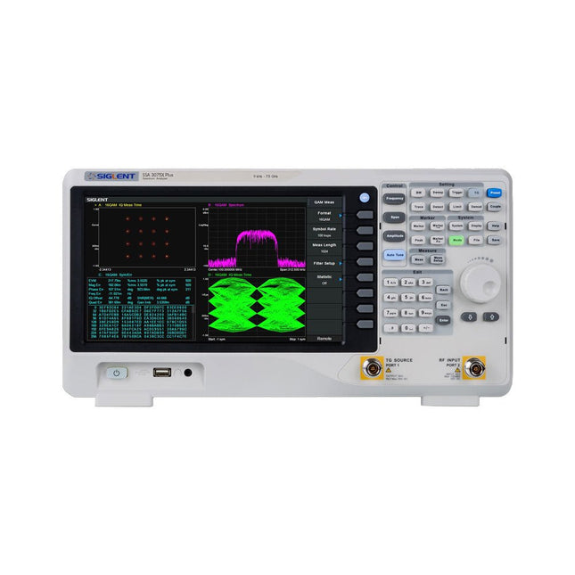
The Siglent SSA3075X Plus spectrum analyzer is a powerful and flexible tool for RF signal and network analysis. With a frequency range of 7.5 GHz, the analyzer delivers reliable automatic measurements and multiple modes of operation: spectrum analyzer the base, optional functions include RF power measurement, vector signal modulation analysis, reflection measurement, and EMI test.
Applications include broadcast monitoring/evaluation, site surveying, S-parameter measurement, analog/digital modulation analysis, EMI pre-compliance test, research and development, education, production, and maintenance.
Features
Spectrum Analyzer Frequency Range from 9 kHz to 7.5 GHz
–165 dBm/Hz Displayed Average Noise Level (Typ.)
–98 dBc/Hz. @ 10 kHz Offset Phase Noise (1 GHz, Typ.)
Level Measurement Uncertainty <0.7 dB (Typ.)
1 Hz Minimum Resolution Bandwidth (RBW)
Preamplifier (Std.)
Tracking Generator (incl. free of charge)
Analog and Digital Signal Modulation Analysis Mode (opt.)
Reflection Measurement Kit (opt.)
EMI Filter and Quasi-Peak Detector Kit (opt.)
Advanced Measurement Kit (opt.)
10.1-inch Multi-Touch Screen , Mouse and Keyboard supported
Web Browser Remote Control on PC and Mobile Terminals and File Operation
Specifications
SSA3015X Plus
SSA3021X Plus
SSA3032X Plus
SSA3075X Plus
Frequency Range
9 kHz ~ 1.5 GHz
9 kHz ~ 2.1 GHz
9 kHz ~ 3.2 GHz
9 kHz ~ 7.5 GHz
Resolution Bandwidth
1 Hz ~ 1 MHz
1 Hz ~ 1 MHz
1 Hz ~ 1 MHz
1 Hz ~ 3 MHz
Phase Noise
<–99 dBc/Hz
<–98 dBc/Hz
<–98 dBc/Hz
<–98 dBc/Hz
Total Amplitude Accuracy
<1.2 dB
<0.7 dB
<0.7 dB
<0.7 dB
Display Average Noise Level
–156 dBm/Hz
–161 dBm/Hz
–161 dBm/Hz
–165 dBm/Hz
Included
Siglent SSA3075X Plus spectrum analyzer
USB cable
Power cord
Quick start guide
Downloads
Datasheet
Manual
Documentation
Firmware
Diese Ausgabe steht allen GOLD- und GREEN-Mitgliedern auf der ElektorMagazine-Website zum Download bereit!
Sie sind noch kein Mitglied? Hier klicken!
Ein autonomer SensorknotenLoRa-Datenübertragung und Solar-Stromversorgung
Elektor eXpansion Board v1.0Für ESP32-S3 und andere XIAO-Controller-Boards
Modelleisenbahn mit KameraEinbau eines ESP32-CAM-Moduls
Breitband-Magnetantenne für LangwelleMehrere Sender ohne Abstimmung
TensorFlow Lite auf kleinen MikrocontrollernEin (sehr) einsteigerfreundlicher Blickwinkel
Ein Hub für RS-422 und RS-485Verdrahten Sie Ihre Geräte wie einen Stern
HF-SondeMit LED-Balkenanzeige
Aller Anfang...muss nicht schwer sein: mehr Verstärkerschaltungen
MultiLayer-SegmentierungEin neuer Ansatz für adressierbare LED-Streifen
Open VarioOpen-Source Multifunktions-Variometer für Gleitschirmflieger
Aus dem Leben gegriffenÜber die Selbstverständlichkeit der Dinge
KI-gestützter WasserzählerTeil 2: Firmware-Installation, Anwendung und Montage
Intelligente LandwirtschaftML-basierte Schädlingserkennung mit IoT-Vernetzung
Warum Anybus CompactCom die ideale Wahl für die industrielle Embedded-Kommunikation ist
Kommunikationsstandard IQRFZuverlässigkeit für verlustbehaftete drahtlose Mesh-Netzwerke mit niedriger Rate
Bau eines intelligenten AgrarrobotersWelche wesentlichen technischen Überlegungen und Herausforderungen müssen Entwickler von Agrarrobotern berücksichtigen?
Audio-Notchfilter mit einstellbarer FrequenzUniverselle Lösung zur Unterdrückung von Frequenzen im Audiobereich
Das System LeoINAGPSNützliche Einblicke in Ihr Elektrofahrzeug
Solarbetriebener LoRa-KnotenEine modulare, kompakte und vielseitige IoT-Lösung
AWS für Arduino und Co.Teil 2: Daten senden mit AWS-IoT-ExpressLink
Projekt 2.0Korrekturen, Updates und Leserbriefe
2024: Eine Odyssee in die KIBeschleuniger: Desktop vs. Embedded, ein Blick auf einige Optionen
ESP32-ReichweitenverlängererEine einfache Antennenmodifikation
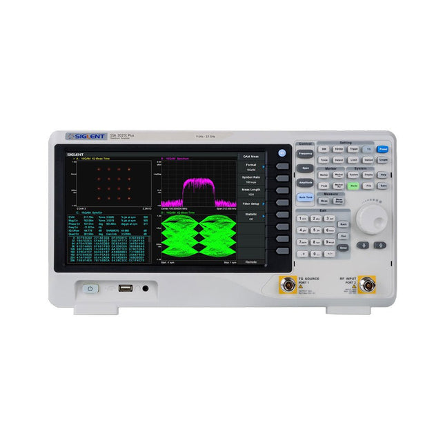
The Siglent SSA3021X Plus spectrum analyzer is a powerful and flexible tool for RF signal and network analysis. With a frequency range of 2.1 GHz, the analyzer delivers reliable automatic measurements and multiple modes of operation: spectrum analyzer the base, optional functions include RF power measurement, vector signal modulation analysis, reflection measurement, and EMI test.
Applications include broadcast monitoring/evaluation, site surveying, S-parameter measurement, analog/digital modulation analysis, EMI pre-compliance test, research and development, education, production, and maintenance.
Features
Spectrum Analyzer Frequency Range from 9 kHz to 2.1 GHz
–161 dBm/Hz Displayed Average Noise Level (Typ.)
–98 dBc/Hz. @ 10 kHz Offset Phase Noise (1 GHz, Typ.)
Level Measurement Uncertainty <0.7 dB (Typ.)
1 Hz Minimum Resolution Bandwidth (RBW)
Preamplifier (Std.)
Tracking Generator (incl. free of charge)
Analog and Digital Signal Modulation Analysis Mode (opt.)
Reflection Measurement Kit (opt.)
EMI Filter and Quasi-Peak Detector Kit (opt.)
Advanced Measurement Kit (opt.)
10.1-inch Multi-Touch Screen , Mouse and Keyboard supported
Web Browser Remote Control on PC and Mobile Terminals and File Operation
Specifications
SSA3015X Plus
SSA3021X Plus
SSA3032X Plus
SSA3075X Plus
Frequency Range
9 kHz ~ 1.5 GHz
9 kHz ~ 2.1 GHz
9 kHz ~ 3.2 GHz
9 kHz ~ 7.5 GHz
Resolution Bandwidth
1 Hz ~ 1 MHz
1 Hz ~ 1 MHz
1 Hz ~ 1 MHz
1 Hz ~ 3 MHz
Phase Noise
<–99 dBc/Hz
<–98 dBc/Hz
<–98 dBc/Hz
<–98 dBc/Hz
Total Amplitude Accuracy
<1.2 dB
<0.7 dB
<0.7 dB
<0.7 dB
Display Average Noise Level
–156 dBm/Hz
–161 dBm/Hz
–161 dBm/Hz
–165 dBm/Hz
Included
Siglent SSA3021X Plus spectrum analyzer
USB cable
Power cord
Quick start guide
Downloads
Datasheet
Manual
Documentation
Firmware