
Search results for "platino OR v1 OR 4 OR 150555 OR 1"
-
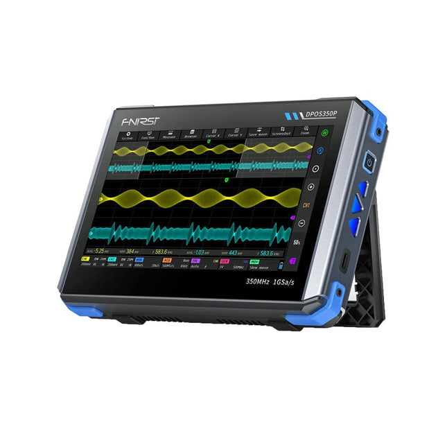
FNIRSI FNIRSI DPOS350P (4-in-1) 2-ch Tablet Oscilloscope (350 MHz) + Signal Generator + Frequency Response Analyzer + Spectrum Analyzer
2 Channels • 350 MHz • 1 GSa/s • 50,000 wfm/s • 7 inch Touchscreen The FNIRSI DPOS350P is a sleek 4-in-1 powerhouse in tablet form! This compact and portable device packs serious functionality: it combines a 2-channel oscilloscope (350 MHz), a signal generator (50 MHz), a frequency response analyzer (50 MHz), and a spectrum analyzer (200 kHz–350 MHz) – all in one unit. Whether you're in R&D, troubleshooting, or field testing, the DPOS350P delivers the tools you need to measure, generate, analyze, and visualize electronic signals with precision and clarity. Its responsive high-resolution touchscreen and intuitive controls make signal analysis fast, flexible and efficient. Features Powerful Multi-Function Integration 350 MHz 2-channel oscilloscope with 1 GSa/s real-time sampling 50 MHz signal generator with 14 standard + custom waveforms Spectrum analyzer (200 kHz–350 MHz): Perfect for EMI, RF & HF testing Frequency response analyzer (FRA) up to 50 MHz High-Performance Waveform Capture 50,000 wfm/s refresh rate for real-time signal clarity 350 MHz bandwidth (single-channel mode) Detects rare and low-probability anomalies Crisp Display & Smooth Operation 7" IPS touchscreen (1024 x 600 resolution) Switch between grayscale and color temperature display Easy to operate in various test environments Reliable, Protected & Fast-Charging High-voltage protection up to 400 V Fast charging with QC 18 W (full charge in 2 hours) Built for stable long-term operation Data Storage & Export Save up to 500 waveform records + 90 screenshots USB export for easy reporting and offline analysis Specifications General Display 7 inch (IPS full viewing angle) Resolution 1024 x 600 pixels Interaction mode Capacitive touch screen Total power consumption 10 W Power-on configuration 5 presets Charging QC 18 W, 12 V/1.5 A (USB-C) Battery 3.7 V, 8000 mAh lithium battery Battery life approx. 3 hours in operation, 5 hours standby Heat dissipation Air cooling Expansion interface USB data port Automatic shutdown 15~60 minutes / off Firmware upgrade Support .iso image upgrade Languages English / Portuguese / Russian / Chinese Dimensions 190 x 128 x 37 mm Oscilloscope Analog channels 2 Analog bandwidth 350 MHz Rise time 1ns Real-time sampling rate 1 GSa/s Memory depth 60 Kpts Input impedance 1 MΩ / 14PF Time base range 5ns ~ 50s Roll time base 50ms ~ 50s Vertical sensitivity 2 mV ~ 20 V (1X) Vertical range 16 mV ~ 160 V (1X) DC accuracy ±2% Time accuracy ±0.01% Input coupling DC / AC Probe attenuation 1X / 10X / 100X Hardware bandwidth limit 150M / 20M High resolution mode 8bit ~ 16bit Parameter measurements 12 types Cursor measurement Time, period, frequency, level, voltage Trigger detection Digital trigger Trigger channel CH1 / CH2 Trigger mode Auto / Single / Normal Trigger edge Rising edge / Falling edge Trigger suppression L1 ~ L3 Trigger level Manual / automatic 10% ~ 90% Screenshot storage 90 pictures Waveform storage 500 groups Background grid Display / hide Waveform movement Coarse adjustment / fine adjustment Overvoltage protection Withstand voltage 400 V Waveform brightness Adjustable Simple FFT display Yes Digital fluorescence Yes Color temperature display Yes X-Y mode Yes ZOOM time base Yes One-key automatic adjustment Yes One-key return to zero Yes Data browser Yes Signal Generator Waveform types 14 standard functions + captured waveform Frequency 0~50 MHz (sine wave only, other waveforms up to 10M/5M/3M) Amplitude 0~5 VPP Offset -2.5 V ~ +2.5V Duty cycle 0.1~99.9% Frequency resolution 1 Hz Amplitude resolution 1 mV Offset resolution 1 mV Duty cycle resolution 0.1% Customizable captured waveform 500 groups Frequency Response Analyzer (FRA) Excitation signal frequency 100 Hz ~ 50 MHz Excitation signal amplitude 0~5 VPP Excitation signal offset -2.5V ~ +2.5V Excitation frequency count 20~500 Cursor measurement Frequency / gain / phase Operating mode Single / cyclic System calibration Yes Spectrum Analyzer Conversion method FFT FFT length 4K ~ 32K Frequency range 200 KHz ~ 350 MHz Level range -60 dBmV ~ +260 dBmV Cursor measurement Frequency / amplitude Marking parameter Maximum energy harmonic Waterfall chart Yes 3D waterfall chart Yes Automatic adjustment Yes System calibration Yes Included 1x FNIRSI DPOS350P Oscilloscope (4-in-1) 2x 350 MHz Probes 1x QC 18 W Fast Charger (EU) 1x USB-C Cable 1x Alligator Clip 1x Storage Bag 1x Manual Downloads Manual Firmware
€ 309,00€ 259,00Best Price
-
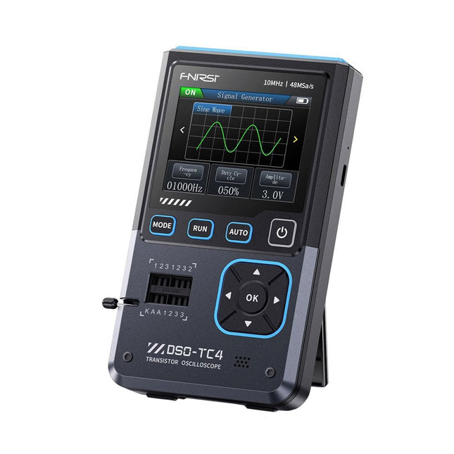
FNIRSI FNIRSI DSO-TC4 (3-in-1) Oscilloscope (10 MHz) + Transistor Tester + Signal Generator
The FNIRDSI DSO-TC4 is a multifunctional transistor oscilloscope that is both comprehensive and practical. It is designed for use in maintenance and R&D applications, integrating an oscilloscope, transistor tester, and signal generator into a single device. Features Equipped with a 2.8-inch TFT color screen for a clear and intuitive display Built-in high-capacity rechargeable lithium battery (1500 mAh) with a standby time of up to 4 hours Compact and lightweight, ideal for mobile use Specifications Oscilloscope Analog Bandwidth 10 MHz Real-Time Sampling Rate 48 MSa/s Input Impedance 1 MΩ Coupling Mode AC/DC Test Voltage Range 1:1 Probe: 80 Vpp (+40 V) 10:1 Probe: 800 Vpp (+400 V) Vertical Sensitivity 10 mV/div~10 V/div (X1 range) Vertical Displacement Adjustable with indication Time Base Range 50ns~20s Trigger Mode Auto/Normal/Single Trigger Type Rising edge, Falling edge Trigger Level Adjustable with indication Waveform Freeze Yes (HOLD function) Automatic Measurement Max, Min, Avg, RMS, Vpp, Frequency, Cycle, Duty Cycle Component Tester Transistor Amplification factor "hfe"; Base-Emitter voltage "Ube", Ic/Ie, Collector-Emitter reverse leakage current "Iceo", Ices, Forward voltage drop of protection diode "Uf" Diode Forward voltage drop <5 V (Forward voltage drop, Junction capacitance, Reverse leakage current) Zener Diode 0.01~32 V Reverse Breakdown Voltage (K-A-A Test Area) Field-Effect Transistor (FET) JFET: Gate capacitance "Cg", Drain current Id under "Vgs", Forward voltage drop of protection diode "Uf" IGBT: Drain current Id under Vgs, Forward voltage drop of protection diode Uf MIOSTET: Threshold voltage "Vt", Gate capacitance "Cg", Drain-Source resistance "Rds", Forward voltage drop of protection diode "Uf" Unidirectional SCR Trigger voltage <5V, Gate level (Gate voltage) Bidirectional SCR Trigger current <6mA (Gate voltage) Capacitor 25pF~100mF, Capacitance value, Loss factor "Vloss" Resistor 0.01Ω~50MΩ Inductor 10μH~1000μH, DC resistance DS18B20 Temperature sensor, Pins: GND, DQ, VDD DHT11 Temperature and humidity sensor, Pins: VDD, DATA, GND Signal Generator Output Waveform Supports 13 waveform outputs Waveform Frequency 0-50 KHz Square Wave Duty Cycle 0-100% Waveform Amplitude 0.1-3.0 V General Display 2.8-inch TFT color screen Backlight Brightness adjustable Power Supply USB-C (5 V/1 A) Battery 3.7 V/1500 mAh Languages English, German, Spanish, Portuguese, Russian, Chinese, Japanese, Korean Dimensions 90 x 142 x 27.5 mm Weight 186 g Included 1x FNIRSI DSO-TC4 (3-in-1) Oscilloscope (10 MHz) 1x P6100 Oscilloscope probes (10X) 1x Alligator clip probe 3x Test hooks 1x Adapter 1x USB-C charging cable 1x Manual Downloads Manual Firmware V0.0.7 (+V1.0.9)
€ 89,95€ 74,95Best Price
-
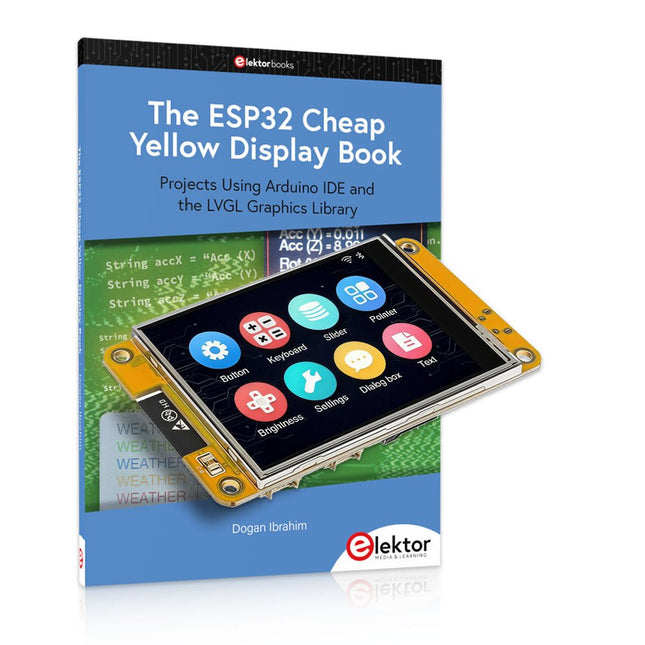
Elektor Bundles The ESP32 Cheap Yellow Display Bundle
Over 40 Fully Tested ESP32 Projects Using Arduino IDE and the LVGL Graphics Library This bundle includes the ESP32 Cheap Yellow Display (CYD) – a compact development board combining a standard ESP32 microcontroller with a 320x240 pixel TFT color display. The board also features multiple connectors for GPIO, serial communication (TX/RX), power, and ground. The built-in display is a major advantage, allowing users to create complex, graphics-based projects without the need for external LCDs or displays. The accompanying book introduces the CYD board's hardware and on-board connectors in detail. It provides a range of beginner to intermediate-level projects developed using the popular Arduino IDE 2.0. Both basic graphics functions and the powerful LVGL graphics library are covered, with practical projects illustrating each approach. All included projects have been fully tested and are ready to use. The book provides block diagrams, circuit schematics, complete code listings, and step-by-step explanations. With the LVGL library, readers can create modern, full-color graphical interfaces using widgets such as buttons, labels, sliders, calendars, keyboards, charts, tables, menus, animations, and more. ESP32 Cheap Yellow Display Board This development board (also known as "Cheap Yellow Display") is powered by the ESP-WROOM-32, a dual-core MCU with integrated Wi-Fi and Bluetooth capabilities. It operates at a main frequency of up to 240 MHz, with 520 KB SRAM, 448 KBROM, and a 4 MB Flash memory. The board features a 2.8-inch display with a resolution of 240x320 and resistive touch. Furthermore, the board includes a backlight control circuit, touch control circuit, speaker drive circuit, photosensitive circuit, and RGB-LED control circuit. It also provides a TF card slot, serial interface, DHT11 temperature and humidity sensor interface, and additional IO ports. The module supports development in Arduino IDE, ESP-IDE, MicroPython, and Mixly. Applications Image transmission for Smart Home device Wireless monitoring Smart agriculture QR wireless recognition Wireless positioning system signal And other IoT applications Specifications Microcontroller ESP-WROOM-32 (Dual-core MCU with integrated Wi-Fi and Bluetooth) Frequency Up to 240 MHz (computing power is up to 600 DMIPS) SRAM 520 KB ROM 448 KB Flash 4 MB Operating voltage 5 V Power consumption approx. 115 mA Display 2.8-inch color TFT screen (240 x 320) Touch Resistive Touch Driver chip ILI9341 Dimensions 50 x 86 mm Weight 50 g Downloads GitHub This bundle contains: The ESP32 Cheap Yellow Display Book (normal price: €35) ESP32 Cheap Yellow Display Board (normal price: €25) 1x ESP32 Dev Board with 2.8" Display and acrylic Shell 1x Touch pen 1x Connector cable 1x USB cable
€ 59,95€ 49,95Best Price
-

Red Pitaya Red Pitaya STEMlab 125-14 PRO Gen 2 Starter Kit (incl. Book)
This bundle includes the Red Pitaya STEMlab 125-14 PRO Gen 2 Starter Kit and the new book "Experimenting with Red Pitaya STEMlab Gen 2". The Red Pitaya STEMlab 125-14 PRO Gen 2 Starter Kit is a powerful and flexible platform for signal processing, data acquisition, and electronic measurement applications. Designed for engineers, developers, researchers, and educators, this kit provides everything required to start building advanced measurement and control systems. At the core of the kit is the STEMlab 125-14 PRO Gen 2 board, an upgraded and ultra-lightweight development platform. Powered by the Xilinx Zynq-7010 SoC with 512 MB of RAM, it combines FPGA programmability with ARM processing power to enable high-performance instrumentation and custom signal-processing solutions. The board offers 14-bit ADC and DAC resolution, a 125 MS/s sampling rate, an input range of ±20 V, and up to 60 MHz bandwidth. Its improved low-noise analog front-end, USB-C connectivity, and compact design make it suitable for demanding applications such as RF development, radar systems, photonics research, software-defined radio (SDR), and industrial automation. The Starter Kit includes all essential accessories for immediate use: a microSD card with preinstalled operating system, power supply, Ethernet cable for remote access, two 100 MHz oscilloscope probes, and SMA-to-BNC adapters for flexible signal connections. The Red Pitaya STEMlab 125-14 PRO Gen 2 Starter Kit is an excellent platform for rapid prototyping, FPGA development, measurement instrumentation, and advanced electronics experimentation. Features 14-bit ADC and DAC resolution 125 MS/s sampling rate ±20 V input range Up to 60 MHz bandwidth Xilinx Zynq-7010 SoC (FPGA + ARM processor) 512 MB RAM Low-noise analog front- and back-ends Applications RF development and testing Radar and wireless systems Software-defined radio (SDR) Photonics and optical research Industrial automation and control systems Signal analysis and instrumentation Rapid prototyping of electronic measurement systems Specifications Processor Dual-core ARM Cortex-A9 FPGA AMD Xilinx Zynq-7010 SoC RAM 512 MB (4 Gb) Storage microSD card (up to 32 GB) Operating System Linux-based Red Pitaya OS ADC Resolution 14-bit DAC Resolution 14-bit Bandwidth 60 MHz (DC) Sampling Rate 125 MS/s Analog Input Channels 2 Analog Output Channels 2 Input Voltage Range ±1 V (LV) / ±20 V (HV) Input Impedance 1 MΩ / 10 pF Output Voltage Range ±1 V Ethernet 1x Gigabit Ethernet (RJ45) USB 2x USB-C 2.0 (for power and console) Digital I/O 16x GPIO (3.3 V) Communication Interfaces I²C, SPI, UART, CAN Power Supply 5 V/3 A via USB-C Dimensions 106.8 x 60.0 x 17.9 mm Included 1x Red Pitaya STEMlab 125-14 PRO Gen 2 board 2x 100 MHz oscilloscope probes 2x SMA-to-BNC adapters 1x microSD card with preinstalled OS 1x USB-C Power supply 1x Ethernet cable Downloads Documentation Schematics Book: Experimenting with Red Pitaya STEMlab Gen 2 With this new book, Red Pitaya goes beyond a versatile board. It becomes a powerful laboratory instrument for precision measurement, analysis, and control. From the fundamentals of electronic project development, monitoring, control, and design to testing, this book walks you step-by-step through everything you need to know to harness the full potential of Red Pitaya hardware and software. The book presents real-time, FPGA-based projects that are developed on a PC using the Vivado environment, then transferred to the Red Pitaya for execution and testing. You will learn about enhanced performance, expanded I/O capabilities, improved FPGA features, and advanced connectivity options that open up new frontiers for precision measurement, monitoring, and control in your embedded applications. Inside the book you will discover: A deep dive into Red Pitaya architecture and hardware design Electronic experiments using Red Pitaya for measurement and monitoring Hands-on projects using the Python programming language Practical guidance for FPGA programming using Red Pitaya Red Pitaya FPGA projects using the Verilog HDL under Vivado IDE Practical design of electronic projects including measurement and testing Step-by-step examples that bridge theory and real-world implementation Whether you are designing your own electronic circuits, developing signal analysis tools, or creating real-time control or monitoring systems, this book provides you the knowledge and confidence you need to fully learn and customize the Red Pitaya platform.
€ 799,00
Best Price
-

JOY-iT Joy-Pi Advanced Development Platform (incl. Raspberry Pi 4, 8 GB)
The Joy-Pi Advanced is a compact and powerful device that allows you to realize your projects quickly and easily. Whether you already have a lot of experience, or next to none, the Joy-Pi Advanced lets you unleash your creativity. Thanks to its compatibility with a wide range of platforms, including Raspberry Pi, Raspberry Pi Pico, Arduino Nano, BBC micro:bit, and NodeMCU ESP32, you can easily and quickly access your preferred platform. In addition, the Joy-Pi Advanced features more than 30 stations, lessons, and modules, giving you an unlimited variety of ways to get your projects done. With the self-developed learning center, you can not only improve your skills but also create new projects. The learning center offers a wealth of information and tutorials that will guide you step by step through your projects. Joy-Pi Advanced is characterized in particular by its intelligent switch units, which allow an extended use of the available pins. A total of three switch units are integrated, each equipped with 12 individual switches that provide precise control of the connected sensors and modules. This system solves the well-known problem of limited pin count that occurs with conventional microcontrollers. The switch units allow you to operate a large number of sensors and modules in parallel by switching them on and off individually. This simulates multiple pin assignment, allowing you to exploit the full power of your projects without compromising functionality. By combining innovative adapter boards and the micro:bit slot, you can achieve seamless compatibility with a wide range of microcontrollers such as Raspberry Pi Pico, NodeMCU ESP32, micro:mit and Arduino Nano. The specially developed adapter boards are designed to perfectly match the respective microcontroller. By plugging the microcontroller onto the appropriate adapter board and then plugging it into the micro:bit slot, the Joy-Pi Advanced quickly and easily becomes compatible with the different microcontrollers. This allows seamless integration of your preferred platform and the ability to combine the strengths of the different microcontrollers in your projects. This way, you can fully focus on your creative projects without worrying about the compatibility of different microcontrollers. The Joy-Pi Advanced simplifies the development process and gives you the possibility to design your projects flexibly and individually. Features Highly integrated development platform & learning center Fast, easy & wireless combination of various sensors & actuators Installation option for Raspberry Pi 4 Compatible with various microcontrollers Self-developed, didactic learning platform for Raspberry Pi & Windows Specifications Compatible to Raspberry Pi 4, Arduino Nano, NodeMCU ESP32, BBC micro:bit, Raspberry Pi Pico Installed sensors, actuators & components 39 Learning platform Over 40 entries in the know-ledge database, 10 projects, 10 learning tasks, 14 visions Displays 7-segment display, 16x2 display, 1.8“ TFT display, 0.96" OLED display, 8x8 RGB matrix Sensors DS18B20, shock sensor, hall sensor, barometer, sound sensor, gyroscope, PIR sensor, Light barrier, NTC, Light sensor, 6x touch sensor, color sensor, ultrasonic distance sensor, DHT11 temperature & humidity sensor Control Joystick, 5x switches, potentiometer, rotary encoder, 4x4 button matrix, relays, PWM fan Motors Servo interface, Stepper motor interface, Vibration motor Measuring & conversion modules Analog-Digital Converter, Level converter, voltmeter, Variable voltage supply Other components RTC real time clock, buzzer, EEPROM memory, infrared receiver, breadboard, RFID reader Adapter boards Adapter for NodeMCU ESP32, Arduino Nano & Raspberry Pi Pico, Board connectors for Raspberry Pi & External Boards Electronic components Infrared remote control, RFID chip, RFID card, 6x alligator clips, microSD card reader, servo motor, stepper motor, 32 GB microSD card Components 40x resistors, 3x green LEDs, 3x yellow LEDs, 3x red LEDs, 1x transistor, 5x buttons, 1x potentiometer, 2x capacitors Other accessories Screw assortment, screwdriver, accessory storage bag, power supply & power cable, servo mount Power supply Built-in power supply: 36 W, 12 V, 3 A Case connector: Small device plug C8 Voltage outputs 12 V, 5 V, 3.3 V, Variable voltage output (2-11 V) Data buses & signal outputs I²C, SPI, Analog to digital converter Battery (RTC) CR2032 Dimensions 327 x 200 x 52 mm Included Raspberry Pi 4 (8 GB RAM) Downloads Joy-Pi website Datasheet Manual
€ 529,00€ 469,00Best Price
-

FNIRSI FNIRSI TDM-120P Thermal Imaging Multimeter
The FNIRSI TDM-120P is a thermal imaging multimeter that combines thermal imaging technology with traditional multimeter functions, delivering more comprehensive and intuitive test results for electrical testing and related applications. It is widely used in fields such as electrical engineering, industrial manufacturing, construction, and security monitoring. The TDM-120P provides reliable technical support for equipment testing, fault diagnosis, and maintenance management, helping to improve production efficiency, product quality, and overall safety. Features 2-in-1: Thermal Imager + True RMS Multimeter (19,999 Counts) 120 x 90 HD Imaging | <60 mK High Thermal Sensitivity -20°C to 400°C (-4°F to 752°F) Temperature Range | 0.01–1.00 Adjustable Emissivity 2.8" LCD Touch Screen | 7 Color Palettes | One-Click Save & USB Export Full Multimeter Functions: AC/DC Voltage, Resistance, and Capacitance Wide Application: HVAC, Leak Detection, Electrical & Automotive Repair Specifications 7 Color Palettes Arctic / Hot Iron / Iron Red / Rainbow / Lava / Black Hot / White Hot Detector Type Vanadium oxide Field of View 50° Screen 2.8-inch LCD touchscreen Frame Rate ≤25 Hz Infrared Resolution 120 x 90 Temperature Measurement Display Center point, automatic high/low temperature tracking Temperature Range -20°C ~ 400°C (-4°F ~ 752°F) Temperature Unit °C / °F Accuracy ±2°C or ±2% (maximum value measured) High/Low Temperature Alarm Yes Emissivity 0.01-1 adjustable Languages English, Chinese Multimeter DC Voltage Range: 1.9999V / 19.999V / 199.99V / 1000V Accuracy: ±(0.5% +3) AC Voltage Range: 1.9999V / 19.999V / 199.99V / 750.0V Accuracy: ±(1% +3) Resistance Range: 19.999MΩ / 1.9999MΩ / 199.99KΩ / 19.999KΩ Accuracy: ±(0.5% +3) Range: 1.9999KΩ / 199.99Ω Accuracy: ±(2.0% +3) Capacitance Range: 999.9μF / 99.99μF / 9.999μF / 999.9nF / 99.99nF / 9.999nF Accuracy: ±(2.0% +5) Range: 9.999mF / 99.99mF Accuracy: ±(5.0% +20) Diode Yes Continuity Yes Included 1x FNIRSI TDM-120P Thermal Imaging Multimeter 2x Multimeter Test Leads 1x Storage bag 1x USB cable 1x Manual Downloads Manual Firmware v1.2.6
€ 199,95€ 179,95Best Price
-
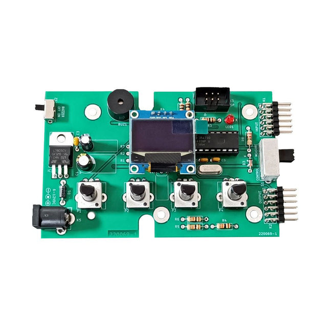
Elektor Labs Elektor Super Servo Tester Kit
The Elektor Super Servo Tester can control servos and measure servo signals. It can test up to four servo channels at the same time. The Super Servo Tester comes as a kit. All the parts required to assemble the Super Servo Tester are included in the kit. Assembling the kit requires basic soldering skills. The microcontroller is already programmed. The Super Servo Tester features two operating modes: Control/Manual and Measure/Inputs. In Control/Manual mode the Super Servo Tester generates control signals on its outputs for up to four servos or for the flight controller or ESC. The signals are controlled by the four potentiometers. In Measure/Inputs the Super Servo Tester measures the servo signals connected to its inputs. These signals may come from for instance an ESC, a flight controller, or the receiver or another device. The signals are also routed to the outputs to control the servos or the flight controller or ESC. The results are shown on the display. Specifications Operating modes Control/Manual & Measure/Inputs Channels 3 Servo signal inputs 4 Servo signal outputs 4 Alarm Buzzer & LED Display 0.96' OLED (128 x 32 pixels) Input voltage on K5 7-12 VDC Input voltage on K1 5-7.5 VDC Input current 30 mA (9 VDC on K5, nothing connected to K1 and K2) Dimensions 113 x 66 x 25 mm Weight 60 g Included Resistors (0.25 W) R1, R3 1 kΩ, 5% R2, R4, R5, R6, R7, R9, R10 10 kΩ, 5% R8 22 Ω, 5% P1, P2, P3, P4 10 kΩ, lin/B, vertical potentiometer Capacitors C1 100 µF 16 V C2 10 µF 25 V C3, C4, C7 100 nF C5, C6 22 pF Semiconductors D1 1N5817 D2 LM385Z-2.5 D3 BZX79-C5V1 IC1 7805 IC2 ATmega328P-PU, programmed LED1 LED, 3 mm, red T1 2N7000 Miscellaneous BUZ1 Piezo buzzer with oscillator K1, K2 2-row, 12-way pinheader, 90° K5 Barrel jack K4 1-row, 4-way pin socket K3 2-row, 6-way boxed pinheader S1 Slide switch DPDT S2 Slide switch SPDT X1 Crystal, 16 MHz 28-way DIP socket for IC2 Elektor PCB OLED display, 0.96', 128 x 32 pixels, 4-pin I²C interface Links Elektor Magazine Elektor Labs
€ 59,95€ 49,95Best Price
-
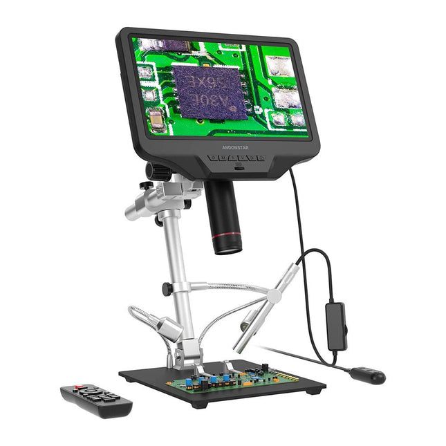
Andonstar Andonstar AD409 Pro-ES 10.1" HDMI Digital Microscope (incl. Endoscope)
The Andonstar AD409 Pro-ES is a digital microscope with an extra-high stand that is also equipped with an endoscope. The microscope allows clear observation of the sides of components, the inside of pipes, etc., enabling 360° observation without dead angles. The microscope also has a remote control that allows you to easily switch between the following image modes: two-lens, microscope and endoscope. Features High-quality metal lens and focusing barrel Professional HDMI digital microscope supports multiple output methods Soldering Microscope with Pro Metal Stand Unique UV filter design 8 Levels adjustable LED Lights Convenient Wireless Remote Control Professional Measurement Software Specifications Screen size 10.1 inch (25.7 cm) Image sensor 4 MP Video output UHD 2880x2160 (24fps)FHD 1920x1080 (60fps/30fps)HD 1280x720 (120fps) Video format MP4 Magnification Up to 300 times (27 inch HDMI monitor) Photo resolution Max. 12 MP (4032x3024) Photo format JPG Focus range Min. 5 cm Frame Rate Max. 120fps Video interface HDMI Storage microSD card (up to 64 GB) PC support Windows, PC software with measurement Mobile phone, tablet terminal support Support WiFi connection and measurement Power source 5 V DC Light source 2 LEDs with the stand Endoscope Yes Stand size 18 x 20 x 32 cm Included 1x Andonstar AD409 Pro-ES Digital Microscope 1x Endoscope 1x Metal stand with 2 LEDs 1x UV filter (already assembled in the lens) 1x IR remote 1x Switch cable 1x Power adapter 1x Wrench 2x Metal clips 1x HDMI cable 1x User manual Downloads Manual Software
€ 339,00€ 289,00Best Price
-

FNIRSI FNIRSI DLA-16/32 Plus Logic Analyzer (16/32 Channels)
The FNIRSI DLA Series combines high-performance USB 3.0 logic analysis with flexible multi-channel signal capture for debugging and analyzing digital circuits and embedded systems. The series is available in two versions: the DLA-16 Plus with 16 digital channels and the DLA-32 Plus with 32 digital channels. Both models offer sampling rates of up to 1 GSa/s, 4 Gbit of onboard memory, and support for 120+ protocol decoders. With Buffer, Stream, and Roll acquisition modes, they are suitable for both high-speed signal analysis and long-term monitoring. Choose the DLA-16 Plus for higher sampling rates when using all channels, or the DLA-32 Plus when you need more channels and advanced serial and parallel triggering. Features Available with 16 or 32 digital input channels Up to 1 GSa/s sampling rate DLA-16 Plus: up to 500 MSa/s with all 16 channels DLA-32 Plus: up to 250 MSa/s with all 32 channels 4 Gbit onboard memory High-speed USB 3.0 interface Acquisition modes: Buffer, Stream, and Roll Support for 120+ protocol decoders Advanced triggering options 4 PWM outputs with 1 Hz–20 MHz frequency range CSV and BIN data export Specifications DLA-16 Plus DLA-32 Plus Digital Channels 16 32 Max. Sampling Rate 1 GSa/s Sampling Rate (1 Channel) 1 GSa/s Sampling Rate (8 Channels) 1 GSa/s Max. Buffer Sampling 16 CH @ 500 MSa/s 32 CH @ 250 MSa/s Max. Stream Sampling 16 CH @ 125 MSa/s 32 CH @ 50 MSa/s Hardware Memory 4 Gbit Interface USB 3.0 / USB-C Max. USB Transfer Rate 5 Gbit/s Acquisition Modes Buffer / Stream / Roll Protocol Decoders 120+ Custom Protocol Support Yes Trigger Modes Rising Edge, Falling Edge, High, Low, Any Edge Advanced Trigger Standard Triggering Serial and Parallel Parallel Trigger Stages – Up to 16 PWM Outputs 4 PWM Output Voltage 3.3 V PWM Frequency 1 Hz–20 MHz Data Export CSV, BIN Dimensions 90 x 81 x 11.5 mm Included 1x FNIRSI DLA-16/32 Plus Logic Analyzer 4 Sets x 5 Shielded Cables 18x Mini IC Test Hooks (High Configuration Version) 1x USB 3.0 Data Cable 10x IC Test Hooks 1x Transparent Storage Case for Test Hooks 1x Storage Bag 1x Manual Downloads Manual
-

Elektor Bundles Universal Maker Sensor Bundle
Over 180 Projects with Raspberry Pi, Pico W, Arduino, and ESP32 This bundle contains the Universal Maker Sensor Kit, which consists of many sensors, actuators, displays, and motors. It’s perfect for environmental monitoring, smart home projects, robotics, and game controllers. The new Elektor book describes the design of many projects using the kit together with the popular Raspberry Pi, Raspberry Pi Pico W, Arduino Uno, and the ESP32 family of development boards. You can choose any of these development boards for your projects and either use the provided programs as they are, or modify these programs to suit your applications. This bundle contains: Book: Universal Maker Sensor Kit (normal price: €45) Universal Maker Sensor Kit for Raspberry Pi, Pico W, Arduino, ESP32 (normal price: €70) Book: Universal Maker Sensor Kit Learn to use more than 35 Sensors and Actuators with C++, Python, and MicroPython This book contains over 180 projects for all four major development boards (Arduino, Raspberry Pi, Pico W, and ESP32). Depending on the development board, projects are available in the C, Python, or MicroPython programming languages. The project titles, brief descriptions, wiring diagrams, and full program listings together with their detailed descriptions are given in the guide. Universal Maker Sensor Kit (for Raspberry Pi, Pico W, Arduino, ESP32) Discover endless creativity with the Universal Maker Sensor Kit, designed for use with Raspberry Pi, Pico W, Arduino, and ESP32. This versatile kit offers compatibility across popular development platforms, including Arduino Uno R4 Minima/WiFi, Uno R3, Mega 2560, Raspberry Pi 5, 4, 3B+, 3B, Zero, Pico W, and ESP32. Featuring over 35 sensors, actuators, and displays, it's perfect for projects ranging from environmental monitoring and smart home automation to robotics and interactive gaming. Step-by-step tutorials in C/C++, Python, and MicroPython guide beginners and experienced makers alike through 169 exciting projects. Features Wide Compatibility: Fully supports Arduino (Uno R3, Uno R4 Minima/WiFi, Mega 2560), Raspberry Pi (5, 4, 3B+, 3B, Zero, Pico W), and ESP32, enabling extensive flexibility across numerous development platforms. Includes instructions for building 169 projects. Comprehensive Components: Features more than 35 sensors, actuators, and display modules suitable for diverse projects such as environmental monitoring, smart home automation, robotics, and interactive game controllers. Detailed Tutorials: Provides clear, step-by-step tutorials covering Arduino, Raspberry Pi, Pico W, ESP32, and each included component. Tutorials are available in C/C++, Python, and MicroPython, catering effectively to both beginners and experienced makers. Suitable for All Skill Levels: Offers structured projects designed to guide users seamlessly from beginner to advanced proficiency in electronics and programming, enhancing creativity and technical expertise. Kit includes Breadboard Button Module Capacitive Soil Moisture Module Flame Sensor Module Gas/Smoke Sensor Module (MQ2) Gyroscope & Accelerometer Module (MPU6050) Hall Sensor Module Infrared Speed Sensor Module IR Obstacle Avoidance Sensor Module Joystick Module PCF8591 ADC DAC Converter Module Photoresistor Module PIR Motion Module (HC-SR501) Potentiometer Module Pulse Oximeter and Heart Rate Sensor Module (MAX30102) Raindrop Detection Module Real Time Clock Module (DS1302) Rotary Encoder Module Temperature Sensor Module (DS18B20) Temperature and Humidity Sensor Module (DHT11) Temperature, Humidity & Pressure Sensor (BMP280) Time of Flight Micro-LIDAR Distance Sensor (VL53L0X) Touch Sensor Module Ultrasonic Sensor Module (HC-SR04) Vibration Sensor Module (SW-420) Water Level Sensor Module I²C LCD 1602 OLED Display Module (SSD1306) RGB LED Module Traffic Light Module 5 V Relay Module Centrifugal Pump L9110 Motor Driver Module Passive Buzzer Module Servo Motor (SG90) TT Motor ESP8266 Module JDY-31 Bluetooth Module Power Supply Module Documentation Online Tutorial
€ 114,95€ 94,95Best Price
-
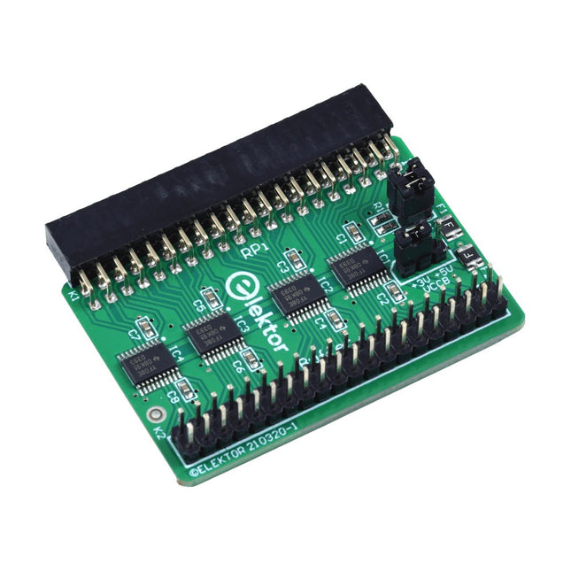
Elektor Labs Elektor Raspberry Pi Buffer Board
When you experiment with the Raspberry Pi on a regular basis and you connect a variety of external hardware to the GPIO port via the header you may well have caused some damage in the past. The Elektor Raspberry Pi Buffer Board is there to prevent this! The board is compatible with Raspberry Pi Zero, Zero 2 (W), 3, 4, 5, 400 and 500. All 26 GPIOs are buffered with bi-directional voltage translators to protect the Raspberry Pi when experimenting with new circuits. The PCB is intended to be inserted in the back of Raspberry Pi 400/500. The connector to connect to the Raspberry Pi is a right angled 40-way receptacle (2x20). The PCB is only a fraction wider. A 40-way flat cable with appropriate 2x20 headers can be connected to the buffer output header to experiment for instance with a circuit on a breadboard or PCB. The circuit uses 4x TXS0108E ICs by Texas Instruments. The PCB can also be put upright on a Raspberry Pi. Downloads Schematics Layout
€ 34,95
Members: € 31,46
-
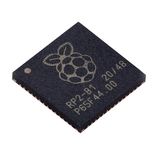
Raspberry Pi Foundation Raspberry Pi RP2040 Microcontroller (10 pcs)
Specifications Dual ARM Cortex-M0+ @ 133 MHz 264 kB on-chip SRAM in six independent banks Support for up to 16 MB of off-chip Flash memory via dedicated QSPI bus DMA controller Fully-connected AHB crossbar Interpolator and integer divider peripherals On-chip programmable LDO to generate core voltage 2x on-chip PLLs to generate USB and core clocks 30x GPIO pins, 4 of which can be used as analogue inputs Peripherals 2x UARTs 2x SPI controllers 2x I²C controllers 16x PWM channels USB 1.1 controller and PHY, with host and device support 8x PIO state machines What you'll get 10x bare RP2040 chips
€ 7,95€ 3,18Best Price


