
Search results for "elektor OR circuit OR special OR 2023 OR fr"
-

Elektor Digital Elektor Novembre/Décembre 2020 (PDF)
Elektor Novembre/Décembre 2020 (PDF)
€ 10,95
-

Elektor Academy Pro Arduino for STM32 (Programming Course)
This complete STM32 microcontroller programming course features a textbook, a component kit, hands-on projects, and a comprehensive online course. It is ideal for step-by-step learning of embedded systems programming with Arduino using a practical, hands-on approach. A Practical Introduction to Embedded Systems with the STM32 This course is designed for people who are new to embedded systems and looking for a structured, example-driven way to get started. A kit of parts comprising LEDs and resistors, switches, sensors and actuators, displays, a breadboard and wires, and more is included. These are used in the course to illustrate example applications. No prior experience with Arduino or embedded development is required. Each section features hands-on examples and mini projects designed to reinforce key concepts and inspire deeper exploration. By the end of the course, you’ll be able not only to reproduce the examples but also to build on them with your own ideas and applications. What Will You Learn? Microcontroller programming in C/C++ with the STM32 using the Arduino IDE Working with Digital I/O, read buttons and encoders, control LEDs and relays Read analog inputs, voltages, and analog sensors Generating analog output signals and PWM Use serial communication like UART, I²C and SPI to control displays and read digital sensors and SD cards Managing time Working with interrupts Real-time sensor input and control via buttons, LEDs, and displays Control actuators like relays and servo motors Debug programs using breakpoints and stepping through code Who Is It For? Students and self-learners exploring embedded systems Makers and IoT enthusiasts looking to improve their hardware skills Educators and trainers seeking ready-to-teach material What's Inside the Box? Access to the full course on the Elektor Academy Pro Learning Platform STM32 NUCLEO-F411RE microcontroller board Book: Arduino for STM32 Downloadable project files for every module Component Box: 2× LED, red, 5 mm LED, green, 5 mm 3× Resistor, 470 Ω, 0.25 W LDR Potentiometer, 10 kΩ, linear Pushbutton Rotary encoder module Relay module DHT22 Humidity & Temperature Sensor TM1637-compatible 4-digit 7-segment display MPU-6050 IMU with headers SSD1306-compatible I²C OLED display Micro SD card adapter with header Buzzer SG90 Micro Servo ILI9341-compatible SPI 240×320 TFT display 20× Jumper wires Breadboard
€ 89,95
Members: € 80,96
-

Elektor Labs Elektor Low-Noise Lab Power Supply
The Elektor Low-Noise Lab Power Supply is a fully analogue, adjustable, medium-power symmetrical bench supply that contains no switching or digital components. It provides an output voltage adjustable between 0 V and ±22 V, and an output current adjustable from 0 A to 1 A. Because it avoids any form of switching circuitry, the design delivers extremely low noise. To display both output voltages and currents, four miniature moving-coil panel meters are used. Most modern laboratory power supplies and AC adapters employ switch-mode techniques. Even the best examples inevitably exhibit high-frequency ripple and other switching artefacts on their output, which can interfere with the testing of sensitive analogue circuits and disturb low-level measurements. To overcome this, the concept here is a completely analogue power supply. Although less efficient than its switch-mode counterparts, the reduced efficiency is of little importance for test-bench use and ensures cleaner, more reliable measurement results. Because many analogue circuits require a symmetrical supply, this design delivers positive and negative output voltages of equal magnitude. A small amount of adjustment is available to compensate for any imbalance. Naturally, a variable current-limit function is also included. The kit includes the components required to build the power supply, except for the transformers. Specifications Output Voltage 0…+22 V, 0, −22 V Output Current 0…+1 A, 0…−1 A Noise −85 dBV, (at 0.95 A/20 V, B = 22 kHz) −84 dBV (at 0.95 A/20 V, B > 500 kHz) Ripple 50 µVRMS (at 950 mA/20 V, B = 22 kHz, mainly 100 Hz component) Included 3x PCBs: Regulator (PCB-1), Mains Filter (PCB-2) and Transformer (PCB-3) All the components except the AC transformers 4x moving-coil meters Additional parts for wiring (wires, banana sockets, IEC Power entry module, etc.) Not included The three AC transformers An enclosure Parts List For the Regulator PCB (240386-1) Resistors (250 mW, 1%) R1 = 12 Ω R2, R8, R37, R62 = 1 MΩ R3, R7, R10, R13, R17, R20, R22, R30, R35, R42, R45, R47, R55, R60 = 100 Ω, 600 mW R4, R5 = 4.7 kΩ R6 = 100 kΩ R9, R12, R14, R36, R38, R39, R61, R63, R66, R72, R78, R79 = 10.0 kΩ, 600 mW R11 = 9.76 kΩ, 600 mW R15, R40 = 44.2 kΩ, 600 mW R16, R41, R77 = 1 kΩ R18, R43 = 1.5 kΩ, 1 W, 5% R19, R44 = 470 Ω, 1 W, 5% R21, R46 = 330 Ω, 600 mW R23, R24, R48, R49 = 1.0 Ω, 1 W R25, R50 = 1 kΩ, 1 W, 5% R26, R28, R51, R53 = 1.000 kΩ 0.1%, 15 ppm/C R27, R29, R52, R54 = 10.00 kΩ 0.1%, 15 ppm/C R31, R56 = 1.2 kΩ, 1 W, 5% R32, R57 = 47 kΩ R33, R58 = 270 Ω R34, R59 = 27 kΩ R64, R69 = 12.0 kΩ R65 = 3.0 kΩ, 600 mW R67, R80 = 470 Ω, 600 mW R68, R70 = 6.8 kΩ, 600 mW R71 = 30.0 kΩ,, 600 mW R73, R74, R75, R76 = 10 MΩ P1, P2, P3 = 10 kΩ, 200 mW, 20%, potentiometer, 1 turns, single, lin., panel mount P4, P5 = 500 Ω, 500 mW, 10%, trimmer, 25 turns, 3296Y-1-501LF Bourns P6, P7 = 10 kΩ, 500 mW, 10%, trimmer, 25 turns, 3296Y-1-501LF Bourns Capacitors C1 = 100 nF, 50 V, 10%, ceramic X7R, LS 5 mm C2, C3, C6, C7, C30 = 10 µF, 63V, 20%, LS 2.5 mm, 3000hours@105°C C4, C5, C8, C9, C13, C14, C18, C19, C23, C24, C28, C29, C31, C32, C38, C39 = 100 nF, 250 V, 10%, PET, LS 7.5 mm C10, C20 = 47 nF, 100 V, 5%, PET, LS 5 mm C11, C21 = 10 nF, 100 V, 5%, PET, LS 5 mm C12, C22 = 220 µF, 35 V, 20%, 0.024 Ω, LS2.5/3.5 mm, Ir 3.4 A, 2000hours@125°C, polymer C15, C25 = 120 µF, 50 V, 20%, ESR 0.02 Ω, Diam. 10 mm max., LS 5 mm C16, C26 = 15 nF, 100 V, 5%, PET, LS 5 mm C17, C27 = 47 nF, 100 V, 5%, PET, LS 5 mm C33, C34 = 22 µF, 50 V, 20%, LS 2 mm, 10000 hours @ 105°C C35, C36, C44, C45 = 1 µF, 100 V, 10%, LS 5 mm, ceramic X7R C37 = 100 uF, 50 V, 20%. LS 3.5 mm C40, C41, C42, C43, C46, C47, C48, C49 = 1000 µF, 50 V, 20%, LS 5/7.5 mm, Ir 3.32 A, 10000hours@105°C, D 16 mm C50, C51, C52, C53 = 47 nF, 100 V, 10%, ceramic X7R, LS 5 mm Inductors L1, L2 = 4.7 µH, 3.2 A, 0.033 Ω, LS 5 mm, RLB0914-4R7ML Bourns L3 = Commom mode choke, 14.5 mH, 3 A, SSRH24NH-30145 Kemet Semiconductors D1, D2, D3, D4, D5, D9, D10, D11, D15 = BAT85, DO-34 D6, D7, D12, D13 = SR560, DO-201AD D8, D14, D16 = 1N4148, DO-35 D17 = Zenerdiode, 5.6 V, 0.5 W, DO-41 D18, D19 = 1N4004, DO-41 D20, D21 D22, D23 = V30100CI-M3/P, dual common cathode, TO-220 D24 = Zener diode, 30 V, 1 W, DO-41 LED1, LED2 = LED, red, T-1 (3 mm) LED3, LED4 = LED, green, T-1 (3 mm) TVS1, TVS2 = BZW50-33B, R6 T1, T2, T4 = BC337.25, TO-92 T3 = NJW0302G, TO-3P T5, T6, T8 = BC327.25, TO-92 T7 = NJW0281G, TO-3P T9 = BD139, TO-126 (SOT-32) IC1 = LM334Z, TO-92 IC2 = LM4040AIZ-5.0/NOPB, TO-92 (TO-226AA-3) IC3, IC4 = OPA2992IDR, SOIC-8 IC5, IC6 = OPA4992IDR, SOIC-14 IC7 = OPA992IDBVR, SOT-23-5 IC8 = LM339N, DIP-14 IC9 = LM317, TO-220 IC10 = LM337, TO-220 Others F1, F2 = 5×20 mm fuse, 1.6 A, fast acting HS1, HS2 = Heatsink MC33271 (for T3/T7), 2.7°C/W, PCB mount, height 63.5 mm K1, K4 = 3-way screw terminal block, LS 3.5 mm, max. 1.5 mm² K2, K3 = 3-way screw terminal block, LS 3.5 mm, max. 1 mm² M1, M3 = Moving coil meter, Range 30 V, type 91C4, 45×45 mm M2, M4 = Moving coil meter, Range 1 A, type 91C4, 45×45 mm² RE1 = Relay DPDT,5V, UA2-5NU Miscellaneous 3× 3-way screw terminal block, LS 3.5 mm, max. 1 mm² (for P1, P2, P3) 4× Pin header, 1×2, vertical, pitch 2.54 mm (for LED1, LED2, LED3, LED4) 4× Pin socket, 1×2, vertical. pitch 2.54 mm (for LED1, LED2, LED3, LED4) 2× Heatsink FK222SA220, 20°C/W, PCB mount (for IC9 & IC10) 2× Mica thermal pad for TO-220, 12×18×0.05 mm (for IC9 & IC10) 2× Insulating bushing IB 6, TO-220 (for IC9 & IC10) 2× Ceramic thermal pad, 23×20×2 mm (for T3 & T7) 2× PCB Fuse Holder, for 5×20 mm fuse, 10 A (for F1, F2) 2× Cover for PCB Fuse Holder, transparent (for F1, F2) 2× 2-way screw terminal block, LS 3.5 mm, max. 1 mm² (for M1 & M3) 2× 2-way screw terminal block, LS 3.5 mm, max. 1.5 mm² (for M2 & M4) 8× M3 solder lug, thickness 0.35 mm (for M1…M4) M4 solder lug, thickness 0.35 mm (to connect 4 mm banana connectors) Screened cable, 1 pair, 2×24 AWG/0.22 mm², 1 m (for P1, P2 & P3) IC socket, DIP, 14 contacts (for IC8) M3 washer, plain, steel M3 screw, 16 mm, steel, pan head M3 nut M3 spring washer 50 mm M3 standoff, steel, male-female 12 mm M3 standoff, steel, male-female 10 mm M3 standoff, steel, male-female M3 screw, 8 mm, steel, pan head For the Mains Fiter PCB (240386-2) Resistor R1 = 220 kΩ, 1 W, 500 V, 5% Capacitors C1, C2 = 470 nF, 305 VAC, Class X2, 11 × 27 mm max., LS 15/22.5 mm C3, C4, C5, C6 = 2.2 nF, 300 VAC, Class Y2, 13 × 4 mm, LS 10 mm, PP Inductors L1, L2 = Common-mode choke, 6.8 mH, 1.7 A, TDK B82732R2172B030 Semiconductor MOV1 = TVS varistor, 300 VAC, S14K300 (230 VAC, B72214S0301K101) and SK14K150 (150 VAC, B72214S0151K101) Others K1, K2 = 3-way screw terminal block, LS 7.62 mm F1 = Time-delay fuse, 0.5 A (230 VAC) or 1 A (115 VAC) Miscellaneous 1× Fuse holder, 5×20 mm, 10 A, 500 VAC 1× Transparent fuse cover 4× 10 mm M3 standoff, steel, male–female 4× M3 screw, 8 mm, steel, pan head 4× M3 nut For the Transformer PCB (240386-3) Resistors R1, R2 = 2.7 kΩ, 600 mW, 1% R3 = 10.0 kΩ, 600 mW, 1% Capacitor C1 = 220 µF, 50 V, 20%, Ø10 mm, LS 5 mm, 4000 h @ 105°C Transformers (not included in this kit!) TR1, TR2, TR3 = 2×7 V, 25 VA, PCB-mounted toroid, 70060K Talema Semiconductors D1–D4 = 1N4148, DO-35 D5, D6 = 1N4004, DO-41 D7 = Zener 5.6 V, 1.3 W, DO-41 LED1 = LED, red, T-1 (3 mm) IC1, IC2 = MOC8021M, CTR ≥ 1000%, DIP-6 Others F1, F2, F3 = 160 mA time-delay fuse (230 VAC) or 315 mA time-delay fuse (115 VAC) K1 = 2-way screw terminal block, LS 7.62 mm K2 = 3-way screw terminal block, LS 3.5 mm, max 1.5 mm² K3, K4 = 3-way screw terminal block, LS 3.5 mm, max 1 mm² RE1, RE2 = Relay DPDT, 5 A/250 VAC / 24 VDC Miscellaneaous 1× Pin header 1×2, pitch 2.54 mm + matching socket for LED1 3× Fuse holder 5 × 20 mm, 10 A, 500 VAC + transparent cover 3× M4 screw, 8 mm, pan head + washer for TR1-TR3 8× M3 screw, 8 mm, pan head + nut + washer 8× 10 mm M3 standoff, steel, male–female 2× IC socket, DIP-6 for IC1 & IC2 Additional Parts 1 m red insulated wire, stranded, 1.5 mm² 0.5 m blue insulated wire, stranded, 1.5 mm² 0.5 m black insulated wire, stranded, 1.5 mm², 0.5 m 2 m red insulated wire, stranded, D 0.56 mm (0.25 mm²) 2 m black insulated wire, stranded, D 0.56 mm (0.25 mm²) 0.5 m Multicore Cable, Flexible, 3 Core, 0.75 mm² (24 x 0.2 mm) Red banana socket Black banana socket Blue banana socket Green banana socket IEC Power Entry Module with switch, IEC C14 3 crimp terminals, FASTON, 4.75 x 0.81 mm 3 knobs Links Elektor Labs JumpStarter Page Article (Part 1) Article (Part 2)
€ 249,00
Best Price
-

Elektor January/February 2026 (EN)
Elektor GREEN and GOLD members can download their digital edition here. Not a member yet? Click here. Low-Noise Lab Power Supply (1)A Quiet Source for Sensitive Circuits STM32 Edge AI Contest 2025: The Winners Batteries TodayTechnology and Differences in Lithium Batteries Adjustable Electronic LoadStatic + Dynamic DC Load Step-Down Converter from 48 V to 5 VThe Story of Circuit Development Autonomous Sensor Node v2.0Part 2: Hardware Validation and Power Optimizations VaristorsPeculiar Parts, the Series Graphical Grid Frequency MeterMonitor Grid Quality Starting Out in Electronics……Brings Its Own End Peak Current Load SMD FerritesMore Resilient Against Current Peaks Elektor Live! Expert Day 2025 Energy Harvesting Set to Accelerate IoT and IIoT Use CasesHow Energy Harvesting Frees IoT from the Grid Fnirsi DPS-150Compact and Portable Power Supply and Converter Adjustable USB-C Power SourceTurn Your USB-C Charger Into an Adjustable Power Supply Simple Charger and Capacity TesterWith Two Cheap “Off-the-Shelf” Modules Smart Color Detector with AI Voice and Playback PbMonitor v2.0Introduction to the Updated Battery Monitoring System A Fan for the Mini Reflow PlateSmart Modifications That Improve Results From Life’s ExperienceThe Tsunami of Indulgence Err-lectronicsCorrections, Updates, and Readers’ Letters 2026: An AI OdysseyWhen Models Start Dictating the Hardware Precision Picoammeter (2)Assembling, Calibration, and Test Wireless Device Poweringwith Inductive Technology AI-Based Autonomous DrivingThe RDW’s Self Driving Challenge 2024 Sound Card as Signal GeneratorPC as DCF77 Test Transmitter
€ 14,90
-

Elektor Digital Elektor Special: Einstieg in die Elektronik mit Arduino (PDF)
Der ideale Start für alle, die in die Welt der Elektronik und Mikrocontroller eintauchen möchten! Dieses Sonderheft vermittelt auf verständliche und praxisnahe Weise die Grundlagen der Elektronik – kombiniert mit spannenden Projekten rund um den beliebten Arduino. Statt trockener Theorie bietet dieses Heft viele leicht nachvollziehbare Experimente, die auf einem Steckboard und mit einem Arduino Uno umgesetzt werden können. So lernen Sie Schritt für Schritt, wie elektronische Bauteile funktionieren und wie Sie sie gezielt einsetzen, um eigene Projekte zu entwickeln. Enthaltene Projekte Strom & Spannung: Wie alles begann Arduino-Hardware Arduino-Programmierung Der Stromkreis Mit dem Multimeter messen Schaltpläne und Experimentier boards Schaltpläne erstellen Breadboard ansichten mit Fritzing Schaltungen online simulieren Unverzichtbar: Widerstände (Teil 1) Praxis mit Widerständen (Teil 2) Veränderliche Widerstände Dioden: Einbahnstraße für den Strom Der Transistor-Schalter Elektromagnetismus Relais und Motoren OpAmps: Operationsverstärker Kondensatoren Timer NE555 PWM und analoge Werte mit Arduino 7-Segment Temperatur anzeige Einführung ins Löten und LCDs
€ 11,90
Members: € 10,71
-

Elektor Digital Röhren 4 (PDF)
Aus dem Inhalt Kompakter High-End-Vollverstärker mit PCL 86 Schaltungen mit der neuen Röhre EL 84 T als echte Triode UKW Stereo-Empfänger in Hybrid-Technik Frequenzanzeige für UKW-Tuner mit Nixie-Röhren Kompaktes Labornetzteil zur Entwicklung von Röhrenschaltungen Symmetrix – Vollsymmetrische Endstufe für hochwertigen Hifi- und Studioeinsatz Hybridendstufe Röhrenkennlinien aufnehmen mit dem PC Röhrenvoltmeter
€ 15,90
Members: € 14,31
-

Elektor Digital Introduction to Electronic Filters (E-book)
Learn RC and RL Filters with Hands-On Circuits and Simulation Introduction to Electronic Filters is your comprehensive guide to understanding, designing, and applying first-order electronic filters using resistors, capacitors, and inductors. Whether you are a student, maker, or educator, this book demystifies the theory behind RC and RL filters and bridges the gap between concepts and real-world applications through simulation and experimentation. From the basics of frequency response and phase shift to hands-on breadboard builds and Python-based simulations, this book offers a deeply practical learning experience. You will learn to analyse filters using Bode plots and phasors, and explore applications in audio tone shaping, sensor signal conditioning, noise reduction, and power supply filtering. As you progress, you’ll build, measure, simulate, and tune filters using modern tools like CircuitLab, Python, and the Analog Discovery 3. Each chapter includes thoughtfully crafted activities that reinforce learning by doing – designing filters for specific tasks, simulating dynamic behaviour, and observing how theory translates into performance. Inside you’ll find: A clear introduction to the fundamentals of electronic filters Detailed explanations of RC and RL filters, cutoff frequency, and phase Guided activities using both simulation and hardware tools Real-life applications in audio, sensors, power supplies, and more A beginner-friendly primer on Python and algebra for electronics Whether you’re working through simulations or experimenting with real components on your workbench, this book will help you develop a solid understanding of electronic filters and their role in practical circuits.
€ 32,95
Members: € 29,66
-
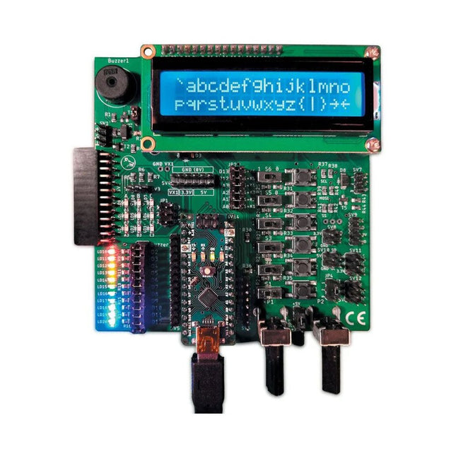
Elektor Labs Elektor Arduino Nano MCCAB Training Board
The Elektor Arduino Nano MCCAB Training Board contains all the components (incl. Arduino Nano) required for the exercises in the "Microcontrollers Hands-on Course for Arduino Starters", such as light-emitting diodes, switches, pushbuttons, acoustic signal transmitters, etc. External sensors, motors or assemblies can also be queried or controlled with this microcontroller training system. Specifications (Arduino Nano MCCAB Training Board) Power Supply Via the USB connection of the connected PC or an external power supply unit (not included) Operating Voltage +5 Vcc Input Voltage All inputs 0 V to +5 V VX1 and VX2 +8 V to +12 V (only when using an external power supply) Hardware periphery LCD 2x16 characters Potentiometer P1 & P2 JP3: selection of operating voltage of P1 & P2 Distributor SV4: Distributor for the operating voltagesSV5, SV6: Distributor for the inputs/outputs of the microcontroller Switches and buttons RESET button on the Arduino Nano module 6x pushbutton switches K1 ... K6 6x slide switches S1 ... S6 JP2: Connection of the switches with the inputs of the microcontroller Buzzer Piezo buzzer Buzzer1 with jumper on JP6 Indicator lights 11 x LED: Status indicator for the inputs/outputs LED L on the Arduino Nano module, connected to GPIO D13 JP6: Connection of LEDs LD10 ... LD20 with GPIOs D2 ... D12 Serial interfacesSPI & I²C JP4: Selection of the signal at pin X of the SPI connector SV12 SV9 to SV12: SPI interface (3.3 V/5 V) or I²C interface Switching output for external devices SV1, SV7: Switching output (maximum +24 V/160 mA, externally supplied) SV2: 2x13 pins for connection of external modules 3x3 LED matrix(9 red LEDs) SV3: Columns of the 3x3 LED matrix (outputs D6 ... D8) JP1: Connection of the rows with the GPIOs D3 ... D5 Software Library MCCABLib Control of hardware components (switches, buttons, LEDs, 3x3 LED matrix, buzzer) on the MCCAB Training Board Operating Temperature Up to +40 °C Dimensions 100 x 100 x 20 mm Specifications (Arduino Nano) Microcontroller ATmega328P Architecture AVR Operating Voltage 5 V Flash Memory 32 KB, of which 2 KB used by bootloader SRAM 2 KB Clock Speed 16 MHz Analog IN Pins 8 EEPROM 1 KB DC Current per I/O Pins 40 mA on one I/O pin, total maximum 200 mA on all pins together Input Voltage 7-12 V Digital I/O Pins 22 (6 of which are PWM) PWM Output 6 Power Consumption 19 mA Dimensions 18 x 45 mm Weight 7 g Included 1x Elektor Arduino Nano Training Board MCCAB 1x Arduino Nano
€ 69,95
Best Price
-

Elektor Digital Mikrocontroller 3 (PDF)
Mikrocontroller 3 (PDF)
€ 16,90
Members: € 15,21
-

Elektor Digital Grundlagen und Schaltungen der Stromversorgungstechnik (PDF)
Aus der Reihe "Stromversorgung ohne Stress" (Band 1) 2., überarbeitete und erweiterte Auflage Eines haben alle elektronischen Schaltungen und Geräte gemeinsam: Ihre Funktion hängt von der Stromversorgung ab. Deshalb muss dieser Baugruppe besondere Aufmerksamkeit gewidmet werden. Dieses Buch beinhaltet Grundlagen und Schaltungen der Stromversorgungstechnik für elektronische Geräte aus der Praxis. Dem aktuellen Trend folgend behandelt der Autor insbesondere die mobile Stromversorgungstechnik sowie die Schaltnetzteiltechnik. Dabei wird berücksichtigt, dass Stromkonstanter gegenüber Spannungskonstantern zunehmend an Bedeutung gewinnen. Im Buch finden sich die notwendigen Grundlagen zum Bau eigener Stromversorgungsgeräte und -baugruppen. Außerdem enthält es ganz praktische Anwendungsbeispiele, z. B. für den Ersatz defekter Netztransformatoren, für die mobile Stromversorgung auf Fahrradtouren oder für den Betrieb von LEDs. Diese zweite Auflage wurde gründlich überarbeitet, Fehler wurden behoben und einige Ergänzungen vorgenommen. Der Autor Franz Peter Zantis ist Energieanlagenelektroniker und Ingenieur der Nachrichtentechnik. In einem Forschungsprojekt hat er sich ausführlich mit der Stromversorgung eigensicherer Geräte auseinandergesetzt und zahlreiche Beiträge zum Thema Schaltnetzteile veröffentlicht.
€ 32,80
Members: € 29,52
-

Elektor Digital Elektor Mei/Juni 2024 (PDF)
Elektor GREEN en GOLD leden kunnen deze uitgave hier downloaden. Nog geen lid? Klik hier om een lidmaatschap af te sluiten. STM32 Wireless Innovation Design Contest: de winnaars In-circuit LC-meteroverwegingen bij een prototype AmpVolt: een modulaire DC-vermogensmeter (deel 1)meet gelijkstroom en energieverbruik tot 50 V en 5 A embedded world 2024 Elektronische apparatuur reparerentools, technieken en tips Alle begin... - NL TRANSLATION...gaat verder met de opamp-theorie Eenvoudige DDS-signaalgeneratordirecte digitale synthese in zijn puurste vorm Sparkplug bekekenspecificatie voor MQTT-data De CRTCvreemde onderdelen Radargestuurde verlichtingautomatische trapverlichting met personendetectie Digitale waterpas en actieve stroboscoop voor draaitafelsregel je platenspeler perfect af met dit alles-in-één tool Onderzoek naar de uitdagingen en commerciële waarde van open source-elektronica (2) Ronde M12-connector met A-coderingvoorkeursoplossing voor industriële toepassingen Het Arduino-Inside Measurement Labeen 8-in-1 test- en meetinstrument voor de elektronica-werkbank Frequentie-, fase- en impedantieanalyse met een geluidskaartvoor frequenties van 100 Hz tot 90 kHz Zuurgraad meten met de Arduino UNO R4controleer de waterkwaliteit Uit het leven gegrepenpangpongbilletjes-lanceermachine FNIRSI 1014D digitale geheugenoscilloscoopgoede prestaties voor weinig geld 2024: een AI-odysseeobjectdetectie aan de praat krijgen 10MHz-referentiegeneratorzeer nauwkeurig, met verdeler en galvanische isolatie Project-update #2: ESP32-gebaseerde energiemeterenkele verbeteringen Project 2.0correcties, updates en brieven van lezers Een vraaggesprek met Eben Upton, CEO van Raspberry Pide Raspberry Pi 5 – en daarna
€ 9,95
-

Elektor Digital Elektor Septembre/Octobre 2021 (PDF)
VOYAGE DANS LES RÉSEAUX NEURONAUX (1ÈRE PARTIE)Les neurones artificiels TEST DE PRÉCONFORMITÉ CEM POUR UN PROJET ALIMENTÉ EN COURANT CONTINUPartie 1 : RSIL double continu CHARGE ÉLECTRONIQUE EN CC ET CAJusqu?à 400 V et 10 A (crête) DÉMARRER EN ÉLECTRONIQUE (9)N'ayez pas peur du choc... un peu de « self control » suffit ! TRAITEMENT D'IMAGES AVEC LE MODULE JETSON NANO DE NVIDIA (1ÈRE PARTIE)Matériel et logiciel ZOOM SUR LES TRANSFORMATEURS SECTEURComportement transitoire à l?allumage et l?extinction « YES WE CAN » AVEC PICAN 3Module de bus CAN pour le Raspberry Pi 4 CENTRALE SOLAIRE SUR BALCONUn investissement vite amorti PRISE DE VUE ET DIFFUSION VIDÉO EN CONTINU AVEC UN RASPBERRY PI 4La caméra Raspberry Pi HQ en action UTILISATION D?ÉCRANS DANS LES PROJETS RASPBERRY PIExtrait : écrans à diodes électroluminescentes organiques (OLED) PROPELLER 2 DE PARALLAX (4)Envoi de chaînes de caractères 60 ANS D?ELEKTORRegard sur septembre DANS L?ANTRE DE?Menno van der Veen et de ses tubes amplificateurs CIRCUITS HYBRIDES ROSE DES VENTS AVEC LE CAPTEUR GY-271Ou pourquoi il faut faire des huit pour calibrer un capteur MESUREZ VOTRE EMPREINTEÉlectronique et émissions de gaz à effet de serre THERMOSTAT CONNECTÉ À ESP32Conservez votre vin à la bonne température ! LÉVITATION MAGNÉTIQUE, VERSION NUMÉRIQUEComparateur analogique remplacé par un ESP32 Pico ULTIMATE ARDUINO UNO HARDWARE MANUAL - FR TRANSLATIONExtrait : chargeur d?amorçage du microcontrôleur principal MICROPYTHON POUR L'ESP32 ET SES COPAINSPartie 2 : piloter facilement les écrans matriciels CARTE MADMACHINE SWIFTIOUn langage récent pour du matériel tout nouveau SUR LE VIFPassions incertaines HEXADOKUCasse-tête pour elektorniciens
€ 10,95


