
Search results for "elektor or membership or de"
-

Elektor Digital Elektor Janvier/Février 2022 (PDF)
COMMANDE DE MOTEURS : LES PONTS EN HIntroduction aux moteurs CC, pas à pas et sans balais L?ÉQUIPE D?ELEKTOR LABNotre approche, nos outils préférés et plus encore RASPBERRY PI COMME TÉLÉCOMMANDE KVMTest du logiciel Pi-KVM IQAUDIO CODEC ZEROCarte son au format Raspberry Pi Zero LE PROJET PIKVM ET SES ENSEIGNEMENTSEntretien avec Maxim Devaev VÉHICULE AUTONOME AVEC LIDAR 2DUn ESP32 Pico interprète les données du lidar LE RASPBERRY PI ZERO 2 W PASSE AU QUADRICOEUR NOTES DU FORUM MONDIAL DE L?ÉLECTRONIQUE ÉTHIQUE 2021 COMMANDE DE MONTEURLa commande des moteurs devient simple MOTEURS ÉLECTRIQUES DE GRANDE TAILLEPrincipes de base et informations utiles PRISE EN MAIN DU MICROCONTRÔLEUR ESP32-C3 RISC-V PROTÉGEZ-VOUS ET PROTÉGEZ LES AUTRES !Interrupteur général pour paillasse (DIY) CRÉATION D?INTERFACES GRAPHIQUES EN PYTHON ÈME 2Mon nom n?est pas Bond GAGNANTS DU CONCOURS FAST FORWARD 2021 DU SALON PRODUCTRONICA TESTEUR DE SERVO POLYVALENTVérification du comportement en l?absence de fiche technique MODBUS SANS FIL (PARTIE 2)Logiciel de la carte Modbus TCP sans fil VOYAGE DANS LES RÉSEAUX NEURONAUX (3E PARTIE)Les neurones pratiques DANS L?INTIMITÉ D?UN PROCESSEUR OPEN SOURCEExtrait : résultats des FPGA Lattice et Xilinx DÉMARRER EN ÉLECTRONIQUE... (10)Toujours la bobine, mais avec ses applications pratiques dans l?audio. PROJET 2.0Corrections, mises à jour et courriers des lecteurs DE LA COULEUR AUSONComment exploiter un capteur de couleurs avec l?I2C SOURCEMÈTRE BATTLAB-ONEMesurer et optimiser la durée de vie des batteries des appareils IdO TRACEUR DE FUITES À LA TERRE SIMPLEMesure de l?isolation du secteur PAUVRETÉ ET ÉLECTRONIQUEQuand le courant économique passe mal HEXADOKUcasse-tête pour elektorniciens
€ 10,95
-

Elektor Digital Elektor Juli/Augustus 2023 PDF (NL)
Elektor GREEN en GOLD leden kunnen deze uitgave hier downloaden.Nog geen lid? Klik hier om een lidmaatschap af te sluiten. Kiesschijftelefoon als afstandsbedieningvoor licht kies 1; voor koffie kies 2 GPS-gebaseerde snelheidsmeternooit meer bekeuringen RGB-stroboscoop met Arduinokleurige toepassing van een nuttig instrument Draadloze nooddrukknopmeer veiligheid met LoRa Alle begin......volgt de emitter Vrij te kiezen onafhankelijke hystereseniveaus voor comparatorenmet simulaties, spreadsheets en algebra Impedantie-analyzer op basis van een ESP32simpel, weinig onderdelen en goedkoop! Oost West Lab Bestzelfbouw moet gestimuleerd! Het MCCAB Arduino Nano Training Boardalle hardware voor de “Microcontrollers Hands-On Course” Uit het leven gegrepenmodern luddisme Sensor-ABC: de DS18B20 temperatuursensoraansluiting op de 1-Wire bus Gaan Matter en Thread het Smart Home redden?nieuwe standaarden om het slimme huis te vereenvoudigen Een kwestie van samenwerkingontwikkelen met het Thing Plus Matter Board en Simplicity Studio Elektor IIIIinfographicIoT en sensoren Matter, ExpressLink, Rainmaker – waar hebben we het over?vraaggesprek met Amey Inamdar van Espressif De juiste keuze van microcontroller-ontwikkelkitsvoor IoT- en IIoT-toepassingen Condensatoren gedragen zich niet altijd capacitief! Een NTP-klok met CircuitPythonwaarom zou je deze programmeertaal gebruiken? Bouw een cool IoT-display'met de Phambili Newt De doppler-bewegingssensor HB100theorie en praktijk Een gids voor puristisch programmeren (deel 1)voor STM32 en andere controllers Siglent SDM3045X-multimeter Microprocessoren voor embedded systemenvreemde onderdelen Microcontroller-documentatie verklaarddeel 3: blokschema’s en meer Low-power LoRa-weerstationbouw zelf een weerstation met een groot bereik Transverter voor de 70cm-band Klimaat aan ingenieurssnelheid is geboden! Hexadoku
€ 9,95
-
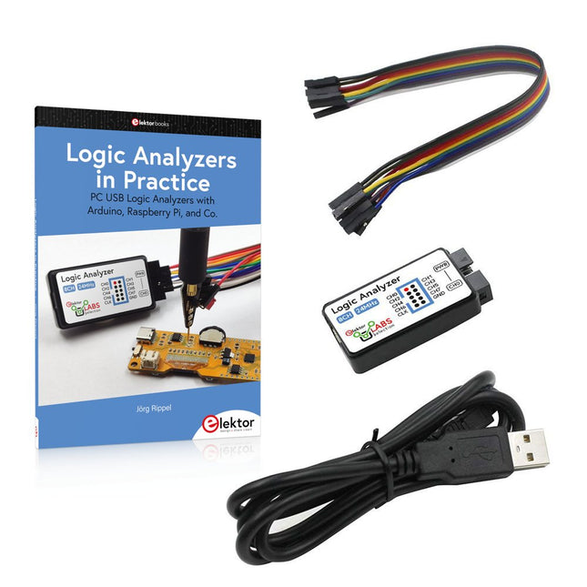
Elektor Bundles Logic Analyzers in Practice (Bundle)
Book: Logic Analyzers in Practice Step-by-step instructions guide you through the analysis of modern protocols such as I²C, SPI, UART, RS-232, NeoPixel, WS28xx, HD44780 and 1-Wire. With the help of numerous experimental circuits based on the Raspberry Pi Pico, Arduino Uno and the Bus Pirate, you will learn the practical application of popular USB logic analyzers. All the experimental circuits presented in this book have been fully tested and are fully functional. The necessary program listings are included – no special programming or electronics knowledge is required for these circuits. The programming languages used are MicroPython and C along with the development environments Thonny and Arduino IDE. This book uses several models of flexible and widely available USB logic analyzers and shows the strengths and weaknesses of each price range. You will learn about the criteria that matter for your work and be able to find the right device for you. Whether Arduino, Raspberry Pi or Raspberry Pi Pico, the example circuits shown allow you to get started quickly with protocol analysis and can also serve as a basis for your own experiments. After reading this book, you will be familiar with all the important terms and contexts, conduct your own experiments, analyze protocols independently, culminating in a comprehensive knowledge set of digital signals and protocols. USB Logic Analyzer (8-ch, 24 MHz) This USB Logic Analyzer is an 8-channel logic analyzer with each input dual purposed for analog data recording. It is perfect for debugging and analyzing signals like I²C, UART, SPI, CAN and 1-Wire. It operates by sampling a digital input connected to a device under test (DUT) at a high sample rate. The connection to the PC is via USB. Specifications Channels 8 digital channels Maximum sampling rate 24 MHz Maximum input voltage 0 V ~ 5 V Operating temperature 0°C ~ 70°C Input impedance 1 MΩ || 10 pF Supported protocols I²C, SPI, UART, CAN, 1-Wire, etc. PC connection USB Dimensions 55 x 28 x 14 mm Downloads Software This bundle contains: Book 'Logic Analyzers in Practice' (normal price: €35) USB Logic Analyzer (8-ch, 24 MHz) (normal price: €20) USB Cable Jumper Wire Ribbon Cable
€ 54,95€ 44,95Best Price
-

Elektor Publishing SDR mit HackRF One & HackRF Pro
Programmieren mit GNU Radio HackRF ist eine Open-Source-Entwicklung von Great Scott Gadgets und dient als vielseitiges Frontend für Software Defined Radio (SDR). Mit HackRF One und dem Nachfolger HackRF Pro lassen sich eigene SDR-Anwendungen entwickeln, leistungsfähige Empfänger und Sender aufbauen sowie anspruchsvolle Aufgaben der HF-Messtechnik realisieren. Dieses Buch eröffnet einen praxisnahen Einstieg in die Welt des Software Defined Radio. Schritt für Schritt zeigt der Autor, wie sich mit HackRF leistungsfähige SDR-Projekte umsetzen lassen – von den Grundlagen der HF-Technik bis hin zu anspruchsvollen Anwendungen mit GNU Radio. Neben dem Umgang mit SDR Sharp (SDR#), RadioConda und GNU Radio vermittelt das Buch auch die Grundlagen moderner digitaler Signalverarbeitung. Zahlreiche Experimente und leicht nachvollziehbare Praxisbeispiele führen durch Themen wie AM-, FM- und SSB-Empfang, digitale Filter, Kurzwelle, Amateurfunk, Messsender und eigene HF-Projekte bis 6 GHz. Ob Maker, Funkamateur, Elektronik-Enthusiast oder SDR-Einsteiger – dieses Buch vermittelt fundiertes Wissen, praxisnahe Anwendungen und die Motivation, die Möglichkeiten moderner SDR-Technik kreativ auszuschöpfen.
€ 24,90
Best Price
-

Elektor Digital Elektor 09-10/2020 als PDF (DE)
Elektor 09-10/2020 als PDF (DE)
€ 11,90
-
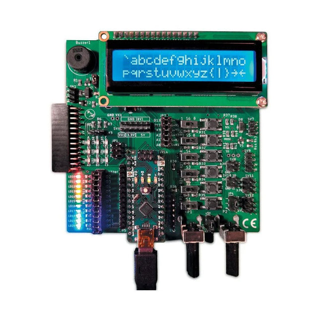
Elektor Labs Elektor Arduino Nano MCCAB Training Board
The Elektor Arduino Nano MCCAB Training Board contains all the components (incl. Arduino Nano) required for the exercises in the "Microcontrollers Hands-on Course for Arduino Starters", such as light-emitting diodes, switches, pushbuttons, acoustic signal transmitters, etc. External sensors, motors or assemblies can also be queried or controlled with this microcontroller training system. Specifications (Arduino Nano MCCAB Training Board) Power Supply Via the USB connection of the connected PC or an external power supply unit (not included) Operating Voltage +5 Vcc Input Voltage All inputs 0 V to +5 V VX1 and VX2 +8 V to +12 V (only when using an external power supply) Hardware periphery LCD 2x16 characters Potentiometer P1 & P2 JP3: selection of operating voltage of P1 & P2 Distributor SV4: Distributor for the operating voltagesSV5, SV6: Distributor for the inputs/outputs of the microcontroller Switches and buttons RESET button on the Arduino Nano module 6x pushbutton switches K1 ... K6 6x slide switches S1 ... S6 JP2: Connection of the switches with the inputs of the microcontroller Buzzer Piezo buzzer Buzzer1 with jumper on JP6 Indicator lights 11 x LED: Status indicator for the inputs/outputs LED L on the Arduino Nano module, connected to GPIO D13 JP6: Connection of LEDs LD10 ... LD20 with GPIOs D2 ... D12 Serial interfacesSPI & I²C JP4: Selection of the signal at pin X of the SPI connector SV12 SV9 to SV12: SPI interface (3.3 V/5 V) or I²C interface Switching output for external devices SV1, SV7: Switching output (maximum +24 V/160 mA, externally supplied) SV2: 2x13 pins for connection of external modules 3x3 LED matrix(9 red LEDs) SV3: Columns of the 3x3 LED matrix (outputs D6 ... D8) JP1: Connection of the rows with the GPIOs D3 ... D5 Software Library MCCABLib Control of hardware components (switches, buttons, LEDs, 3x3 LED matrix, buzzer) on the MCCAB Training Board Operating Temperature Up to +40 °C Dimensions 100 x 100 x 20 mm Specifications (Arduino Nano) Microcontroller ATmega328P Architecture AVR Operating Voltage 5 V Flash Memory 32 KB, of which 2 KB used by bootloader SRAM 2 KB Clock Speed 16 MHz Analog IN Pins 8 EEPROM 1 KB DC Current per I/O Pins 40 mA on one I/O pin, total maximum 200 mA on all pins together Input Voltage 7-12 V Digital I/O Pins 22 (6 of which are PWM) PWM Output 6 Power Consumption 19 mA Dimensions 18 x 45 mm Weight 7 g Included 1x Elektor Arduino Nano Training Board MCCAB 1x Arduino Nano
€ 69,95
Best Price
-

Elektor Digital Build Your Own Software-Defined Radio (E-book)
Practical Guide to Modular RF Design Build Your Own Software-Defined Radio combines RF circuitry with hardware programming and PC-based signal processing. The e-book presents a modular approach to building a complete SDR system using RF Bricks – from the mechanical framework and RF modules to measurement tools, PC software, and FPGA implementations. Practical explanations guide readers through real signal paths, construction steps, and measurement routines, linking hardware and software into a flexible SDR platform. Key topics include: Mechanical setup: RF Brick template, chassis, and 19-inch module carrier Bridges: USB isolator, I²C level shifter, I²C power switch, and practical examples Signal-chain design with RF Bricks: antennas, band filters, NanoVNA work, preamplifiers, PLLs, demodulators, direct-conversion chains, multiband options, and narrowband bricks RF measurement Bricks: single- and dual-tone sources, NPR methods, noise generators, notch filters, broadband amplifiers, and impedance bridges Useful accessories: ATU-100 tuner, X-Phase QRM eliminator, and firmware notes PC host software: SoapyAudio adjustments, GQRX, SDR++, and added functionality GnuRadio elements: control blocks, SSB demodulation, GUI components, messaging, and filter handling FPGA-based SDR: VHDL, toolchains, ADC/DAC blocks, oversampling, and a complete SSB/CW signal chain With its modular structure and detailed working examples, this e-book offers a practical path to building and extending modern SDR systems. Downloads Software
€ 32,95
Members: € 29,66
-

Elektor Digital Mikrocontroller 2 (PDF)
Mikrocontroller 2 (PDF)
€ 16,90
Members: € 15,21
-

Elektor Digital Elektor Special: Sensoren für Wetter und Umwelt (PDF)
Bauen Sie Ihre perfekte Wetterstation oder forschen Sie zusammen mit der ganzen Welt an Umweltdaten. Mit vielen praktischen Projekten für Arduino, Raspberry Pi, NodeMCU, ESP32 und weiteren Developmentboards. Wetterstationen erfreuen sich seit Jahrzehnten großer Beliebtheit. Ob in aktuellen oder längst eingestellten Elektronik-Magazinen – regelmäßig finden sich Beiträge zum Eigenbau einer Wetterstation. Im Laufe der Jahre wurden diese Systeme immer ausgefeilter und können heute nahtlos in das Smart Home integriert werden. Allerdings erfordert dies oft die Bindung an einen (teuren) Markenhersteller, der sämtliche Komponenten abdeckt. Mit Ihrer eigenen Wetterstation können Sie jedoch mühelos mithalten – und sogar Messwerte erfassen, die kommerzielle Geräte nicht bieten. Dabei kommt der Spaß nicht zu kurz: Sie erweitern spielerisch Ihr Wissen über Elektronik, moderne Mikrocontroller-Developmentboards und Programmiersprachen. Schon für weniger als zehn Euro können Sie erste Umweltdaten erfassen und Ihr System Schritt für Schritt mit wachsendem Interesse weiter ausbauen. Aus dem Inhalt: Wind und Wetter auf der Spur Wetterdisplay mit OpenWeatherMap und Vakuum-Fluoreszenzanzeige Flüchtige organische Verbindungen in der Atemluft Mit MQ-Sensoren arbeiten: Kohlenmonoxid messen – geruchlos aber extrem giftig CO2-Ampel mit ThingSpeak-IoT-Anbindung Ein Gießautomat für Ihre Pflanzen Gutes Raumklima: Temperatur und Luftfeuchtigkeit sind wichtige Kriterien Schickes Thermometer mit alter Röhrentechnik Nostalgisches Wetterhäuschen für die ganze Familie Luftdruck und Temperatur genau messen Sonnenbrand-Warngerät DIY-Sensor für die Sonnenscheindauer Das Smartphone zeigt’s an: Nebel oder klare Sicht? Erdbeben erkennen Pegelstände von Gewässern und Behältern pH-Wert von Gewässern bestimmen Radioaktive Strahlung erkennen Mit GPS wissen Sie weltweit, wo ihr Sensor ist Logdateien mit Zeitstempel auf SD-Karten speichern LoRaWAN, The Things Network und ThingSpeak LoRaWAN-Gateway für TTN betreiben Mega-Display mit Wettervorhersage
€ 11,90
Members: € 10,71
-

Elektor Digital Practical Microcontroller Cryptography (E-book)
From Simple Ciphers to Secure Systems Understanding how to apply cryptography on modern microcontrollers is essential for building secure, reliable, and trustworthy systems. This book explains cryptography in the context of embedded hardware, from classical ciphers that illustrate core principles to modern techniques such as AES for practical high-security applications. By combining mathematical theory with real-world microcontroller implementations, readers learn not only how cryptography works, but also how to implement it effectively on systems with limited processing power and memory. The book is intended for students starting out in cryptography, hobbyists securing personal projects, and engineers looking for a structured guide to embedded security. The book covers these key topics in applied cryptography: Classical ciphers on Arduino Uno and Raspberry Pi Pico, with full programs: Spartan Scytale, Hebrew Atbash, Caesar, ROT13, Alberti Disk, Vigenère, Affine, Polybius, Playfair, Beaufort, Ottoman Codebook, and One-Time Pad. Hacking classical ciphers using microcontrollers, with examples. Pseudo-random (PRNG) and true random number generation (TRNG) on microcontrollers. Symmetric-key cryptography with full programs: DES and AES-128/256. Memory and speed constraints of cryptography on microcontrollers. Asymmetric cryptography: public/private keys, digital signatures, key distribution and derivation (KDF), RSA, and SHA-256 implementations. A complete secure communication program using RSA and AES-256. A glossary of commonly used cryptography terms.
€ 29,95
Members: € 26,96
-

Elektor Labs Elektor Low-Noise Lab Power Supply
The Elektor Low-Noise Lab Power Supply is a fully analogue, adjustable, medium-power symmetrical bench supply that contains no switching or digital components. It provides an output voltage adjustable between 0 V and ±22 V, and an output current adjustable from 0 A to 1 A. Because it avoids any form of switching circuitry, the design delivers extremely low noise. To display both output voltages and currents, four miniature moving-coil panel meters are used. Most modern laboratory power supplies and AC adapters employ switch-mode techniques. Even the best examples inevitably exhibit high-frequency ripple and other switching artefacts on their output, which can interfere with the testing of sensitive analogue circuits and disturb low-level measurements. To overcome this, the concept here is a completely analogue power supply. Although less efficient than its switch-mode counterparts, the reduced efficiency is of little importance for test-bench use and ensures cleaner, more reliable measurement results. Because many analogue circuits require a symmetrical supply, this design delivers positive and negative output voltages of equal magnitude. A small amount of adjustment is available to compensate for any imbalance. Naturally, a variable current-limit function is also included. The kit includes the components required to build the power supply, except for the transformers. Specifications Output Voltage 0…+22 V, 0, −22 V Output Current 0…+1 A, 0…−1 A Noise −85 dBV, (at 0.95 A/20 V, B = 22 kHz) −84 dBV (at 0.95 A/20 V, B > 500 kHz) Ripple 50 µVRMS (at 950 mA/20 V, B = 22 kHz, mainly 100 Hz component) Included 3x PCBs: Regulator (PCB-1), Mains Filter (PCB-2) and Transformer (PCB-3) All the components except the AC transformers 4x moving-coil meters Additional parts for wiring (wires, banana sockets, IEC Power entry module, etc.) Not included The three AC transformers An enclosure Parts List For the Regulator PCB (240386-1) Resistors (250 mW, 1%) R1 = 12 Ω R2, R8, R37, R62 = 1 MΩ R3, R7, R10, R13, R17, R20, R22, R30, R35, R42, R45, R47, R55, R60 = 100 Ω, 600 mW R4, R5 = 4.7 kΩ R6 = 100 kΩ R9, R12, R14, R36, R38, R39, R61, R63, R66, R72, R78, R79 = 10.0 kΩ, 600 mW R11 = 9.76 kΩ, 600 mW R15, R40 = 44.2 kΩ, 600 mW R16, R41, R77 = 1 kΩ R18, R43 = 1.5 kΩ, 1 W, 5% R19, R44 = 470 Ω, 1 W, 5% R21, R46 = 330 Ω, 600 mW R23, R24, R48, R49 = 1.0 Ω, 1 W R25, R50 = 1 kΩ, 1 W, 5% R26, R28, R51, R53 = 1.000 kΩ 0.1%, 15 ppm/C R27, R29, R52, R54 = 10.00 kΩ 0.1%, 15 ppm/C R31, R56 = 1.2 kΩ, 1 W, 5% R32, R57 = 47 kΩ R33, R58 = 270 Ω R34, R59 = 27 kΩ R64, R69 = 12.0 kΩ R65 = 3.0 kΩ, 600 mW R67, R80 = 470 Ω, 600 mW R68, R70 = 6.8 kΩ, 600 mW R71 = 30.0 kΩ,, 600 mW R73, R74, R75, R76 = 10 MΩ P1, P2, P3 = 10 kΩ, 200 mW, 20%, potentiometer, 1 turns, single, lin., panel mount P4, P5 = 500 Ω, 500 mW, 10%, trimmer, 25 turns, 3296Y-1-501LF Bourns P6, P7 = 10 kΩ, 500 mW, 10%, trimmer, 25 turns, 3296Y-1-501LF Bourns Capacitors C1 = 100 nF, 50 V, 10%, ceramic X7R, LS 5 mm C2, C3, C6, C7, C30 = 10 µF, 63V, 20%, LS 2.5 mm, 3000hours@105°C C4, C5, C8, C9, C13, C14, C18, C19, C23, C24, C28, C29, C31, C32, C38, C39 = 100 nF, 250 V, 10%, PET, LS 7.5 mm C10, C20 = 47 nF, 100 V, 5%, PET, LS 5 mm C11, C21 = 10 nF, 100 V, 5%, PET, LS 5 mm C12, C22 = 220 µF, 35 V, 20%, 0.024 Ω, LS2.5/3.5 mm, Ir 3.4 A, 2000hours@125°C, polymer C15, C25 = 120 µF, 50 V, 20%, ESR 0.02 Ω, Diam. 10 mm max., LS 5 mm C16, C26 = 15 nF, 100 V, 5%, PET, LS 5 mm C17, C27 = 47 nF, 100 V, 5%, PET, LS 5 mm C33, C34 = 22 µF, 50 V, 20%, LS 2 mm, 10000 hours @ 105°C C35, C36, C44, C45 = 1 µF, 100 V, 10%, LS 5 mm, ceramic X7R C37 = 100 uF, 50 V, 20%. LS 3.5 mm C40, C41, C42, C43, C46, C47, C48, C49 = 1000 µF, 50 V, 20%, LS 5/7.5 mm, Ir 3.32 A, 10000hours@105°C, D 16 mm C50, C51, C52, C53 = 47 nF, 100 V, 10%, ceramic X7R, LS 5 mm Inductors L1, L2 = 4.7 µH, 3.2 A, 0.033 Ω, LS 5 mm, RLB0914-4R7ML Bourns L3 = Commom mode choke, 14.5 mH, 3 A, SSRH24NH-30145 Kemet Semiconductors D1, D2, D3, D4, D5, D9, D10, D11, D15 = BAT85, DO-34 D6, D7, D12, D13 = SR560, DO-201AD D8, D14, D16 = 1N4148, DO-35 D17 = Zenerdiode, 5.6 V, 0.5 W, DO-41 D18, D19 = 1N4004, DO-41 D20, D21 D22, D23 = V30100CI-M3/P, dual common cathode, TO-220 D24 = Zener diode, 30 V, 1 W, DO-41 LED1, LED2 = LED, red, T-1 (3 mm) LED3, LED4 = LED, green, T-1 (3 mm) TVS1, TVS2 = BZW50-33B, R6 T1, T2, T4 = BC337.25, TO-92 T3 = NJW0302G, TO-3P T5, T6, T8 = BC327.25, TO-92 T7 = NJW0281G, TO-3P T9 = BD139, TO-126 (SOT-32) IC1 = LM334Z, TO-92 IC2 = LM4040AIZ-5.0/NOPB, TO-92 (TO-226AA-3) IC3, IC4 = OPA2992IDR, SOIC-8 IC5, IC6 = OPA4992IDR, SOIC-14 IC7 = OPA992IDBVR, SOT-23-5 IC8 = LM339N, DIP-14 IC9 = LM317, TO-220 IC10 = LM337, TO-220 Others F1, F2 = 5×20 mm fuse, 1.6 A, fast acting HS1, HS2 = Heatsink MC33271 (for T3/T7), 2.7°C/W, PCB mount, height 63.5 mm K1, K4 = 3-way screw terminal block, LS 3.5 mm, max. 1.5 mm² K2, K3 = 3-way screw terminal block, LS 3.5 mm, max. 1 mm² M1, M3 = Moving coil meter, Range 30 V, type 91C4, 45×45 mm M2, M4 = Moving coil meter, Range 1 A, type 91C4, 45×45 mm² RE1 = Relay DPDT,5V, UA2-5NU Miscellaneous 3× 3-way screw terminal block, LS 3.5 mm, max. 1 mm² (for P1, P2, P3) 4× Pin header, 1×2, vertical, pitch 2.54 mm (for LED1, LED2, LED3, LED4) 4× Pin socket, 1×2, vertical. pitch 2.54 mm (for LED1, LED2, LED3, LED4) 2× Heatsink FK222SA220, 20°C/W, PCB mount (for IC9 & IC10) 2× Mica thermal pad for TO-220, 12×18×0.05 mm (for IC9 & IC10) 2× Insulating bushing IB 6, TO-220 (for IC9 & IC10) 2× Ceramic thermal pad, 23×20×2 mm (for T3 & T7) 2× PCB Fuse Holder, for 5×20 mm fuse, 10 A (for F1, F2) 2× Cover for PCB Fuse Holder, transparent (for F1, F2) 2× 2-way screw terminal block, LS 3.5 mm, max. 1 mm² (for M1 & M3) 2× 2-way screw terminal block, LS 3.5 mm, max. 1.5 mm² (for M2 & M4) 8× M3 solder lug, thickness 0.35 mm (for M1…M4) M4 solder lug, thickness 0.35 mm (to connect 4 mm banana connectors) Screened cable, 1 pair, 2×24 AWG/0.22 mm², 1 m (for P1, P2 & P3) IC socket, DIP, 14 contacts (for IC8) M3 washer, plain, steel M3 screw, 16 mm, steel, pan head M3 nut M3 spring washer 50 mm M3 standoff, steel, male-female 12 mm M3 standoff, steel, male-female 10 mm M3 standoff, steel, male-female M3 screw, 8 mm, steel, pan head For the Mains Fiter PCB (240386-2) Resistor R1 = 220 kΩ, 1 W, 500 V, 5% Capacitors C1, C2 = 470 nF, 305 VAC, Class X2, 11 × 27 mm max., LS 15/22.5 mm C3, C4, C5, C6 = 2.2 nF, 300 VAC, Class Y2, 13 × 4 mm, LS 10 mm, PP Inductors L1, L2 = Common-mode choke, 6.8 mH, 1.7 A, TDK B82732R2172B030 Semiconductor MOV1 = TVS varistor, 300 VAC, S14K300 (230 VAC, B72214S0301K101) and SK14K150 (150 VAC, B72214S0151K101) Others K1, K2 = 3-way screw terminal block, LS 7.62 mm F1 = Time-delay fuse, 0.5 A (230 VAC) or 1 A (115 VAC) Miscellaneous 1× Fuse holder, 5×20 mm, 10 A, 500 VAC 1× Transparent fuse cover 4× 10 mm M3 standoff, steel, male–female 4× M3 screw, 8 mm, steel, pan head 4× M3 nut For the Transformer PCB (240386-3) Resistors R1, R2 = 2.7 kΩ, 600 mW, 1% R3 = 10.0 kΩ, 600 mW, 1% Capacitor C1 = 220 µF, 50 V, 20%, Ø10 mm, LS 5 mm, 4000 h @ 105°C Transformers (not included in this kit!) TR1, TR2, TR3 = 2×7 V, 25 VA, PCB-mounted toroid, 70060K Talema Semiconductors D1–D4 = 1N4148, DO-35 D5, D6 = 1N4004, DO-41 D7 = Zener 5.6 V, 1.3 W, DO-41 LED1 = LED, red, T-1 (3 mm) IC1, IC2 = MOC8021M, CTR ≥ 1000%, DIP-6 Others F1, F2, F3 = 160 mA time-delay fuse (230 VAC) or 315 mA time-delay fuse (115 VAC) K1 = 2-way screw terminal block, LS 7.62 mm K2 = 3-way screw terminal block, LS 3.5 mm, max 1.5 mm² K3, K4 = 3-way screw terminal block, LS 3.5 mm, max 1 mm² RE1, RE2 = Relay DPDT, 5 A/250 VAC / 24 VDC Miscellaneaous 1× Pin header 1×2, pitch 2.54 mm + matching socket for LED1 3× Fuse holder 5 × 20 mm, 10 A, 500 VAC + transparent cover 3× M4 screw, 8 mm, pan head + washer for TR1-TR3 8× M3 screw, 8 mm, pan head + nut + washer 8× 10 mm M3 standoff, steel, male–female 2× IC socket, DIP-6 for IC1 & IC2 Additional Parts 1 m red insulated wire, stranded, 1.5 mm² 0.5 m blue insulated wire, stranded, 1.5 mm² 0.5 m black insulated wire, stranded, 1.5 mm², 0.5 m 2 m red insulated wire, stranded, D 0.56 mm (0.25 mm²) 2 m black insulated wire, stranded, D 0.56 mm (0.25 mm²) 0.5 m Multicore Cable, Flexible, 3 Core, 0.75 mm² (24 x 0.2 mm) Red banana socket Black banana socket Blue banana socket Green banana socket IEC Power Entry Module with switch, IEC C14 3 crimp terminals, FASTON, 4.75 x 0.81 mm 3 knobs Links Elektor Labs JumpStarter Page Article (Part 1) Article (Part 2)
€ 249,00
Best Price
-

Elektor Publishing Les oscilloscopes anciens & modernes pour les débutants
Ce qui se passe en électronique est par définition invisible à l'oeil nu. L'instrument qui permet précisément de rendre visibles les signaux électriques, celui par le truchement duquel les effets de l'électronique se manifestent à nous, c'est l'oscilloscope. Hélas, quand on commence à faire de l'électronique, c'est souvent sans oscilloscope. Et l'on en est réduit à tâtonner, aussi bien physiquement que mentalement. Le jour où l'on goûte à la visualisation des signaux sur un écran, c'est une révélation. Plus personne ne souhaite se priver de cet enchantement. Pas de retour en arrière. En électronique, si l'on veut progresser dans le plaisir et dans la compréhension, il faut un oscillo. Commence alors une période d'interrogation : comment choisir ? Et à peine cette question-là aura-t-elle trouvé sa réponse, il en viendra une ribambelle d'autres que l'on peut résumer en une seule : comment se servir de l'oscilloscope de telle sorte que ce qu'il affiche corresponde bien à la réalité des signaux ? Dans ce livre, Rémy Mallard, répond clairement à ces questions. Il donne aussi de nombreuses informations pour aider son lecteur à élucider lui-même de nouveaux mystères qui ne manqueront pas de surgir. Ceux qui le connaissent déjà comme l'auteur d'un livre sur l'électronique dont le titre est un programme à lui tout seul : L'électronique pour les débutants qui sèchent les cours mais soudent sans se brûler les doigts, ainsi que d'un livre d'initiation à la programmation des microcontrôleurs PIC, savent qu'ils trouveront ici un ouvrage utile, qu'ils rouvriront souvent.
€ 44,95
Members: € 40,46


