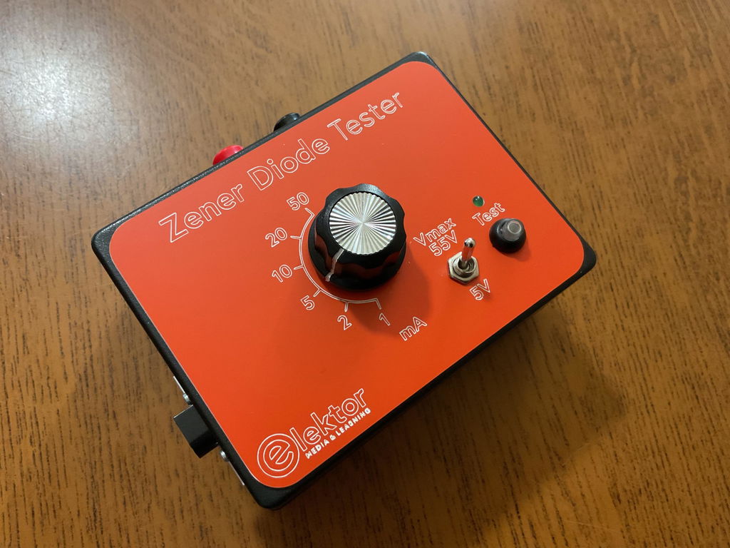
Elektor Zener Diode Tester

Description

The Elektor Zener Diode Tester is essentially a constant-current source that can be switched in steps from 1 to 50 mA. It can be used to test Z-diodes up to a maximum of 54 V. Thanks to a 60-V step-up converter, the device can be powered by the usual 5 to 12 V.

The principle of this tester is straightforward. A Z-diode or other DUT (device under test, such as an LED) is biased by an adjustable current source. The voltage across the DUT can be measured with a multimeter. The voltage of most (small) Z-diodes is specified at a current of 5 mA. Depending on the application, the voltage at other currents can also be of interest. That is why six current settings are available: 1, 2, 5, 10, 20, and 50 mA. LEDs are often specified at a current of 20 mA.

What can be tested is:

  • Whether a Z-diode is defective (short circuit or high impedance).
  • Whether a Z-diode exhibits the correct Z-voltage.
  • How a Z-voltage changes with different currents.
  • What exact voltage is present at an integrated voltage reference.
  • Whether LEDs in a series chain differ in brightness (hence the 20 mA current).
  • What the current gain is for different base currents in (power) transistors.

The kit contains all parts listed in the bill of materials including PCB and enclosure.

Specifications

Supply voltage 5…12 V/2 A (USB-C)
Supply current (Itest = 50 mA) 1.1 A @ 5 V / 412 mA @ 12 V
Selectable currents 1, 2, 5, 10, 20, and 50 mA
Max. test voltage >54 V @ Itest ≥1 mA
Max. output voltage 60 V @ Itest = 0 mA
Voltage limit at 5 V 4.5 V @ Itest = 1 mA / 5.18 V @ Itest = 50 mA
Enclosure dimensions 110 x 82 x 44 mm
PCB size 105.4 x 67.3 mm
Connections 4 mm banana sockets for multimeter
2 mm banana sockets for test clips
USB-C socket for power supply

Included

Resistors

  • R1 = 3.3 kΩ, 600 mW, 1%
  • R2 = 0.15 Ω, 1 W, 5%, LS 12.7 mm, ø 3.5 mm
  • R3, R8 = 180 Ω, 600 mW, 1%
  • R4, R6, R16 = 1 kΩ, 600 mW, 1%
  • R5, R19 = 47 kΩ, 600 mW, 1%
  • R7 = 3.9 kΩ, 1 W, 5%, LS 12.7 mm, ø 3.5 mm
  • R9, R10, R12 = 10 kΩ, 600 mW, 1%
  • R11, R13 = 100 Ω, 600 mW 1%
  • R14 = 249 Ω, 600 mW, 1%
  • R15 = 499 Ω, 600 mW, 1%
  • R17 = 2.49 kΩ, 250 mW, 1%
  • R18 = 4.99 kΩ, 250 mW, 1%

Capacitors

  • C1 = 470 uF / 35 V, 20%, Ir = 1.86 A, ø 12.5 mm, LS 5 mm, ESR = 0.038 Ω (Panasonic EEUTP1V471)
  • C2 = 1 uF / 100 V, 10%, X7R, LS 5 mm
  • C3 = 2.2 nF / 50 V, 10%, X7R, LS 5 mm
  • C4, C7 = 100 nF / 100 V, 10%, X7R, LS 5 mm
  • C5 = 100 uF / 100 V, 20%, ø 14 mm max., LS 5 mm
  • C6 = 1 nF / 100 V, 10%, X7R, LS 5 mm

Inductor

  • L1 = 100 uH, Irms = 2.4 A, Isat = 3.5 A, 0.09 Ω, radial, pitch 2.5/5/10 mm, ø 14 mm max. (Kemet SBC8-101-242)

Semiconductors

  • D1 = MUR120G, DO-41
  • D2, D4 = STPS3150RL, DO-201AD
  • D3 = Z-diode, 18 V, 1.3 W (BZX85C18)
  • D5 = Z-diode, 5.1 V, 0.5 W (1N5231B)
  • LED1 = LED in pushbutton S1
  • LED2 = LED, green, 3 mm
  • IC1 = MC34063, DIP-8
  • IC2 = LM4040BIZ-5.0/NOPB, TO-92 (TO-226AA-3)
  • IC3 = TL051CP, DIP-8
  • T1 = BC327.25, TO-92
  • T2 = STP40NF10L, TO-220
  • T3 = IRF9510PBF, TO-220
  • T4 = 2N7000, TO-92

Others

  • K1, K2, S1, S3 = 2-way screw terminal block, LS 3.5 mm, max. 1.5 mm²
  • connected to K1 = USB-C socket, 30 V/3 A, chassis mounted, wired, 9 x 16 mm
  • connected to K2 = Banana Connector, 2 mm, Socket, 60 VDC, Panel Mount, red (Multicomp 24.102.1)
  • connected to K2 = Banana Connector, 2 mm, Socket, 60 VDC, Panel Mount, black (Multicomp 24.102.2)
  • Test clip, red, 30 VAC/60 VDC (Hirschmann 931467101)
  • Test clip, black, 30 VAC/60 VDC (Hirschmann 931467100)
  • S1 = Pushbutton, panel mount, SPST-NO, 30 DC/100 mA, with red LED
  • S2 = Rotary Switch, 6 position, 2 pole, 30°, 250 V/150 mA
  • S3 = Toggle switch, panel mount, SPDT, solder lugs, 28 VDC
  • T2, T3 = Heat sink, 15°C/W, FK 214 SA-CB
  • Enclosure Hammond 1591XXSSBK, ABS, 110 x 82 x 44 mm
  • Knob for S2, round shaft 6 mm, ø 21 mm, with indicator line (Multicomp CP-LB21-6-6D)
  • 4 x Self-tapping screw #4-1/4", carbon steel, pan head
  • Banana plug, red, 2 mm, 60 VDC (Multicomp 25.205.1)
  • Banana plug, black, 2 mm, 60 VDC (Multicomp 25.205.2)
  • Banana socket, black 4 mm, panel mount
  • Banana socket, red 4 mm, panel mount
  • for LED1, LED2 = Pin header, 1 x 2, vertical, pitch 2.54 mm
  • for LED1, LED2 = Pin socket, 1 x 2, vertical, pitch 2.54 mm
  • for T2, T3 = M3 screw, 10 mm, steel, pan head
  • 2 x M3 washer, plain, steel
  • 4 x M3 nut
  • for IC1, IC3 = DIP-8 socket
  • Wire, black, 0.25 mm² (24 AWG), stranded 14 x 0.15 mm, 1 m
  • Wire, red, 0.25 mm² (24 AWG), stranded 14 x 0.15 mm, 1 m
  • PCB 250772-1 v1.1

Links

Product form

The Elektor Zener Diode Tester is essentially a constant-current source that can be switched in steps from 1 to 50 mA. It... Read more

€ 99,95 € 84,95 (incl. VAT)
Best Price

    Details

    SKU: 21289
    EAN: 7442105136100

    Description

    The Elektor Zener Diode Tester is essentially a constant-current source that can be switched in steps from 1 to 50 mA. It can be used to test Z-diodes up to a maximum of 54 V. Thanks to a 60-V step-up converter, the device can be powered by the usual 5 to 12 V.

    The principle of this tester is straightforward. A Z-diode or other DUT (device under test, such as an LED) is biased by an adjustable current source. The voltage across the DUT can be measured with a multimeter. The voltage of most (small) Z-diodes is specified at a current of 5 mA. Depending on the application, the voltage at other currents can also be of interest. That is why six current settings are available: 1, 2, 5, 10, 20, and 50 mA. LEDs are often specified at a current of 20 mA.

    What can be tested is:

    • Whether a Z-diode is defective (short circuit or high impedance).
    • Whether a Z-diode exhibits the correct Z-voltage.
    • How a Z-voltage changes with different currents.
    • What exact voltage is present at an integrated voltage reference.
    • Whether LEDs in a series chain differ in brightness (hence the 20 mA current).
    • What the current gain is for different base currents in (power) transistors.

    The kit contains all parts listed in the bill of materials including PCB and enclosure.

    Specifications

    Supply voltage 5…12 V/2 A (USB-C)
    Supply current (Itest = 50 mA) 1.1 A @ 5 V / 412 mA @ 12 V
    Selectable currents 1, 2, 5, 10, 20, and 50 mA
    Max. test voltage >54 V @ Itest ≥1 mA
    Max. output voltage 60 V @ Itest = 0 mA
    Voltage limit at 5 V 4.5 V @ Itest = 1 mA / 5.18 V @ Itest = 50 mA
    Enclosure dimensions 110 x 82 x 44 mm
    PCB size 105.4 x 67.3 mm
    Connections 4 mm banana sockets for multimeter
    2 mm banana sockets for test clips
    USB-C socket for power supply

    Included

    Resistors

    • R1 = 3.3 kΩ, 600 mW, 1%
    • R2 = 0.15 Ω, 1 W, 5%, LS 12.7 mm, ø 3.5 mm
    • R3, R8 = 180 Ω, 600 mW, 1%
    • R4, R6, R16 = 1 kΩ, 600 mW, 1%
    • R5, R19 = 47 kΩ, 600 mW, 1%
    • R7 = 3.9 kΩ, 1 W, 5%, LS 12.7 mm, ø 3.5 mm
    • R9, R10, R12 = 10 kΩ, 600 mW, 1%
    • R11, R13 = 100 Ω, 600 mW 1%
    • R14 = 249 Ω, 600 mW, 1%
    • R15 = 499 Ω, 600 mW, 1%
    • R17 = 2.49 kΩ, 250 mW, 1%
    • R18 = 4.99 kΩ, 250 mW, 1%

    Capacitors

    • C1 = 470 uF / 35 V, 20%, Ir = 1.86 A, ø 12.5 mm, LS 5 mm, ESR = 0.038 Ω (Panasonic EEUTP1V471)
    • C2 = 1 uF / 100 V, 10%, X7R, LS 5 mm
    • C3 = 2.2 nF / 50 V, 10%, X7R, LS 5 mm
    • C4, C7 = 100 nF / 100 V, 10%, X7R, LS 5 mm
    • C5 = 100 uF / 100 V, 20%, ø 14 mm max., LS 5 mm
    • C6 = 1 nF / 100 V, 10%, X7R, LS 5 mm

    Inductor

    • L1 = 100 uH, Irms = 2.4 A, Isat = 3.5 A, 0.09 Ω, radial, pitch 2.5/5/10 mm, ø 14 mm max. (Kemet SBC8-101-242)

    Semiconductors

    • D1 = MUR120G, DO-41
    • D2, D4 = STPS3150RL, DO-201AD
    • D3 = Z-diode, 18 V, 1.3 W (BZX85C18)
    • D5 = Z-diode, 5.1 V, 0.5 W (1N5231B)
    • LED1 = LED in pushbutton S1
    • LED2 = LED, green, 3 mm
    • IC1 = MC34063, DIP-8
    • IC2 = LM4040BIZ-5.0/NOPB, TO-92 (TO-226AA-3)
    • IC3 = TL051CP, DIP-8
    • T1 = BC327.25, TO-92
    • T2 = STP40NF10L, TO-220
    • T3 = IRF9510PBF, TO-220
    • T4 = 2N7000, TO-92

    Others

    • K1, K2, S1, S3 = 2-way screw terminal block, LS 3.5 mm, max. 1.5 mm²
    • connected to K1 = USB-C socket, 30 V/3 A, chassis mounted, wired, 9 x 16 mm
    • connected to K2 = Banana Connector, 2 mm, Socket, 60 VDC, Panel Mount, red (Multicomp 24.102.1)
    • connected to K2 = Banana Connector, 2 mm, Socket, 60 VDC, Panel Mount, black (Multicomp 24.102.2)
    • Test clip, red, 30 VAC/60 VDC (Hirschmann 931467101)
    • Test clip, black, 30 VAC/60 VDC (Hirschmann 931467100)
    • S1 = Pushbutton, panel mount, SPST-NO, 30 DC/100 mA, with red LED
    • S2 = Rotary Switch, 6 position, 2 pole, 30°, 250 V/150 mA
    • S3 = Toggle switch, panel mount, SPDT, solder lugs, 28 VDC
    • T2, T3 = Heat sink, 15°C/W, FK 214 SA-CB
    • Enclosure Hammond 1591XXSSBK, ABS, 110 x 82 x 44 mm
    • Knob for S2, round shaft 6 mm, ø 21 mm, with indicator line (Multicomp CP-LB21-6-6D)
    • 4 x Self-tapping screw #4-1/4", carbon steel, pan head
    • Banana plug, red, 2 mm, 60 VDC (Multicomp 25.205.1)
    • Banana plug, black, 2 mm, 60 VDC (Multicomp 25.205.2)
    • Banana socket, black 4 mm, panel mount
    • Banana socket, red 4 mm, panel mount
    • for LED1, LED2 = Pin header, 1 x 2, vertical, pitch 2.54 mm
    • for LED1, LED2 = Pin socket, 1 x 2, vertical, pitch 2.54 mm
    • for T2, T3 = M3 screw, 10 mm, steel, pan head
    • 2 x M3 washer, plain, steel
    • 4 x M3 nut
    • for IC1, IC3 = DIP-8 socket
    • Wire, black, 0.25 mm² (24 AWG), stranded 14 x 0.15 mm, 1 m
    • Wire, red, 0.25 mm² (24 AWG), stranded 14 x 0.15 mm, 1 m
    • PCB 250772-1 v1.1

    Links

    Login

    Forgot password?

    Don't have an account yet?
    Create account