Search results for "pic18"
Elektor Digital Internet of Things (E-BOOK)
The Internet of Things (IoT) is a new concept in intelligent automation and intelligent monitoring using the Internet as the communications medium. The “Things” in IoT usually refer to devices that have unique identifiers and are connected to the Internet to exchange information with each other. Such devices usually have sensors and/or actuators that can be used to collect data about their environments and to monitor and control their environments. The collected data can be processed locally or it can be sent to centralized servers or to the cloud for remote storage and processing. For example, a small device at the size of a matchbox can be used to collect data about the temperature, relative humidity and the atmospheric pressure. This data can be sent and stored in the cloud. Anyone with a mobile device can then access and monitor this data at any time and from anywhere on Earth provided there is Internet connectivity. In addition, users can for example, adjust the central heating remotely using their mobile devices and accessing the cloud.This e-book is written for students, for practising engineers and for hobbyists who want to learn more about the building blocks of an IoT system and also learn how to setup an IoT system using these blocks. Chapter 1 is an introduction to the IoT systems. In Chapter 2, the basic concepts and possible IoT architectures are discussed. The important parts of any IoT system are the sensors and actuators and they are described briefly in Chapter 3. The devices in an IoT system usually communicate with each other and the important aspect of IoT communication is covered in Chapter 4. Chapter 5 proceeds with the features of some of the commonly used development kits. One of these, the Clicker 2 for PIC18FJ manufactured by mikroElektronika, can be used as a processor in IoT systems and its features are described in detail in Chapter 6. A popular microcontroller C language, mikroC Pro for PIC gets introduced in Chapter 7. Chapter 8 covers the use of a click board with the Clicker 2 for PIC18FJ development kit. Similarly, the use of a sensor click board is described as a project in Chapter 9, and an actuator board in Chapter 10. Chapters 11 and 12 cover Bluetooth and Wi-Fi technologies in microcontroller based systems, and the remaining chapters of the book demo the creation of a simple Wi-Fi based IoT system with cloud-based data storage.This e-book has been written with the assumption that the reader has taken a course on digital logic design and has been exposed to writing programs using at least one high-level programming language. Knowledge of the C programming language will be very useful. Also, familiarity with at least one member of the PIC series of microcontrollers (e.g. PIC16 or PIC18) will be an advantage. The knowledge of assembly language programming is not required because all the projects in the book are based on using the C language. If you are a total beginner in programming you can still access the e-book, but first you are advised to study introductory books on microcontrollers.
€ 29,95
Members € 23,96
Elektor Digital GSM/GPRS Projects (E-BOOK)
Based on PIC microcontrollers and Arduino Every mobile phone includes a GSM/GPRS modem which enables the phone to communicate with the external world. With the help of the GSM modems, users can establish audio conversations and send and receive SMS text messages. In addition, the GPRS modem enables users to connect to the internet and to send and receive large files such as pictures and video over the internet. This e-book is aimed for the people who may want to learn how to use the GSM/GPRS modems in microcontroller based projects. Two types of popular microcontroller families are considered in the e-book: PIC microcontrollers, and the Arduino. The highly popular mid-performance PIC18F87J50 microcontroller is used in PIC based projects together with a GSM Click board. In addition, the SIM900 GSM/GPRS shield is used with the Arduino Uno projects. Both GSM and GPRS based projects are included in the e-book. The e-book will enable you to control equipment remotely by sending SMS messages from your mobile phone to the microcontroller, send the ambient temperature readings from the microcontroller to a mobile phone as SMS messages, use the GPRS commands to access the internet from a microcontroller, send temperature readings to the cloud using UDP and TCP protocols and so on. It is assumed that the reader has some basic working knowledge of the C language and the use of microcontrollers in simple projects. Although not necessary, knowledge of at least one member of the PIC microcontroller family and the Arduino Uno will be an advantage. It will also be useful if the user has some knowledge of basic electronics. All project software is available for free download (see 'Attachments/Downloads' section).
€ 22,95
Members € 18,36
Evil Mad Science EiBotBoard (EBB) Driver Board
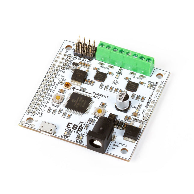
The EiBotBoard ('EBB') is a USB-based dual stepper motor controller board that is useful for many general purpose robotics applications. Originally designed for the EggBot project, it is the 'brain' of all current models of the EggBot, but also of the AxiDraw and WaterColorBot as well. The EBB was designed by Brian Schmalz of Schmalz Haus LLC. It is an open source (in both hardware and software), PIC18F46J50-based motor controller board. Standard features include two Allegro A4983 16X microstepping motor drivers for bipolar steppers. It also has a separate onboard regulator to power up to two hobby servo motors. It is 2.2 x 2.2 inches square (5.6 x 5.6 cm). We are currently shipping version 2.7 of the EBB, which features several improvements for reliability. Version 2.7 uses a standard USB micro connector and has a switch that by default turns off power to the pen-lift servo motor after one minute of inactivity. You can change the timeout duration or disable this feature using the serial command protocol. Specifications Motor driver ICs: Two Allegro A4983 Stepper motor type: Bipolar (2) Step size: Full, 1/2, 1/4, 1/8, 1/16 Motor connectors: Screw terminal USB jack type: Micro-B Power connector: Barrel Jack, 2.1 x 5.5 mm, center positive Voltage input range: 9-25 V DC Output current adjustment: 46 mA to 1.25 A per phase Downloads/Documentation GitHub
€ 69,95
Members € 62,96
LabNation LabNation SmartScope USB Oscilloscope
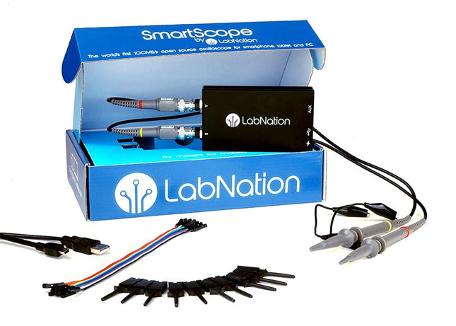
Smartscope is the only scope in the world that runs on all major platforms: Windows, macOS, Linux, Android and iOS (with WiFi bridge). Connect the SmartScope to pretty much any device! Even more, you can get mobile with it: take the SmartScope on the road, thanks to the single-cable connectivity. Everything is going to be intuitive: pointing, pinching and swiping finally replaces the clunky interfaces of old scopes. With the SmartScope you develop your digital interfaces using the 100 MS/s logic analyzer. With this tool you can design any signal you want using Excel, then upload it to the built-in Arbitrary Waveform Generator (AWG). At the end capture the voltage at any point of your design at 100 million times each second. The Software for the support of Windows / macOS) / Linux / Android and Export formats (Excel .csv / Matlab .mat) are given. Features Channel sampled at 100 MHz/s each AC/DC coupling on analog inputs 100% silent 64 Mbit RAM: x10000 zoom Arbitrary Waveform Generator 8 digital inputs at 100 MS/s each 4 digital outputs at 100 MS/s each Externally power your scope in case your mobile can't supply the juice. Specifications Oscilloscope Bandwidth 30 MHz (-3 dB point) Sample rate 2x 100 MS/s Channels 2 Max pre-trigger position 16x full scale Max post-trigger position Full scale Max full voltage scale 10 V/div (±35 V input range) Min full voltage scale 20 mV/div Analog input range -35 V, +35 V Max input peak-to-peak 40 V Signal coupling AC / DC Precision 8 bit Input impedance 1 MΩ // 10 pF Waverforms 200 waveforms/s Data delay to host < 10 ms Sample depth Up to 4 million samples per channel External trigger Yes Logic Analyzer Input channels 8 Input impedance 100 kOhm // 2 pF to GND Sample rate 100 MS/s Logic level 1.8 V to 5.0 V Diode protection Bidirectional Input data buffer 4 million samples Waverforms 200 waveforms/s Data delay to host < 10 ms Protocol decoders I²C, SPI, UART, I²S integrated User extensible Wave Generator (Analog Output) Output channels 1 Data rate Up to 50 MS/s Output level 0-3.3 V (Opamp driven) Output buffer Up to 2048 samples Max slew rate 30 ns/V Step 13 mV Wave Generator (Digital Output) Channels 4 Data rate Up to 100 MS/s Output level 3.3 V or 5 V (selectable) Output buffer Up to 2048 samples Diode protected Yes Programmable Logic USB controller MicroChip PIC18F14K50 USB interface PicKit3 or USB flashable FPGA Xilinx Spartan 6 FPGA interface JTAG and USB flashable Size & Weight Dimensions (L x W x D) 4.33 x 2.52 x 0.95' (110 x 64 x 24.2 mm) Weight 158 g Case Aluminium Connectivity Device/Host mini USB included Record waveforms Store Matlab (.mat) or Excel (.csv) files through Dropbox Analog BNC 2 probes included Digital 8x 0.1' pitch, probes (included) Sync USB micro B-B Power USB micro B (optional) Included 1x SmartScope USB Oscilloscope 2x Analog probes 1x Digital probe cable 1x Mini-B USB cable Downloads User manual Software GitHub Wiki
€ 239,00€ 149,95
Members identical


