AVR Architecture and Programming An in-depth look at the 8-bit AVR architecture found in ATtiny and ATmega microcontrollers, mainly from a software and programming point of view. Explore the AVR architecture using C and assembly language in Microchip Studio (formerly Atmel Studio) with ATtiny microcontrollers. Learn the details of how AVR microcontrollers work internally, including the internal registers and memory map of ATtiny devices. Program ATtiny microcontrollers using an Atmel-ICE programmer/debugger, or use a cheap hobby programmer, or even an Arduino Uno as a programmer. Most code examples can be run using the Microchip Studio AVR simulator. Learn to write programs for ATtiny microcontrollers in assembly language. See how assembly language is converted to machine code instructions by the assembler program. Find out how programs written in the C programming language end up as assembly language and finally as machine code instructions. Use the Microchip Studio debugger in combination with a hardware USB programmer/debugger to test assembly and C language programs, or use the Microchip Studio AVR simulator. DIP packaged ATtiny microcontrollers are used in this volume for easy use on electronic breadboards, targeting mainly the ATtiny13(A) and ATtiny25/45/85. Learn about instruction timing and clocks in AVR microcontrollers using ATtiny devices. Be on your way to becoming an AVR expert with advanced debugging and programming skills.
AVR Architecture and Programming An in-depth look at the 8-bit AVR architecture found in ATtiny and ATmega microcontrollers, mainly from a software and programming point of view. Explore the AVR architecture using C and assembly language in Microchip Studio (formerly Atmel Studio) with ATtiny microcontrollers. Learn the details of how AVR microcontrollers work internally, including the internal registers and memory map of ATtiny devices. Program ATtiny microcontrollers using an Atmel-ICE programmer/debugger, or use a cheap hobby programmer, or even an Arduino Uno as a programmer. Most code examples can be run using the Microchip Studio AVR simulator. Learn to write programs for ATtiny microcontrollers in assembly language. See how assembly language is converted to machine code instructions by the assembler program. Find out how programs written in the C programming language end up as assembly language and finally as machine code instructions. Use the Microchip Studio debugger in combination with a hardware USB programmer/debugger to test assembly and C language programs, or use the Microchip Studio AVR simulator. DIP packaged ATtiny microcontrollers are used in this volume for easy use on electronic breadboards, targeting mainly the ATtiny13(A) and ATtiny25/45/85. Learn about instruction timing and clocks in AVR microcontrollers using ATtiny devices. Be on your way to becoming an AVR expert with advanced debugging and programming skills.
Your First Steps with an ESP32-C3 and the IoTA Wi-Fi Button and Relay IoT Cloud a la Arduino
Dual Geiger-Müller Tube Arduino ShieldA High Sensitivity, Very Low-Power Radiation Sensor
CO2 GuardA DIY Approach to Monitoring Air Quality
MonkMakes Air Quality Kit for Raspberry PiMeasures Temperature and eCO2
Starting Out in ElectronicsWelcome to the Diode
Tips & Tricks for Testing ComponentsNo Expensive Equipment Required
Reducing the Power Consumption of Your Mole RepellerAn ATtiny13 Replaces a 555
Light Switch DeLuxA Solution for High-Precision Light-Controlled Switching
The Challenges in Bringing IoT Solutions to MarketWorries Around Security, Scalability, and Competition Infographics 5-6/2022
Preferably Wired After AllTips for Developing a 1 Gbit/s Interface in an Industrial Environment Bringing Real-Time Object Detection to MCUs with Edge Impulse FOMO
Traveling-Wave TubesPeculiar Parts, the Series
Narrowband Internet of ThingsStandards, Coverage, Agreements, and Modules
Dragino LPS8 Indoor GatewaySpeedy LoRaWAN Gateway Setup
Explore ATtiny Microcontrollers Using C and Assembly LanguageSample Chapter: ATtiny I/O Ports
Err-lectronicsCorrections, Updates and Readers’ Letters
LoRa GPS Tracker UpdateReceive and Show Location Using a Raspberry Pi
Circuit Simulation with TINA Design Suite & TINACloudSample Chapter: Sinusoidal Oscillators
From Life’s ExperienceAssembly Line Work
The WinUI Graphics Framework for Windows AppsA Small Demo Application
GUIs with PythonWorst GUI of the world
Off-Grid Solar SystemsElectrical Energy Independent of the Mains Grid
The 10-Year SmartphoneRenew Your Expectations
HexadokuThe Original Elektorized Sudoku
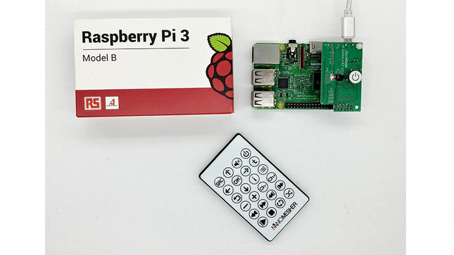
This neat little board from Nanomesher adds a programmable power switch to your Raspberry Pi A+/B+/2/3/Zero/Zero W, which can be controlled by a single button or IR remote. The Cap part of the name indicates that it connects via the GPIO pins, attached to the top of the Raspberry Pi much like a HAT. It only uses the first twelve GPIO pins, though, leaving 28 spare on (most) Raspberry Pi models allowing you to attach additional hardware. The board uses 5 V micro USB input port as the Raspberry Pi itself. You only need to press the power button on the board or on the remote and the Cap will start providing power to the RPi. Features: Fully assembled ready to use Single button or Infrared (IR) remote On / Off operation Turn off Pi by triggering system shutdown, wait for the system to be fully halted and cuts power Suitable for mounting on a front face-plate Onboard Attiny85 Microprocessor can be removed and reprogrammed if needed Open Source for both Attiny software and Shutdown Script , which means you can adopt other remote controls. Directly plug onto Raspberry Pi, no jumper cable required Infrared Remote signals of all buttons can be read from Pi. It's LIRC compatible which means you can adopt other remote controls. Kodi Control support 1 x LED controllable via GPIO 3 x I2C ports Confirmed to work with latest Pi 3 B+ as well as older Raspberry Pis Note: Raspberry Pi is not included. The Pi Switch Cap comes with the generic remote. While it works out as a Pi Switch out of the box, you can also reprogram it using an Attiny MCU programmer. Being hackable, the firmware can be modified to suit your needs. The switch can be used as an Attiny development board with the following functions: Output to trigger relay. Output to LED Analog input to detect a voltage between 0-5 V Input for push button Input fan or infrared receiver which can be coded to distinguish all the buttons in the remote included Output to trigger an external digital input (pull down) The video below features the predecessor Nanomesher Hackable Pi Switch (not Pi Switch Cap).
Eerste stappen met een ESP32-C3 en het IoTWiFi-knop en -relais IoT Cloud à la Arduino
Arduino-shield met dubbele Geiger-Müller buisuiterst gevoelige en zeer zuinige stralingssensor
CO2-wachterluchtkwaliteit bewaken – doe het zelf!
MonkMakes Air Quality Kit voor de Raspberry Pimeet temperatuur en eCO2
Alle begin......verwelkomt de diode
Tips & trucs voor het testen van componentenzonder kostbare apparatuur
Reduceer het stroomverbruik van uw mollenverjagerATtiny13 in plaats van 555
Lichtschakelaar DeLuxuiterst nauwkeurig lichtgestuurd schakelen
Uitdagingen bij het op de markt brengen van IoT-oplossingenzorgen over veiligheid, schaalbaarheid en de concurrentie Elektor Infographics
Toch beter bedraadTips voor het ontwikkelen van een 1 Gbit/s interface in de industriële omgeving
Edge Impulse FOMOreal-time objectdetectie voor MCU’s
Lopende-golfbuisVreemde onderdelen, de serie
Smalband-Internet of Thingsstandaarden, dekking, overeenkomsten en modules
Dragino LPS8 indoor-gatewayLoRaWAN-gateway snel geïnstalleerd
Ontdek ATtiny-microcontrollers met behulp van C en assemblervoorbeeldhoofdstuk: ATtiny I/O-poorten
Project 2.0correcties, updates en brieven van lezers
LoRa GPS-tracker updateontvang en toon de locatie met een Raspberry Pi
Schakelingen simuleren met TINA Design Suite & TINACloudvoorbeeldhoofdstuk: sinusoscillatoren
Uit het leven gegrepenlopendebandwerk
Het WinUI grafische framework voor Windows-appseen kleine demo-applicatie
GUI's maken met Python's Werelds slechtste GUI
Off-grid PV-systeemelektrische energie onafhankelijk van het net
De 10-jaar-smartphonestel uw verwachtingen bij Hexadoku
Your First Steps with an ESP32-C3 and the IoTA Wi-Fi Button and Relay IoT Cloud a la Arduino
Dual Geiger-Müller Tube Arduino ShieldA High Sensitivity, Very Low-Power Radiation Sensor
CO2 GuardA DIY Approach to Monitoring Air Quality
MonkMakes Air Quality Kit for Raspberry PiMeasures Temperature and eCO2
Starting Out in ElectronicsWelcome to the Diode
Tips & Tricks for Testing ComponentsNo Expensive Equipment Required
Reducing the Power Consumption of Your Mole RepellerAn ATtiny13 Replaces a 555
Light Switch DeLuxA Solution for High-Precision Light-Controlled Switching
The Challenges in Bringing IoT Solutions to MarketWorries Around Security, Scalability, and Competition Infographics 5-6/2022
Preferably Wired After AllTips for Developing a 1 Gbit/s Interface in an Industrial Environment Bringing Real-Time Object Detection to MCUs with Edge Impulse FOMO
Traveling-Wave TubesPeculiar Parts, the Series
Narrowband Internet of ThingsStandards, Coverage, Agreements, and Modules
Dragino LPS8 Indoor GatewaySpeedy LoRaWAN Gateway Setup
Explore ATtiny Microcontrollers Using C and Assembly LanguageSample Chapter: ATtiny I/O Ports
Err-lectronicsCorrections, Updates and Readers’ Letters
LoRa GPS Tracker UpdateReceive and Show Location Using a Raspberry Pi
Circuit Simulation with TINA Design Suite & TINACloudSample Chapter: Sinusoidal Oscillators
From Life’s ExperienceAssembly Line Work
The WinUI Graphics Framework for Windows AppsA Small Demo Application
GUIs with PythonWorst GUI of the world
Off-Grid Solar SystemsElectrical Energy Independent of the Mains Grid
The 10-Year SmartphoneRenew Your Expectations
HexadokuThe Original Elektorized Sudoku
Eerste stappen met een ESP32-C3 en het IoTWiFi-knop en -relais IoT Cloud à la Arduino
Arduino-shield met dubbele Geiger-Müller buisuiterst gevoelige en zeer zuinige stralingssensor
CO2-wachterluchtkwaliteit bewaken – doe het zelf!
MonkMakes Air Quality Kit voor de Raspberry Pimeet temperatuur en eCO2
Alle begin......verwelkomt de diode
Tips & trucs voor het testen van componentenzonder kostbare apparatuur
Reduceer het stroomverbruik van uw mollenverjagerATtiny13 in plaats van 555
Lichtschakelaar DeLuxuiterst nauwkeurig lichtgestuurd schakelen
Uitdagingen bij het op de markt brengen van IoT-oplossingenzorgen over veiligheid, schaalbaarheid en de concurrentie Elektor Infographics
Toch beter bedraadTips voor het ontwikkelen van een 1 Gbit/s interface in de industriële omgeving
Edge Impulse FOMOreal-time objectdetectie voor MCU’s
Lopende-golfbuisVreemde onderdelen, de serie
Smalband-Internet of Thingsstandaarden, dekking, overeenkomsten en modules
Dragino LPS8 indoor-gatewayLoRaWAN-gateway snel geïnstalleerd
Ontdek ATtiny-microcontrollers met behulp van C en assemblervoorbeeldhoofdstuk: ATtiny I/O-poorten
Project 2.0correcties, updates en brieven van lezers
LoRa GPS-tracker updateontvang en toon de locatie met een Raspberry Pi
Schakelingen simuleren met TINA Design Suite & TINACloudvoorbeeldhoofdstuk: sinusoscillatoren
Uit het leven gegrepenlopendebandwerk
Het WinUI grafische framework voor Windows-appseen kleine demo-applicatie
GUI's maken met Python's Werelds slechtste GUI
Off-grid PV-systeemelektrische energie onafhankelijk van het net
De 10-jaar-smartphonestel uw verwachtingen bij Hexadoku
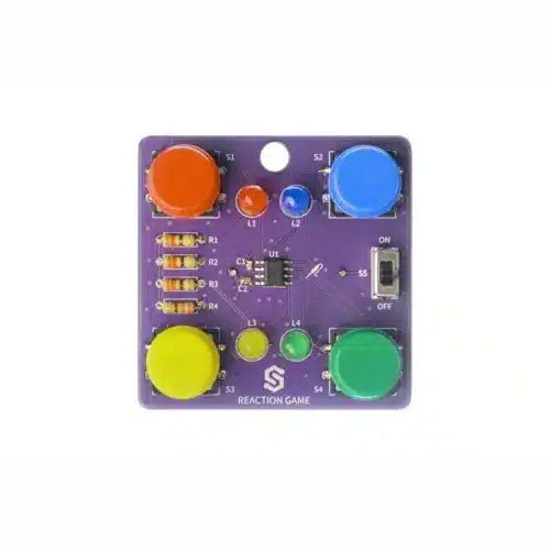
If you are looking for a simple way to learn soldering, or just want to make a small gadget that you can carry, this set is a great opportunity. Reaction game is an educational kit which teaches you how to solder, and in the end, you get to have your own small game. The goal of the game is to press the button next to the LED as soon as it turns on. With every correct answer, the game gets a bit harder – the time you have to press the button shortens. How many correct answers can you get?
It’s based on ATtiny404 microcontroller, programmed in Arduino. At its back, you’ll find CR2032 battery which makes the kit portable. There’s keychain holder as well. Soldering process is easy enough based on the mark on the PCB.
Included
1x PCB
1x ATtiny404 microcontroller
4x LEDs
4x Pushbuttons
1x Switch
4x Resistors (330 ohm)
1x CR2032 battery holder
1x Battery CR2032
1x Keychain holder
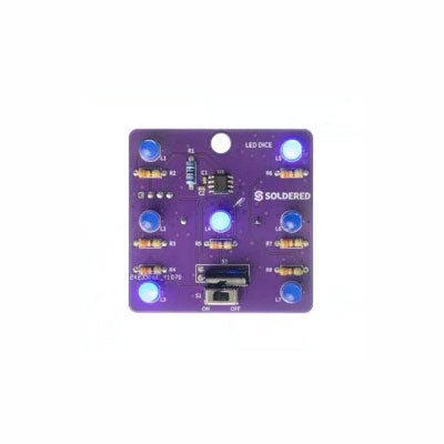
If you are looking for an easy way to get started with soldering or simply want to make a small portable gadget, this set is a great opportunity. "LED cube" is an educational set for learning the soldering skill, with which you get a small electronic game at the end. After you turn on and shake this board, certain leds will light up randomly and symbolize the number, as if a real die had been thrown.
It is based on the Attiny404 microcontroller, programmed in Arduino, and there is a battery on the back which makes this gadget portable. There is also a keychain so you can always carry your new game with you! Soldering is easy according to the markings on the board.
Included
1x PCB
1x ATtiny404 microcontroller
7x LEDs
7x Resistors (330 ohm)
1x Resistor (10 kohm)
1x Battery holder
1x CR2032 battery
1x Switch
1x Vibration sensor SW-18020P
1x Keychain ring
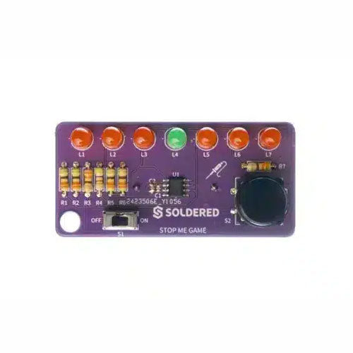
If you are looking for a simple way to learn soldering, or just want to make a small gadget that you can carry, this set is a great opportunity. Stop me game is an educational kit which teaches you how to solder, and in the end, you get to have your own small game. The LEDs go up and down, and your goal is to press the button as soon as the green LED turns on. With every correct answer, the game gets a bit harder – the time you have to press the button shortens. How many correct answers can you get?
It’s based on ATtiny404 microcontroller, programmed in Arduino. At its back, you’ll find CR2032 battery which makes the kit portable. There’s keychain holder as well. Soldering process is easy enough based on the mark on the PCB.
Included
1x PCB
1x ATtiny404 microcontroller
7x LEDs
1x Pushbutton
1x Switch
7x Resistors (330 ohm)
1x CR2032 battery holder
1x Battery CR2032
1x Keychain holder
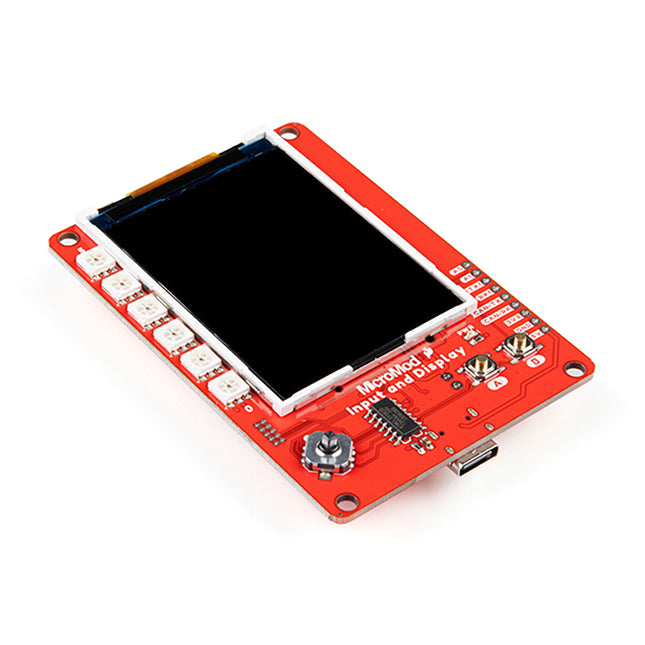
This carrier board combines a 2.4' TFT display, six addressable LEDs, onboard voltage regulator, a 6-pin IO connector, and microSD slot with the M.2 pin connector slot so that it can be used with compatible processor boards in our MicroMod ecosystem. We've also populated this carrier board with Atmel's ATtiny84 with 8kb of programmable flash. This little guy is preprogrammed to communicate with the processor over I²C to read button presses. Features M.2 MicroMod Connector 240 x 320 pixel, 2.4' TFT display 6 Addressable APA102 LEDs Magnetic Buzzer USB-C Connector 3.3 V 1 A Voltage Regulator Qwiic Connector Boot/Reset Buttons RTC Backup Battery & Charge Circuit microSD Phillips #0 M2.5 x 3 mm screw included
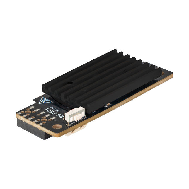
Wide Range Power Supply for Raspberry Pi
With the PiEnergy Mini, you can operate your Raspberry Pi with a voltage of 6 to 36 V DC. You can use the button integrated on the board to both power up and power down your Raspberry Pi.
Communication with the Raspberry Pi is via GPIO4, but this connection can also be cut by removing a resistor to use the pin freely. Thanks to the ultra-flat design, it can also be used in many housings. The pin header is included and not soldered on to keep the design even flatter.
Specifications
Input voltage
6 to 36 V DC
Output voltage
5.1 V
Output current
Up to 3 A (active ventilation recommended for additionally connected loads)
Cable cross-section at the power input
0.2-0.75 mm²
Interface to the Raspberry Pi
GPIO4
Microcontroller
ATtiny5
Further connections
5 V fan connector (2-pin/2.54 mm)Solder pads for external on/off switch
Compatible with
Raspberry Pi 3, 4, 5
Dimensions
23 x 56 x 11 mm
Included
Board with mounted heat sink
Pin header (2x5)
Spacer, screw, nut
Downloads
Datasheet (English)
Datasheet (Italiano)
Manual (English)
Manual (Italiano)