This bundle includes the Red Pitaya STEMlab 125-14 PRO Gen 2 Starter Kit and the new book "Experimenting with Red Pitaya STEMlab Gen 2".
The Red Pitaya STEMlab 125-14 PRO Gen 2 Starter Kit is a powerful and flexible platform for signal processing, data acquisition, and electronic measurement applications. Designed for engineers, developers, researchers, and educators, this kit provides everything required to start building advanced measurement and control systems.
At the core of the kit is the STEMlab 125-14 PRO Gen 2 board, an upgraded and ultra-lightweight development platform. Powered by the Xilinx Zynq-7010 SoC with 512 MB of RAM, it combines FPGA programmability with ARM processing power to enable high-performance instrumentation and custom signal-processing solutions.
The board offers 14-bit ADC and DAC resolution, a 125 MS/s sampling rate, an input range of ±20 V, and up to 60 MHz bandwidth. Its improved low-noise analog front-end, USB-C connectivity, and compact design make it suitable for demanding applications such as RF development, radar systems, photonics research, software-defined radio (SDR), and industrial automation.
The Starter Kit includes all essential accessories for immediate use: a microSD card with preinstalled operating system, power supply, Ethernet cable for remote access, two 100 MHz oscilloscope probes, and SMA-to-BNC adapters for flexible signal connections.
The Red Pitaya STEMlab 125-14 PRO Gen 2 Starter Kit is an excellent platform for rapid prototyping, FPGA development, measurement instrumentation, and advanced electronics experimentation.
Features
14-bit ADC and DAC resolution
125 MS/s sampling rate
±20 V input range
Up to 60 MHz bandwidth
Xilinx Zynq-7010 SoC (FPGA + ARM processor)
512 MB RAM
Low-noise analog front- and back-ends
Applications
RF development and testing
Radar and wireless systems
Software-defined radio (SDR)
Photonics and optical research
Industrial automation and control systems
Signal analysis and instrumentation
Rapid prototyping of electronic measurement systems
Specifications
Processor
Dual-core ARM Cortex-A9
FPGA
AMD Xilinx Zynq-7010 SoC
RAM
512 MB (4 Gb)
Storage
microSD card (up to 32 GB)
Operating System
Linux-based Red Pitaya OS
ADC Resolution
14-bit
DAC Resolution
14-bit
Bandwidth
60 MHz (DC)
Sampling Rate
125 MS/s
Analog Input Channels
2
Analog Output Channels
2
Input Voltage Range
±1 V (LV) / ±20 V (HV)
Input Impedance
1 MΩ / 10 pF
Output Voltage Range
±1 V
Ethernet
1x Gigabit Ethernet (RJ45)
USB
2x USB-C 2.0 (for power and console)
Digital I/O
16x GPIO (3.3 V)
Communication Interfaces
I²C, SPI, UART, CAN
Power Supply
5 V/3 A via USB-C
Dimensions
106.8 x 60.0 x 17.9 mm
Included
1x Red Pitaya STEMlab 125-14 PRO Gen 2 board
2x 100 MHz oscilloscope probes
2x SMA-to-BNC adapters
1x microSD card with preinstalled OS
1x USB-C Power supply
1x Ethernet cable
Downloads
Documentation
Schematics
Book: Experimenting with Red Pitaya STEMlab Gen 2
With this new book, Red Pitaya goes beyond a versatile board. It becomes a powerful laboratory instrument for precision measurement, analysis, and control.
From the fundamentals of electronic project development, monitoring, control, and design to testing, this book walks you step-by-step through everything you need to know to harness the full potential of Red Pitaya hardware and software.
The book presents real-time, FPGA-based projects that are developed on a PC using the Vivado environment, then transferred to the Red Pitaya for execution and testing.
You will learn about enhanced performance, expanded I/O capabilities, improved FPGA features, and advanced connectivity options that open up new frontiers for precision measurement, monitoring, and control in your embedded applications.
Inside the book you will discover:
A deep dive into Red Pitaya architecture and hardware design
Electronic experiments using Red Pitaya for measurement and monitoring
Hands-on projects using the Python programming language
Practical guidance for FPGA programming using Red Pitaya
Red Pitaya FPGA projects using the Verilog HDL under Vivado IDE
Practical design of electronic projects including measurement and testing
Step-by-step examples that bridge theory and real-world implementation
Whether you are designing your own electronic circuits, developing signal analysis tools, or creating real-time control or monitoring systems, this book provides you the knowledge and confidence you need to fully learn and customize the Red Pitaya platform.
Practical Projects and Programs
With Experimenting with Red Pitaya STEMlab Gen 2, Red Pitaya goes beyond a versatile board. It becomes a powerful laboratory instrument for precision measurement, analysis, and control.
From the fundamentals of electronic project development, monitoring, control, and design to testing, this book walks you step-by-step through everything you need to know to harness the full potential of Red Pitaya hardware and software.
The book presents real-time, FPGA-based projects that are developed on a PC using the Vivado environment, then transferred to the Red Pitaya for execution and testing.
You will learn about enhanced performance, expanded I/O capabilities, improved FPGA features, and advanced connectivity options that open up new frontiers for precision measurement, monitoring, and control in your embedded applications.
Inside the book you will discover:
A deep dive into Red Pitaya architecture and hardware design
Electronic experiments using Red Pitaya for measurement and monitoring
Hands-on projects using the Python programming language
Practical guidance for FPGA programming using Red Pitaya
Red Pitaya FPGA projects using the Verilog HDL under Vivado IDE
Practical design of electronic projects including measurement and testing
Step-by-step examples that bridge theory and real-world implementation
Whether you are designing your own electronic circuits, developing signal analysis tools, or creating real-time control or monitoring systems, this book provides you the knowledge and confidence you need to fully learn and customize the Red Pitaya platform.
Practical Projects and Programs
With Experimenting with Red Pitaya STEMlab Gen 2, Red Pitaya goes beyond a versatile board. It becomes a powerful laboratory instrument for precision measurement, analysis, and control.
From the fundamentals of electronic project development, monitoring, control, and design to testing, this book walks you step-by-step through everything you need to know to harness the full potential of Red Pitaya hardware and software.
The book presents real-time, FPGA-based projects that are developed on a PC using the Vivado environment, then transferred to the Red Pitaya for execution and testing.
You will learn about enhanced performance, expanded I/O capabilities, improved FPGA features, and advanced connectivity options that open up new frontiers for precision measurement, monitoring, and control in your embedded applications.
Inside the book you will discover:
A deep dive into Red Pitaya architecture and hardware design
Electronic experiments using Red Pitaya for measurement and monitoring
Hands-on projects using the Python programming language
Practical guidance for FPGA programming using Red Pitaya
Red Pitaya FPGA projects using the Verilog HDL under Vivado IDE
Practical design of electronic projects including measurement and testing
Step-by-step examples that bridge theory and real-world implementation
Whether you are designing your own electronic circuits, developing signal analysis tools, or creating real-time control or monitoring systems, this book provides you the knowledge and confidence you need to fully learn and customize the Red Pitaya platform.
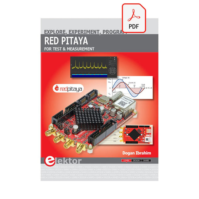
The Red Pitaya (STEMlab) is a credit card-sized, open-source test and measurement board that can be used to replace most measurement instruments used in electronics laboratories. With a single click, the board can transform into a web-based oscilloscope, spectrum analyser, signal generator, LCR meter, Bode plotter, and microcontroller.
The Red Pitaya (STEMlab) can replace the many pieces of expensive measurement equipment found at professional research organisations and teaching laboratories. The device, that based on Linux, includes an FPGA, digital signal processing (DSP), dual core ARM Cortex processor, signal acquisition and generation circuitry, micro USB socket, microSD card slot, RJ45 socket for Ethernet connection, and USB socket – all powered from an external mains adaptor.
This book is an introduction to electronics. It aims to teach the principles and applications of basic electronics by carrying out real experiments using the Red Pitaya (STEMlab). The book includes many chapters on basic electronics and teaches the theory and use of electronic components including resistors, capacitors, inductors, diodes, transistors, and operational amplifiers in electronic circuits. Many fun and interesting Red Pitaya (STEMlab) experiments are included in the book. The book also makes an introduction to visual programming environment.
The book is written for college level and first year university students studying electrical or electronic engineering.
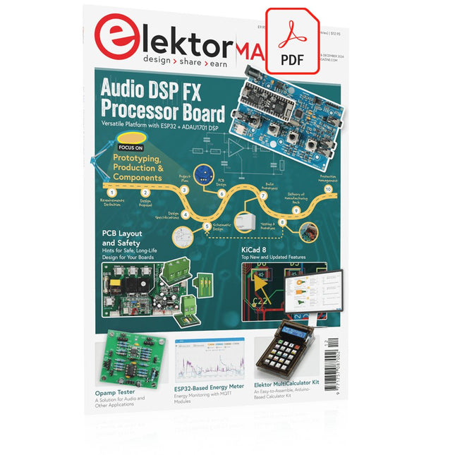
Elektor GREEN and GOLD members can download their digital edition here.
Not a member yet? Click here.
Audio DSP FX Processor BoardPart 1: Features and Design
50 Years of Elektor in English
KiCad 8Top New and Updated Features
Elektor MultiCalculator KitAn Arduino-Based Calculator Kit for Electronic Purposes
Low-Cost GNSS RTK SystemsWith Centimeter-Level Degree of Accuracy
PCB Layout and SafetyHints for a Safe, Long-Life Design of Your Boards
Opamp TesterFor Audio and Other Applications
Project Update #4: ESP32-Based Energy MeterEnergy Monitoring with MQTT
Real-Time Spectrum Analyzer with Waveguide Technology and Multi-Interface PCsAaronia Establishes New Product Segment and Presents First Prototypes at Electronica in Munich
Applications of Ynvisible’s E-paper DisplaysTransform Businesses and Shape the Future
SMT InductorsCoils and Ferrites — Selection Made Easy
Arrow Electronics to Showcase Innovative Technologies at electronica 2024
Using EMI Shielding to Achieve Electromagnetic Compatibility Compliance
The Ultimate Tool for Every Electronics EnthusiastUnlock Endless Possibilities with Red Pitaya and 1,000+ Click Boards™
V-LD1 Distance Radar Module
Siglent Presents Its New Vector Network Analyzer Platform SNA6000A
HDI in the MiddleA New Cost-Effective PCB Pooling Service for Tiny BGAs
Remote Access IoT LabOne and Only Solution for Remote Learning and Development in Embedded Industry
Challenges of DFM Analysis for Flex and Rigid-Flex Design
From Life's ExperienceMicrotechnophobia
3D Christmas TreeA 3D PCB with a Low-Cost, 32-bit Microcontroller
Starting Out in Electronics……Continues with the Opamp!
An Autonomous Sensor Node (Project Update #1)Reducing Idle Power Consumption with External RTC and Power Switch
2024: An AI OdysseyA Look Back at the Future
LED Displays with the MAX7219A Hands-On Approach to a Great Chip
Err-lectronicsCorrections, Updates, and Readers’ Letters
VibroTactile GlovesA Breakthrough for Parkinson’s Patients
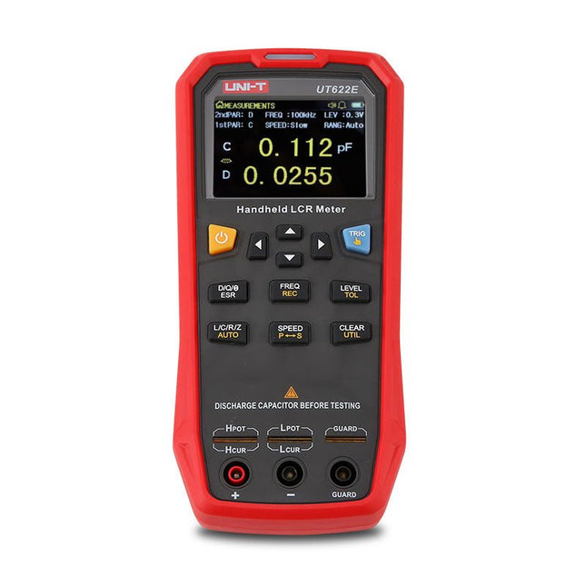
The UT622E handheld LCR meter features powerful functions, high accuracy, fast speed, and long standby time. With a clear and intuitive 2.8-inch TFT LCD display, large-capacity rechargeable battery, and 100 kHz test frequency, the meter can be used for longstanding accurate and convenient measurement in any occasion.
It is suitable for the measurement and screening of inductance, capacitance, and resistance in laboratories, production lines, maintenance points, etc.
Features
Max. test frequency: 100 kHz
Accuracy: 0.1%
Display count: 99999
Max. test rate: 20 times/s
DCR: Yes
Connectivity: Mini-USB
Display: 2.8" TFT LCD
Specifications
Testfrequency
100 Hz, 120 Hz, 1 kHz, 10 kHz, 100 kHz
Test level
0.1 Vmrs, 0.3 Vrms, 1 Vrms
Output impedance
100 Ω
Measurement parameters
Primary: L/C/R/Z/DCRSecondary: D/Q/Θ/ESR
DSR speed test
Fast (20 times/s), medium (5 times/s), or slow (2 times/s)
Range
Auto/Hold
Tolerance range
1%~20%
Equivalent mode
Series/Parallel
Clearing connection
Open/Short circuit
Fuse of test ports
0.1 A/250 V
Communication interface
Mini-USB
MAX reading of primary parameters
99999
MIN resolution
0.0001
Maximum accuracy
0.10%
L
0.00 µH~99.999 H
C
0.00 pF~99.999 mF
Z/R
0.0000 Ω~9.9999 MΩ
ESR
0.0000 Ω~999.99 Ω
D
0.0000~9.9999
Q
0.0000~99999
Θ
-179.9°~179.9°
DCR
0.01 mΩ~20.000 MΩ
Power supply
3.7 V/1800 mAh lithium polymer battery
Display
2.8" TFT LCD (320x240)
Dimensions
93 x 192 x 44 mm
Weight
420 g
Included
UT622E LCR meter
Short circuit board
Four-terminal kelvin test leads
USB cable
Manual
Downloads
Datasheet
Manual
Software
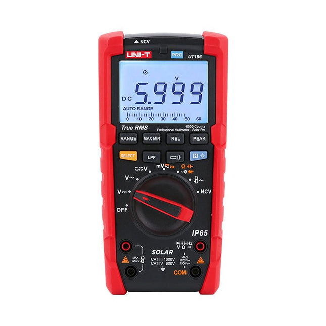
The UT196 True RMS solar multimeter is an ideal tool for solar power system maintenance. This rugged meter is designed for technicians who work in rugged outdoor environments. UT196 can measure up to 1700 V DC and 1500 V AC voltages, and 3000 A AC current with an external current clamp sensor. This solar meter offers IP65 protection and able to withstand 2 m drop as well.
The UT196 solar multimeter is designed with 1700 V DC, 1500 Vrms AC overload protection and tested for safe usage in CAT III 1000 V, CAT IV 600 V environments.
Features
True RMS
Measure up to 1700 V DC and 1500 V AC for high voltage applications e.g. solar array, wind
IP65 protection
CAT III 1000V, CAT IV 600 V
Analog bar
Frequency response: 45 Hz~1 kHz
Low-pass filter function
Low impedance mode
Built-in flashlight, bright backlight and visual alarm
Applications
High DC voltage measurement
Output voltage and frequency measurement
Voltage and frequency measurement
Current and frequency measurement
Specifications
Range
UT196
DC voltage (V)
1700 V
±0.2% +5
AC voltage (V)
1500 V
±0.8% +3
Frequency (Hz)
1 MHz
±0.08% +4
Resistance (Ω)
60 MΩ
±0.8% +2
Capacitance (F)
60 mF
±1.9% +5
Power
9 V battery
Dimensions
195 x 95 x 58 mm
Included
UT196 Solar Multimeter
Battery
Test leads
Downloads
Datasheet
Manual
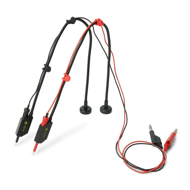
The SQ series of handsfree PCBite probes from Sensepeek are insulated, come with included color-coded cable holders and have a lower point of gravity making them even more stable compared with the original SP series of probes. All the loved features of handsfree measurement, exchangeable fine pitch spring tipped test needle and the minimalistic design is maintained to make traditional sized and handheld probes obsolete.
Features
All handsfree probes from Sensepeek makes instant measurements or long triggering sessions a breeze.
No more soldering wires to connect your probe or complicated tools to setup, just positioning the probe needle on any test point or component in the signal path and release.
Saves time and frustration during development, verification and repairs. The minimalist design and the spring-loaded test needle makes it possible to simultaneously measure on fine pitch components and nearby signals.
Both length and weight of the SQ probes are perfectly balanced to be used with PCBite PCB holders and base plate which is a must for handsfree function.
The probe holder comes with a powerful magnet in the base, as for all PCBite probes and holders which makes the probe easy to place and reposition.
The SQ series of probes can be used handheld without the probe holder as they have an insulated grip but their full potential is used when measuring handsfree.
Included
2x SQ10 probes and pin tipped test needles (red/black)
2x Banana to dupont test wires (red/black)
1x Set of cable holders (red/black)
2x Extra test needles
Downloads
User guide
The Raspberry Pi SSD unlocks outstanding performance for I/O intensive applications on Raspberry Pi 5 and other devices, including super-fast startup when booting from SSD.
It is a reliable, responsive, and high-performance PCIe Gen 3-compliant SSD capable of fast data transfer, available also with 512 GB capacity.
Features
40k IOPS (4 kB random reads)
70k IOPS (4 kB random writes)
Downloads
Datasheet
The Raspberry Pi SSD unlocks outstanding performance for I/O intensive applications on Raspberry Pi 5 and other devices, including super-fast startup when booting from SSD.
It is a reliable, responsive, and high-performance PCIe Gen 3-compliant SSD capable of fast data transfer, available also with 256 GB capacity.
Features
50k IOPS (4 kB random reads)
90k IOPS (4 kB random writes)
Downloads
Datasheet