Search results for "grundschaltungen OR der OR elektronik"
-
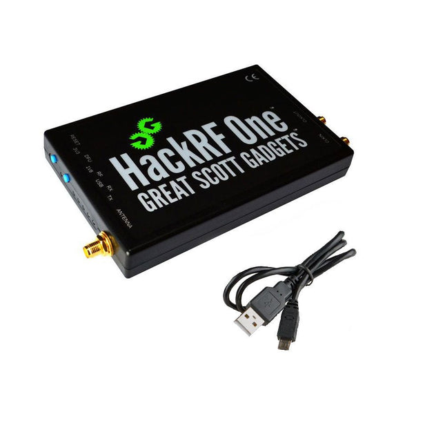
Great Scott Gadgets Great Scott Gadgets HackRF One SDR (1 MHz – 6 GHz)
New Version available! Click here! HackRF One is a Software Defined Radio (SDR) peripheral capable of transmission or reception of radio signals from 1 MHz to 6 GHz. Designed to enable test and development of modern and next generation radio technologies, HackRF One is an open source hardware platform that can be used as a USB peripheral or programmed for stand-alone operation. Specifications 1 MHz to 6 GHz operating frequency Half-duplex transceiver Up to 20 million samples per second 8-bit quadrature samples (8-bit I and 8-bit Q) Compatible with GNU Radio, SDR and more Software-configurable RX and TX gain and baseband filter Software-controlled antenna port power (50 mA at 3.3 V) SMA female antenna connector SMA female clock input and output for synchronization Convenient buttons for programming Internal pin headers for expansion Hi-Speed USB 2.0 USB-powered Open source hardware HackRF One is test equipment for RF systems. It has not been tested for compliance with regulations governing transmission of radio signals. You are responsible for using your HackRF One legally. Included 1x HackRF One SDR 1x Plastic enclosure 1x micro-USB cable Note: An antenna is not included. ANT500 is recommended as a starter antenna for HackRF One. Downloads Documentation GitHub Source code and hardware design files
-
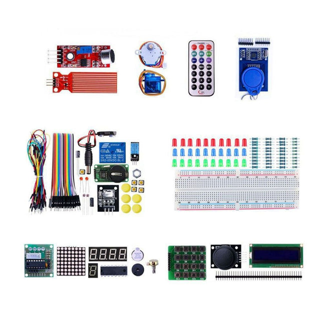
Makerfabs Arduino Uno Experimenting Kit
With this kit you can built all the projects described in the book 'Mastering the Arduino Uno R4'. The kit comes with several LEDs, sensors, actuators, and other components. The purpose of the kit is to make a flying start with hardware and software aspects of projects designed around the Arduino Uno microcontroller system. Included 1x RFID reader module 1x DS1302 clock module 1x 5 V stepper motor 1x '2003' stepper motor drive board 5x Green LED 5x Yellow LED 5x Red LED 2x Rocker switch 1x Flame sensor 1x LM35 sensor module 1x Infrared receiver 3x Light-dependent resistors (LDRs) 1x IR remote controller 1x Breadboard 4x Pushbutton (with four caps) 1x Buzzer 1x Piezo sounder 1x Adjustable resistor (potentiometer) 1x 74HC595 shift register 1x 7-segment display 1x 4-digit 7-segment display 1x 8x8 Dot-matrix display 1x 1602 / I²C LCD module 1x DHT11 Temperature and humidity module 1x Relay module 1x Sound module Set of Dupont cables Set of Breadboard cables 1x Water sensor 1x PS2 Joystick 5x 1 k-ohm resistor 5x 10 k-ohm resistor 5x 220-ohm resistor 1x 4x4 keypad module 1x 9g Servo (25 cm) 1x RFID card 1x RGB module 1x 9 V battery DC jack Not included Mastering the Arduino Uno R4 (Book) Arduino Uno R3/R4 (Board)
-
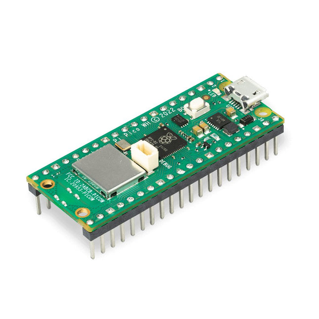
Raspberry Pi Foundation Raspberry Pi Pico WH
Raspberry Pi Pico WH is a microcontroller board based on the Raspberry Pi RP2040 microcontroller chip. The RP2040 microcontroller chip ('Raspberry Silicon') offers a dual-core ARM Cortex-M0+ processor (133 MHz), 256 KB RAM, 30 GPIO pins, and many other interface options. In addition, there is 2 MB of on-board QSPI flash memory for code and data storage. Raspberry Pi Pico WH has been designed to be a low cost yet flexible development platform for RP2040 with a 2.4 GHz wireless interface using an Infineon CYW43439. The wireless interface is connected via SPI to the RP2040. Features of Pico WH RP2040 microcontroller with 2 MB of flash memory On-board single-band 2.4 GHz wireless interfaces (802.11n) Micro USB B port for power and data (and for reprogramming the flash) 40 pin 21 x 51 mm 'DIP' style 1 mm thick PCB with 0.1' through-hole pins also with edge castellations Exposes 26 multi-function 3.3 V general purpose I/O (GPIO) 23 GPIO are digital-only, with three also being ADC capable Can be surface mounted as a module 3-pin ARM serial wire debug (SWD) port Simple yet highly flexible power supply architecture Various options for easily powering the unit from micro USB, external supplies or batteries High quality, low cost, high availability Comprehensive SDK, software examples and documentation Pre-populated headers and 3-pin debug connector Features of the RP2040 microcontroller Dual-core cortex M0+ at up to 133 MHz On-chip PLL allows variable core frequency 264 kByte multi-bank high performance SRAM External Quad-SPI Flash with eXecute In Place (XIP) and 16 kByte on-chip cache High performance full-crossbar bus fabric On-board USB1.1 (device or host) 30 multi-function general purpose I/O (four can be used for ADC) 1.8-3.3 V I/O voltage 12-bit 500 ksps analogue to digital converter (ADC) Various digital peripherals 2x UART, 2x I²C, 2x SPI, 16x PWM channels 1x timer with 4 alarms, 1x real time clock 2x programmable I/O (PIO) blocks, 8 state machines in total Flexible, user-programmable high-speed I/O Can emulate interfaces such as SD card and VGA Note: Raspberry Pi Pico W I/O voltage is fixed at 3.3 V. Downloads Datasheet Specifications of 3-pin Debug Connector
-

LabNation LabNation SmartScope USB Oscilloscope
SmartScope is a compact 2-channel USB oscilloscope with a bandwidth of 30 MHz and a sampling rate of 2x 100 MSa/s. It is compatible with all major platforms, including Windows, macOS, Linux, and Android. The operation and display of measurement signals are done via smartphone, tablet, or PC. Additionally, a logic analyzer and a signal generator are integrated. Even more, you can get mobile with it: take the SmartScope on the road, thanks to the single-cable connectivity. Everything is going to be intuitive: pointing, pinching and swiping finally replaces the clunky interfaces of old scopes. With the SmartScope you develop your digital interfaces using the 100 MS/s logic analyzer. With this tool you can design any signal you want using Excel, then upload it to the built-in Arbitrary Waveform Generator (AWG). At the end capture the voltage at any point of your design at 100 million times each second. The Software for the support of Windows / macOS / Linux / Android and Export formats (Excel .csv / Matlab .mat) are given. Features Channel sampled at 100 MHz/s each AC/DC coupling on analog inputs 100% silent 64 Mbit RAM: x10000 zoom Arbitrary Waveform Generator 8 digital inputs at 100 MS/s each 4 digital outputs at 100 MS/s each Externally power your scope in case your mobile can't supply the juice. Specifications Oscilloscope Bandwidth 30 MHz (-3 dB point) Sample rate 2x 100 MS/s Channels 2 Max pre-trigger position 16x full scale Max post-trigger position Full scale Max full voltage scale 10 V/div (±35 V input range) Min full voltage scale 20 mV/div Analog input range -35 V, +35 V Max input peak-to-peak 40 V Signal coupling AC / DC Precision 8 bit Input impedance 1 MΩ // 10 pF Waverforms 200 waveforms/s Data delay to host < 10 ms Sample depth Up to 4 million samples per channel External trigger Yes Logic Analyzer Input channels 8 Input impedance 100 kOhm // 2 pF to GND Sample rate 100 MS/s Logic level 1.8 V to 5.0 V Diode protection Bidirectional Input data buffer 4 million samples Waverforms 200 waveforms/s Data delay to host < 10 ms Protocol decoders I²C, SPI, UART, I²S integrated User extensible Wave Generator (Analog Output) Output channels 1 Data rate Up to 50 MS/s Output level 0-3.3 V (Opamp driven) Output buffer Up to 2048 samples Max slew rate 30 ns/V Step 13 mV Wave Generator (Digital Output) Channels 4 Data rate Up to 100 MS/s Output level 3.3 V or 5 V (selectable) Output buffer Up to 2048 samples Diode protected Yes Programmable Logic USB controller MicroChip PIC18F14K50 USB interface PicKit3 or USB flashable FPGA Xilinx Spartan 6 FPGA interface JTAG and USB flashable Size & Weight Dimensions (L x W x D) 110 x 64 x 24.2 mm (4.33 x 2.52 x 0.95") Weight 158 g Case Aluminium Connectivity Device/Host mini USB included Record waveforms Store Matlab (.mat) or Excel (.csv) files through Dropbox Analog BNC 2 probes included Digital 8x 0.1" pitch, probes (included) Sync USB micro B-B Power USB micro B (optional) Included 1x SmartScope USB Oscilloscope 2x Analog probes 1x Digital probe cable 1x USB cable Downloads Software GitHub Wiki
-

Raspberry Pi Foundation Raspberry Pi Compute Module 5 Development Kit
The Raspberry Pi Compute Module 5 Development Kit provides an ideal platform for prototyping embedded solutions. This all-in-one kit contains the Compute Module 5, the Compute Module 5 IO Board and all necessary accessories to start your product design. Compute Module 5 (CM5104032) 2.4 GHz quad-core 64-bit Arm Cortex-A76 CPU VideoCore VII GPU, supporting OpenGL ES 3.1 and Vulkan 1.3 4 GB LPDDR4X-4267 SDRAM 32 GB MLC eMMC memory 1x Dual 4Kp60 HDMI display output 1x 4Kp60 HEVC decoder 1x Dual-band 802.11ac Wi-Fi and Bluetooth 5.0 2x USB 3.0 interfaces, supporting simultaneous 5 Gbps operation 1x Gigabit Ethernet, with IEEE 1588 support 2x 4-lane MIPI camera/display transceivers 1x PCIe 2.0 interface for fast peripherals 30 GPIOs, supporting 1.8 V or 3.3 V operation Peripherals: UART, SPI, I²C, I²S, SDIO, and PWM Compute Module 5 IO Board 1x Standard 40-pin GPIO 2x Full-size HDMI 2.0 2x 4-lane MIPI DSI/CSI-2 FPC (22-pin, 0.5 mm pitch cable) 2x USB 3.0 1x Gigabit Ethernet jack with PoE+ support (requires a separate Raspberry Pi PoE+ HAT+) 1x M.2 M-key PCIe socket (for 2230, 2242, 2260 and 2280 modules) 1x microSD card socket (for use with Lite modules) 1x RTC battery socket 1x 4-pin fan connector Compute Module 5 IO Case The metal case transforms the IO Board into a fully enclosed, industrial-grade computer. Designed specifically for the Raspberry Pi Compute Module 5, the IO Case features a built-in fan that connects to the IO Board's 4-pin fan connector, ensuring enhanced thermal performance. Included 1x Raspberry Pi Compute Module 5 (Wireless, 4 GB RAM, 32 GB eMMC) 1x Raspberry Pi Compute Module 5 IO Board (supplied pre-fitted inside the IO Case) 1x Raspberry Pi Compute Module 5 IO Case 1x Raspberry Pi Compute Module 5 Cooler 1x Raspberry Pi Antenna Kit 1x Raspberry Pi 27 W USB-C PD Power Supply (EU) 2x Raspberry Pi HDMI to HDMI cables 1x Raspberry Pi USB-A to USB-C cable Downloads Datasheet (Compute Module 5) Datasheet (IO Board) Datasheet (IO Case) Datasheet (Cooler) Datasheet (Antenna Kit)


