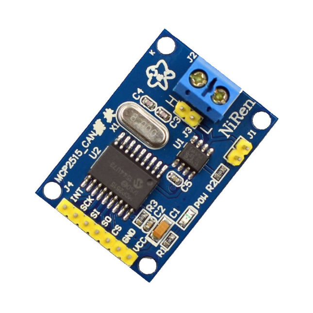
This CAN Module is based on the CAN bus controller MCP2515 and CAN transceiver TJA1050. With this module, you will easy to control any CAN Bus device by SPI interface with your MCU, such as Arduino Uno and so on. Features Support CAN V2.0B Communication rate up to 1 MB/s Working Voltage: 5 V Working Current: 5 mA Interface: SPI Downloads MCP2515 Datasheet TJA1050 Datasheet
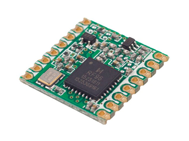
The RFM95 is a LoRa / SigFox module to be used with Arduino / ESP32 / Raspberry Pi and many other. With ideal conditions, you can get ranges up to 2km+ while having only small power consumption. It is equipped with the LoRa long range modem that provides ultra-long range spread spectrum communication and high interference immunity. Using the patented LoRa™ modulation technique RFM95 can achieve a sensitivity of over -148dBm using a low-cost crystal and bill of materials. The high sensitivity combined with the integrated +20 dBm power amplifier yields industry leading link budget making it optimal for any application requiring range or robustness. Features maximum link budget: 168 dB +20 dBm - 100 mW constant RF output vs. V supply +14 dBm high efficiency PA Programmable bit rate up to 300 kbps. High sensitivity: down to -148 dBm. Bullet-proof front end: IIP3 = -12.5 dBm. Built-in bit synchronizer for clock recovery. Excellent blocking immunity. Low RX current of 10.3 mA, 200 mA register retention. Fully integrated synthesizer with a resolution of 61 Hz. FSK, GFSK, MSK, GMSK, LoRa™ and OOK modulation. Preamble detection. 127 dB Dynamic Range RSSI. Automatic RF Sense and CAD with ultra-fast AFC. Packet engine up to 256 bytes with CRC. Built-in temperature sensor Low battery indicator. Dimensions: 16 x 16 mm Applications Automated Meter Reading Home and Building Automation Wireless Alarm and Security Systems Industrial Monitoring and Control Long range Irrigation Systems
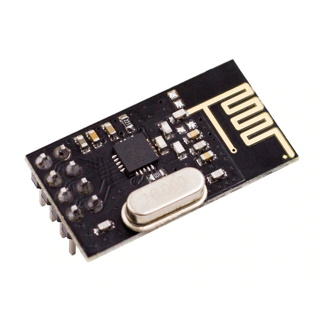
NRF24L01 is a universal ISM band monolithic transceiver chip works in the 2.4-2.5 GHz. Features Wireless transceiver including: Frequency generator, enhanced type, SchockBurstTM, mode controller, power amplifier, crystal amplifier, modulator, demodulator The output power channel selection and protocol settings can be set extremely low current consumption, through the SPI interface As the transmit mode, the transmit power is 6 dBm, the current is 9.0 mA, the accepted mode current is 12.3 mA, the current consumption of the power-down mode and standby mode are lower Built-in 2.4 GHz antenna, supports up to six channels of data reception Size: 15 x 29 mm (including antenna)
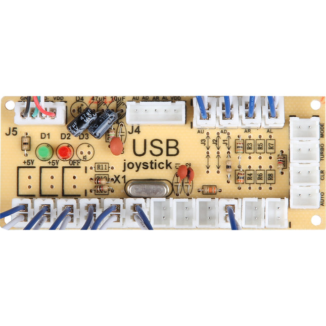
The Zero Delay Encoder Encoder makes it simple to attach your own arcade joysticks and buttons, and to connect to the Raspberry, PC or other devices. Create your own controller and enjoy your games without any compromises or control your robot project according to your ideas. Features Compatible with Linux, Windows, MAME and other common emulators and systems. Complete controller base with all cables included Supports up to 12 buttons Auto, Fire and Turbo modes Additional connection: Sanwa/Seimitsu 5-Pin LEDs: 1 × Power-LED, 1 × Mode-LED The scope of delivery includes Zero Delay Encoder, USB Cable, 13 × 4.8 mm cable.
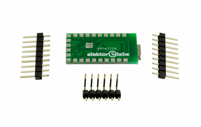
In 2011 we published a small PCB, FT232R USB/Serial Bridge/BOB (110553) with a USB-UART IC from FTDI, the FT232RQ. Here we present its successor with a cheaper version, an FT231XQ. But there are some other changes too. Instead of connectors, alongside the PCB, normal pin headers are used that are mounted on the bottom side and make the PCB a little smaller when mounted, compared to the old BoB. An ESD protection device (D1) is added in the USB data signal lines for extra safety. Despite less room for all parts to fit on the PCB, it is only a little over 2 mm longer. The FT231 has four configurable CBUS I/O pins, one less now. More importantly, however, the power supply for the I/O's VCCIO is only specified for +1.8 V to +3.3 but is 5 V tolerant for external UART logic running on +5 V. The +3.3 V internal regulator of the FT231 can deliver 50 mA to external circuitry. The manufacturer FTDI has a utility to configure several settings, FTPROG. Such as the function of the CBUS pins. By default, CBUS1 and CBUS 2 are low-level outputs to drive receive and transmit LEDs, indicating data transfer on the USB bus. So, when receiving data through the UART, the TX LED lights up. If you prefer this the other way around, FTPROG can be used to change this. But be careful the chip can become unresponsive when wrong settings are programmed. Some of the more important properties of the new BoB: Micro-USB connector USB 2.0 Full Speed capable VCCIO +1.8...+3.3 V (max. 4 V, 5 V input from UART logic tolerant) +3.3 V regulator output, max. 50 mA Data transfer 300 baud to 3 Mbaud UART Compatible with RS232, RS485, and RS422 I/O pin output drive 4 mA - 16 mA 4 configurable CBUS pins Here you can find information regarding the EEPROM Programming Utility, the VCP Drivers and the D2XX Drivers.
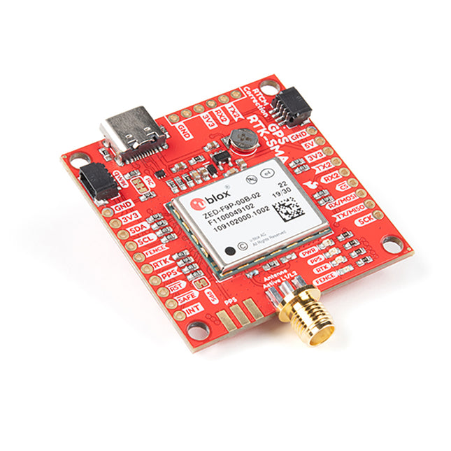
Based on the SparkFun GPS-RTK2 designs, the SparkFun GPS-RTK-SMA raises the bar for high-precision GPS and is the latest in a line of powerful RTK boards featuring the ZED-F9P module from u-blox. The ZED-F9P is a top-of-the-line module for high accuracy GNSS and GPS location solutions, including RTK capable of 10mm, three-dimensional accuracy. With this board, you will be able to know where your (or any object's) X, Y, and Z location is within roughly the width of your fingernail! The ZED-F9P is unique in that it is capable of both rover and base station operations. Utilizing our handy Qwiic system, no soldering is required to connect it to the rest of your system. However, we still have broken out 0.1'-spaced pins if you prefer to use a breadboard. We've included a rechargeable backup battery to keep the latest module configuration and satellite data available for up to two weeks. This battery helps 'warm start' the module decreasing the time-to-first-fix dramatically. This module features a survey-in mode allowing the module to become a base station and produce RTCM 3.x correction data. Based on your feedback, we switched out the u.FL connector and included an SMA connector in this version of the board. The number of configuration options of the ZED-F9P is incredible! Geofencing, variable I²C address, variable update rates, even the high precision RTK solution can be increased to 20Hz. The GPS-RTK2 even has five communications ports which are all active simultaneously: USB-C (which enumerates as a COM port), UART1 (with 3.3V TTL), UART2 for RTCM reception (with 3.3V TTL), I²C (via the two Qwiic connectors or broken out pins), and SPI. SparkFun has also written an extensive Arduino library for u-blox modules to easily read and control the GPS-RTK-SMA over our Qwiic Connect System. Leave NMEA behind! Start using a much lighter weight binary interface and give your microcontroller (and its one serial port) a break. The SparkFun Arduino library shows how to read latitude, longitude, even heading and speed over I²C without the need for constant serial polling. Features Concurrent reception of GPS, GLONASS, Galileo and BeiDou Receives both L1C/A and L2C bands Voltage: 5 V or 3.3 V, but all logic is 3.3 V Current: 68 mA - 130 mA (varies with constellations and tracking state) Time to First Fix: 25 s (cold), 2 s (hot) Max Navigation Rate: PVT (basic location over UBX binary protocol) - 25 Hz RTK - 20 Hz Raw - 25 Hz Horizontal Position Accuracy: 2.5 m without RTK 0.010 m with RTK Max Altitude: 50 km Max Velocity: 500 m/s Weight: 6.8 g Dimensions: 43.5 mm x 43.2 mm 2 x Qwiic Connectors
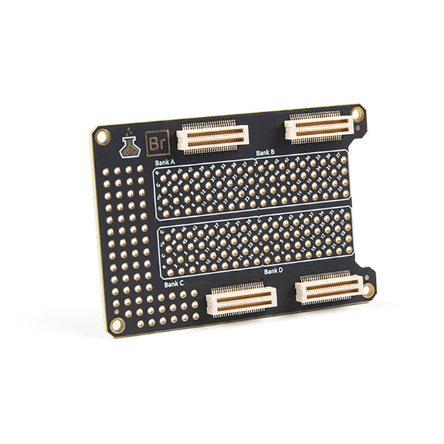
Alchitry Elements are expansion boards similar to shields for an Arduino or HATs for a Raspberry Pi, but these are meant for your Au and Cu FPGA Development Boards. This Element is equipped with four connectors on top and four on the bottom for maximum stackability that snaps to an Au or Cu board.
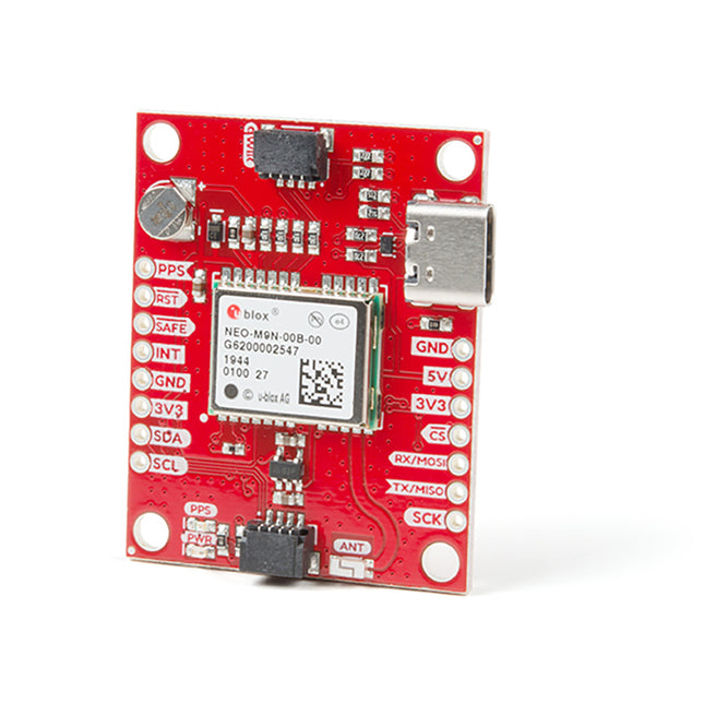
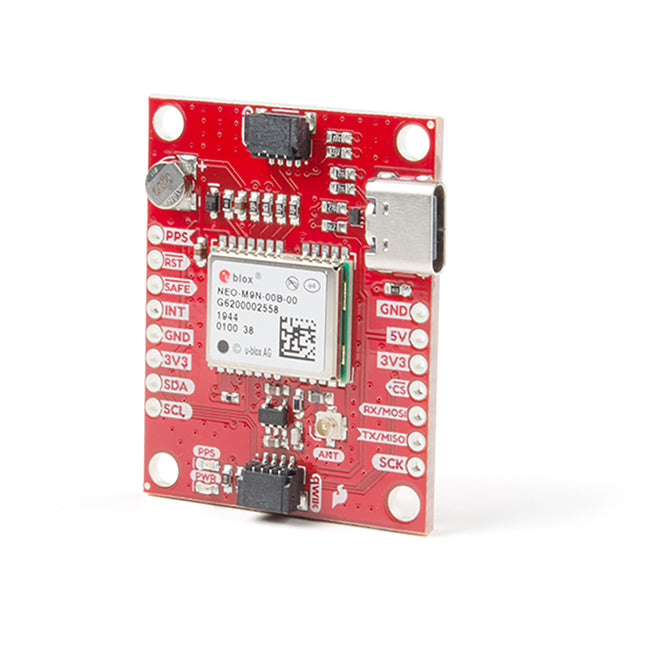
Thanks to the onboard rechargeable battery, you'll have backup power enabling the GPS to get a hot lock within seconds! Additionally, this u-blox receiver supports I²C (u-blox calls this Display Data Channel), making it perfect for the Qwiic compatibility, so we don't have to use up our precious UART ports. Utilizing our handy Qwiic system, no soldering is required to connect it to the rest of your system. However, we still have broken out 0.1'-spaced pins if you prefer to use a breadboard. The NEO-M9N module detects jamming and spoofing events and can reports them to the host so that the system can react to such events. A SAW (Surface Acoustic Wave) filter combined with an LNA (Low Noise Amplifier) in the RF path is integrated into the NEO-M9N module, allowing normal operation even under strong RF interferences. U-blox based GPS products are configurable using the popular but dense, windows program called u-centre. Plenty of different functions can be configured on the NEO-M9N: baud rates, update rates, geofencing, spoofing detection, external interrupts, SBAS/D-GPS, etc. All of this can be done within the SparkFun Arduino Library! The SparkFun NEO-M9N GPS Breakout is also equipped with an on-board rechargeable battery that provides power to the RTC on the NEO-M9N. This reduces the time-to-first fix from a cold start (~24s) to a hot start (~2s). The battery will maintain RTC and GNSS orbit data without being connected to power for plenty of time. Features Integrated Chip Antenna 92-Channel GNSS Receiver 1.5m Horizontal Accuracy 25Hz Max Update Rate (4 concurrent GNSS) Time-To-First-Fix: Cold: 24 s Hot: 2 s Max Altitude: 80,000 m Max G: ≤4 Max Velocity: 500 m/s Velocity Accuracy: 0.05 m/s Heading Accuracy: 0.3 degrees Time Pulse Accuracy: 30 ns 3.3 V VCC and I/O Current Consumption: ~31 mA Tracking GPS+GLONASS Software Configurable Geofencing Odometer Spoofing Detection External Interrupt Pin Control Low Power Mode Many others! Supports NMEA, UBX, and RTCM protocols over UART or I²C interfaces
Additionally, this u-blox receiver supports I²C (u-blox calls this Display Data Channel), making it perfect for the Qwiic compatibility, so we don't have to use up our precious UART ports. Utilizing our handy Qwiic system, no soldering is required to connect it to the rest of your system. However, we still have broken out 0.1'-spaced pins if you prefer to use a breadboard. The NEO-M9N module detects jamming and spoofing events and can reports them to the host so that the system can react to such events. A SAW (Surface Acoustic Wave) filter combined with an LNA (Low Noise Amplifier) in the RF path is integrated into the NEO-M9N module, allowing normal operation even under strong RF interferences. U-blox based GPS products are configurable using the popular but dense, windows program called u-centre. Plenty of different functions can be configured on the NEO-M9N: baud rates, update rates, geofencing, spoofing detection, external interrupts, SBAS/D-GPS, etc. All of this can be done within the SparkFun Arduino Library! The SparkFun NEO-M9N GPS Breakout is also equipped with an on-board rechargeable battery that provides power to the RTC on the NEO-M9N. This reduces the time-to-first fix from a cold start (~24s) to a hot start (~2s). The battery will maintain RTC and GNSS orbit data without being connected to power for plenty of time. Features Integrated U.FL connector for use with an antenna of your choice 92-Channel GNSS Receiver 1.5 m Horizontal Accuracy 25 Hz Max Update Rate (4 concurrent GNSS) Time-To-First-Fix: Cold: 24 s Hot: 2 s Max Altitude: 80,000 m Max G: ≤ 4 Max Velocity: 500 m/s Velocity Accuracy: 0.05 m/s Heading Accuracy: 0.3 degrees Time Pulse Accuracy: 30 ns 3.3 V VCC and I/O Current Consumption: ~31 mA Tracking GPS+GLONASS Software Configurable Geofencing Odometer Spoofing Detection External Interrupt Pin Control Low Power Mode Many others! Supports NMEA, UBX, and RTCM protocols over UART or I²C interfaces
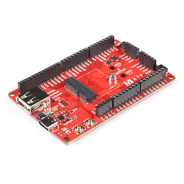
A modern USB-C connector makes programming easy. In addition to the pins broken out, two separate Qwiic-enabled I²C ports allow you to easily daisy chain Qwiic-enabled devices. We've exposed the SWD pins for more advanced users who prefer to use professional tools' power and speed. A USB-A connector is provided for Processor Boards that have USB Host support. A backup battery is provided for processor boards with RTC. If you need a 'lot' of GPIO with a simple-to-program, ready for the market module, the ATP is the fix you need. We've even added a convenient jumper to measure the current consumption for low power testing. Features M.2 Connector Operating Voltage Range ~3.3 V to 6.0 V (via VIN to AP7361C 3.3V Voltage Regulator) 3.3 V (via 3V3) Ports 1x USB type C 1x USB type A Host 2x Qwiic Enabled I²C 1x CAN 1x I²S 2x SPI 2x UARTs 2x Dedicated Analog Pins 2x Dedicated PWM Pins 2x Dedicated Digital Pins 12x General Purpose Input Output Pins 1x SWD 2x5 header 1 mAh battery backup for RTC Buttons Reset Boot LEDs Power 3.3 V Phillips #0 M2.5x3mm screw included
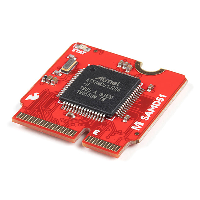
The board provides you with an economical and easy to use development platform if you're needing more power with minimal working space. With the M.2 MicroMod connector, connecting your SAMD51 Processor is a breeze. Simply match up the key on your processor's bevelled edge connector to the key on the M.2 connector and secure it with a screw (included with all Carrier Boards). The SAMD51 is one of the most powerful and economical microcontrollers available so to be able to add it to your MicroMod Carrier Board is a huge advantage for your project! The ATSAMD51J20 utilizes a 32-bit ARM Cortex-M4 processor with Floating Point Unit (FPU), running up to 120MHz, up to 1MB of flash memory, up to 256KB of SRAM with ECC, up to 6 SERCOM interfaces, and other features. This MicroMod SAMD51 even comes flashed with the same convenient UF2 bootloader as the SAMD51 Thing Plus and the RedBoard Turbo. Features ATSAMD51J20 microcontroller 32-bit ARM Cortex-M4F MCU Up to 120MHz CPU speed 1MB flash memory 256 KB SRAM Up to 6 SERCOM interfaces UF2 bootloader
1 x USB dedicated for programming and debug (Host capable) 2 x UARTs 2 x I²C 1 x SPI 1 x CAN 11 x GPIO 2 x Digital Pins 2 x Analog Pins 2 x PWM 128 mbit / 16 MB (external) flash memory Status LED VIN Level ADC
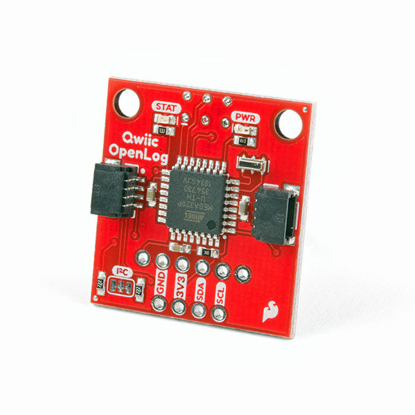
The SparkFun Qwiic OpenLog is the smarter and better looking cousin to the extremely popular OpenLog but now we've ported the original serial based interface to I²C! Thanks to the added Qwiic connectors, you can daisy chain multiple I²C devices and log them all without taking up your serial port. The Qwiic OpenLog can store, or 'log', huge amounts of serial data and act as a black box of sorts to store all the data that your project generates, for scientific or debugging purposes. Utilizing our handy Qwiic system, no soldering is required to connect it to the rest of your system. However, we still have broken out 0.1'-spaced pins in case you prefer to use a breadboard. Like its predecessor, the SparkFun Qwiic OpenLog runs off of an onboard ATmega328, running at 16 MHz thanks to the onboard resonator. The ATmega328 has been sure to feature the Optiboot bootloader loaded, which allows the OpenLog to be compatible with the “Arduino Uno” board setting in the Arduino IDE. It is important to be aware that the Qwiic OpenLog draws approximately 2 mA-6 mA in idle (nothing to record) mode, however, during a full record the OpenLog can draw 20 mA to 23 mA depending on the microSD card being used. The Qwiic OpenLog also supports clock stretching, which means it performs even better than the original and will record data up to 20,000 bytes per second at 400 kHz. As the receive buffer fills up this OpenLog will hold the clock line, letting the master know that it is busy. Once the Qwiic OpenLog is finished with a task, it releases the clock thus allowing the data to continue flowing without corruption. For even better performance the OpenLog Artemis is the tool you need, featuring logging speeds up to 500000 bps. Features Continuous data logging at 20,000 bytes per second without corruption Compatible with high speed 400 kHz I²C Compatible with 64 MB to 32 GB microSD cards (FAT16 or FAT32) Preloaded Uno bootloader so upgrading the firmware is as easy as loading a new sketch Valid I²C Addresses: 0x08 to 0x77 2x Qwiic Connectors Downloads Schematic Eagle Files Hookup Guide Arduino Library GitHub
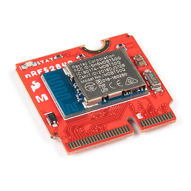
This module includes an integrated trace antenna, fits the IC to an FCC-approved footprint, and includes decoupling and timing mechanisms that would need to be designed into a circuit using the bare nRF52840 IC. The Bluetooth transceiver included on the nRF52840 boasts a BT 5.1 stack. It supports Bluetooth 5, Bluetooth mesh, IEEE 802.15.4 (Zigbee & Thread) and 2.4Ghz RF wireless protocols (including Nordic's proprietary RF protocol) allowing you to pick which option works best for your application. Features ARM Cortex-M4 CPU with a floating-point unit (FPU) 1MB internal Flash -- For all of your program, SoftDevice, and file-storage needs! 256kB internal RAM -- For your stack and heap storage. Integrated 2.4GHz radio with support for: Bluetooth Low Energy (BLE) -- With peripheral and/or central BLE device support Bluetooth 5 -- Mesh Bluetooth! ANT -- If you want to turn the device into a heart-rate or exercise monitor. Nordic's proprietary RF protocol -- If you want to communicate, securely, with other Nordic devices. Every I/O peripheral you could need. USB -- Turn your nRF52840 into a USB mass-storage device, use a CDC (USB serial) interface, and more. UART -- Serial interfaces with support for hardware flow-control if desired. I²C -- Everyone's favourite 2-wire bi-directional bus interface SPI -- If you prefer the 3+-wire serial interface Analogue-to-digital converters (ADC) -- Eight pins on the nRF52840 Mini Breakout support analogue inputs PWM -- Timer support on any pin means PWM support for driving LEDs or servo motors. Real-time clock (RTC) -- Keep close track of seconds and milliseconds, also supports timed deep-sleep features. Three UARTs Primary tied to USB interface. Two hardware UARTs. Two I²C Buses Two SPI Buses Secondary SPI Bus primarily used for Flash IC. PDM Audio Processing Two Analog Inputs Two Dedicated Digital I/O Pins Two Dedicated PWM Pins Eleven General Purpose I/O Pins
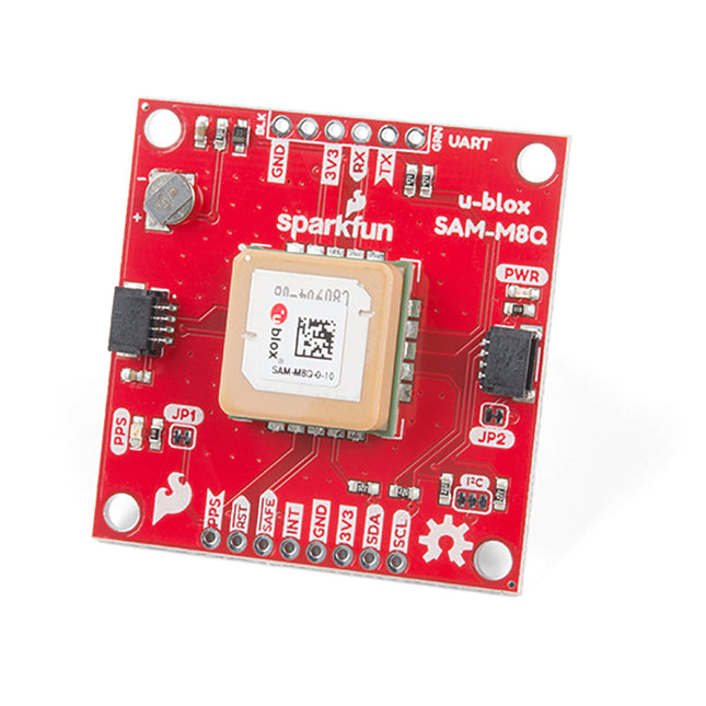
Additionally, this u-blox receiver supports I²C (u-blox calls this Display Data Channel), making it perfect for the Qwiic compatibility, so we don't have to use up our precious UART ports. Utilizing our handy Qwiic system, no soldering is required to connect it to the rest of your system. However, we still have broken out 0.1'-spaced pins if you prefer to use a breadboard. U-blox based GPS products are configurable using the popular but dense, windows program called u-centre. Plenty of different functions can be configured on the SAM-M8Q: baud rates, update rates, geofencing, spoofing detection, external interrupts, SBAS/D-GPS, etc. All of this can be done within the SparkFun Arduino Library! The SparkFun SAM-M8Q GPS Breakout is also equipped with an on-board rechargeable battery that provides power to the RTC on the SAM-M8Q. This reduces the time-to-first fix from a cold start (~30s) to a hot start (~1s). The battery will maintain RTC and GNSS orbit data without being connected to power for plenty of time. Features 72-Channel GNSS Receiver 2.5 m Horizontal Accuracy 18 Hz Max Update Rate Time-To-First-Fix: Cold: 26s Hot: 1s Max Altitude: 50,000 m Max G: ≤4 Max Velocity: 500 m/s Velocity Accuracy: 0.05 m/s Heading Accuracy: 0.3 degrees Time Pulse Accuracy: 30 ns 3.3 V VCC and I/O Current Consumption: ~29 mA Tracking GPS+GLONASS Software Configurable Geofencing Odometer Spoofing Detection External Interrupt Pin Control Low Power Mode Many others! Supports NMEA, UBX, and RTCM protocols over UART or I²C interfaces
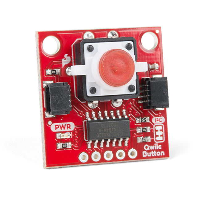
If you need multiple buttons for your project, fear not! Each button has a configurable I²C address, so you can daisy-chain multiple buttons over Qwiic and still address each one individually. We've got an example in our Arduino library that provides a super-easy way to configure your Qwiic Button to whatever I²C address you desire. You can download the library through the Arduino library manager by searching 'SparkFun Qwiic Button', or you can get the GitHub repo as a .zip file and install the library from there. In addition to handling blinking and debouncing, the Qwiic Button has configurable interrupts that can be configured to activate upon a button press or click. We've also taken the liberty of implementing a FIFO queue onboard the Qwiic Button, where it keeps an internal record of when the button was pressed. This means that code on your microcontroller need not waste valuable processing time checking the button's status but instead can run a small function whenever the button is pressed or clicked! For more information on interrupts, check out SparkFun's guide here! Features 12mm Red LED Button rated for 50mA Built-in LED can be configured for your desired level of blinkiness! Each button has a configurable I²C address. FIFO queue
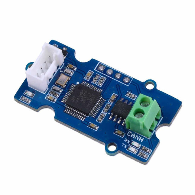
This Grove CAN-BUS Module based on GD32E103 adopts a brand-new design, uses the cost-effective and high-performance GD32E103 microcontroller as the main control and cooperates with a firmware we wrote to complete the function of the serial port to CAN FD. Features
Support CAN communication: Implements CAN FD at up to 5 Mb/s
Easy to program: Support AT command which enables simple serial port programming
Grove ecosystem: 20 x 40 x 10 mm small size, 4-pin Grove connector to plug and play, Arduino compatible This Grove CAN-BUS Module supports CAN FD(CAN with Flexible Data-Rate) communication, which is an extension to the original CAN protocol as specified in ISO 11898-1 that responds to increased bandwidth requirements in automotive networks. In CAN FD, the data rate (i.e. number of bits transmitted per second) is increased to be 5 times faster than the classic CAN (5 Mbit/s for the data payload only, the arbitration bit rate is still limited to 1Mbit/s for compatibility). It supports AT command which enables simple serial port programming. This Grove CAN-BUS Module is based on GD32E103 with a frequency up to 120 MHz. It has a flash size from 64 KB to 128 KB and an SRAM size from 20 KB to 32 KB. Applications Car hacking: allows different parts of the vehicle to talk to each other, including the engine, the transmission, and the brakes. Windows, doors, and mirror adjustment. 3D Printers Building automation Lighting control systems Medical instruments and equipment Specifications MCU GD32E103 UART baud rate Up to 115200 (default 9600) CAN FD baud rate Up to 5 Mb/s Indicator TX and RX led Working voltage 3.3 V Grove connector 4-pin Grove connector to plug and play Size 20 x 40 x 10 mm Downloads Datasheet GitHub
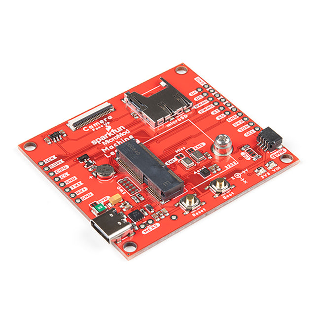
Voice recognition, always-on voice commands, gesture, or image recognition are possible with TensorFlow applications. The cloud is impressively robust, but all-the-time connection requires power and connectivity that may not be available. Edge computing handles discrete tasks such as determining if someone said 'yes' and responds accordingly. The audio analysis is done on the MicroMod combination rather than on the web. This dramatically reduces costs and complexity while limiting potential data privacy leaks. This board features two MEMS microphones (one with a PDM interface, one with an I²S interface), an ST LIS2DH12 3-axis accelerometer, a connector to interface to a camera (sold separately), and a Qwiic connector. A modern USB-C connector makes programming easy and we've exposed the JTAG connector for more advanced users who prefer to use the power and speed of professional tools. We've even added a convenient jumper to measure current consumption for low power testing. Features M.2 MicroMod Keyed-E H4.2mm 65 pins SMD Connector 0.5mm Digital I²C MEMS Microphone PDM Invensense ICS-43434 (COMP) Digital PDM MEMS Microphone PDM Knowles SPH0641LM4H-1 (IC) ML414H-IV01E Lithium Battery for RTC ST LIS2DH12TR Accelerometer (3-axis, ultra-low-power) 24 Pin 0.5mm FPC Connector (Himax camera connector) USB - C Qwiic connector MicroSD socket Phillips #0 M2.5x3mm screw included
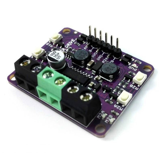
Features Dual channel, Bi-directional control motor driver Support motor voltage from 2.5 V to 9.5 V DC
Maximum current up to 1.0 A continuous and 1.5 A peak (<5 seconds)
5 V Output (200 mA) to power the controller.
Inputs compatible with 1.8 V, 3.3 V and 5 V logic (Arduino, Raspberry Pi, etc). Solid state components provide faster response time and eliminate the wear and tear of mechanical relay Regenerative Braking Speed control PWM frequency up to 20 KHz (Actual output frequency is same as input frequency) Dimension: 43 mm (W) x 35 mm (L) x 14 mm (H) The Problem Faced by Beginners in Driving DC Brushed Motor Maker Drive is designed by taking into account feedback from users, especially 1st time users. If you are a beginner that needs a simple motor driver to drive DC brushed motor for building mobile robot or other purposes, you might come across some of these obstacles: Burning your Motor Driver - Many low cost motor driver does not come with Reserve Polarity Protection and this might result in smoke coming out from the driver if you connect the power in wrong polarity. This gives you a burnt motor driver and of course the waste of money and your precious time. Too Bulky for compact projects - Some motor drivers come with a big heat sink and take up too much space. Hard to test and troubleshoot - With normal motor drivers, beginners face a common problem during building project - difficulty in testing and troubleshooting the circuit. Yes, even with a clear schematic or diagram, the circuit will not work right after you complete the connection. Most of the time, you will need to test or troubleshoot. Without easy to use input and output indicator, you will need to write a program to test the motor driver. And that increases the complexity of debugging as you do not know whether the problem is due to wire connection or coding in your program. Separate Power for Low Voltage Motor - Many low cost motor drivers have an onboard 5 V linear voltage regulator, which is great to power your controller like Arduino. But this linear voltage regulator will not output 5 V if Vin is lower than 7 V. Yet, many small toy motors used in DIY projects are rated at lower than 7 V. These motors are suitable to be powered by two AA or AAA batteries (3 V or less) or single cell Li-ion 18650/Li-Po battery (3.7 V rated voltage). With that, you will need two separate power sources, one for the motors and another one to get stable 5 V output for controller such as Arduino board. Maker Drive is designed to solve the above problems while adding some useful features: Fool Proof - Maker Drive comes with Reverse Polarity Protection at Vin/Vmotor/Vbatt (Power for motor) terminal. With this protection it will greatly reduce the risk of damaging the motor driver Compact Design - Maker Drive is designed to be compact, roughly the size of a passport photo, 43 mm (W) x 35 mm (L) x 14 mm (H) 4 Test Buttons (2 for each channel) - Easily test the motor or your mechanism without any controller or coding. Maker Drive comes with two manual test buttons for each channel. Pressing one of the buttons will drive the output full speed in a direction (if there is motor connected) on respective channel. While another button will drive the output in another direction. These buttons are useful to test the motor direction, connection and operation; even without controller. You can also use these buttons as manual activation button. No programming is needed to use these buttons. 4 Indicator LEDs (2 for each channel) - Easily test your coding and wire connections. With these indicator LEDs, you can check output voltage direction even without connecting the driver to your motor. And combining with the Manual Test Buttons, you can test the Maker Drive easily even without controller and motor connected. You can also easily identify where the error occurs for easy troubleshooting. Of course no programming is needed here either. These LEDs are quite useful for testing and troubleshooting. Buck-boost regulator to produce 5 V output from input voltage as low as 2.5 V- Allows you to power a 5 V controller with 2 AA batteries. Maker Drive can produce output of 5 V with input voltage range, from 2.5 V up to 9.5 V. This 5 V output can supply 200 mA to an external circuit such as a controller (Arduino), saving the trouble of getting another power source for your controller. Now your project can be powered with a single power source. And with the wide input voltage range, you can power Maker Drive with two AA or AAA batteries (1.5 V x 2 = 3 V) or single cell Li-ion or Lipo batteries that have rated voltage of 3.7 V. Although Maker Drive is not an Arduino Shield, it is compatible with a number of Arduino main boards: Arduino Uno R3 Arduino Mega 2560 Arduino Nano Arduino Pro Mini in addition to that, it accepts 1.8 V, 3.3 V & 5 V logic (for control) and is compatible with controllers such as Raspberry Pi, BeagleBone, ESP8266, ESP32, etc. Requirements for the motor you use: DC Brush motor (Two Terminals) Operating voltage from 2.5 V to 9.5 V DC
Rated Current <= 1.0 A
Peak Current <= 1.5 A
Suggested Power Sources 2 x AA/AAA batteries (2 x 1.5 V = 3.0 V) 3 x AA/AAA batteries (3 x 1.5 V = 4.5 V) 4 x AA/AAA batteries (4 x 1.5 V = 6.0 V) 1 x Li-ion 18650 battery (1 x 3.7 V, 3.0 V to 4.2 V) 2 x Li-ion 18650 batteries (2 x 3.7 V = 7.4 V, 6.0 V to 8.4 V) 1 x Li-ion 14500 battery (1 x 3.7 V, 3.0 V to 4.2 V) 2 x Li-ion 14500 batteries (2 x 3.7 V = 7.4 V, 6.0 V to 8.4 V) Documents Datasheet Arduino Sketch: Select PWM_PWM_DUAL under example Fritzing files
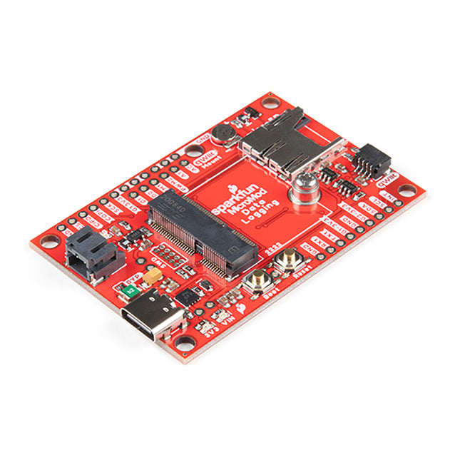
The Data Logging Carrier Board breaks out connections for I²C via a Qwiic connector or standard 0.1'-spaced PTH pins along with SPI and serial UART connections for logging data from peripheral devices using those communication protocols. The Data Logging Carrier Board allows you to control power to both the Qwiic connector on the board and a dedicated 3.3V power rail for non-Qwiic peripherals so you can pick and choose when to power the peripherals you are monitoring the data from. It also features a charging circuit for single-cell Lithium-ion batteries along with a separate RTC battery-backup circuit to maintain power to a real-time clock circuit on your Processor Board. Features M.2 MicroMod Connector microSD socket USB-C Connector 3.3 V 1 A Voltage Regulator Qwiic Connector Boot/Reset Buttons RTC Backup Battery & Charge Circuit Independent 3.3V regulators for Qwiic bus and peripheral add-ons Controlled by digital pins on Processor Board to enable low power sleep modes Phillips #0 M2.5 x 3 mm screw included
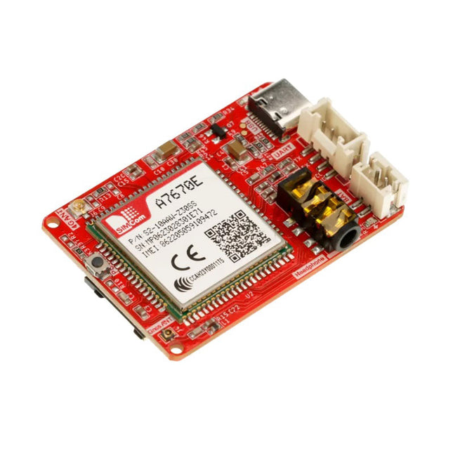
This Crowtail series 4G module is a high-performance LTE Cat1 wireless module. It uses the SIM A7670E communication module from Simcom and communicates through a UART interface, which enables 4G data transmission and voice communication. The module supports multiple LTE bands, including B1/B3/B5/B7/B8/B20, as well as WCDMA and GSM networks. In addition, it supports various protocols such as TCP/IP, FTP, HTTP, and multiple satellite navigation systems such as GPS, GLONASS, and BDS. The module comes with a charging interface and can be powered by a 3.7 V lithium battery or a 5 V USB-C interface. It also has a 3.5 mm headphone jack, and by connecting a headphone with a microphone, it can be used for making and receiving phone calls. Its compact size makes it easy to integrate into various IoT devices and meet various application requirements. Furthermore, its low power consumption and reliable performance are also the reasons why it is widely used in IoT, smart home, automotive, and industrial control fields. Features Integrate the A7670E communication module, enabling 4G data transmission and voice communication with low power consumption and high reliability Supports multiple LTE bands, including B1/B3/B5/B7/B8/B20, as well as WCDMA and GSM networks Supports various protocols such as TCP/IP, FTP, HTTP, and multiple satellite navigation systems such as GPS, GLONASS, and BDS Comes with a charging interface and a headphone jack, which can be used for making and receiving phone calls by connecting a headphone with a microphone Small but powerful, compact size makes it easy to integrate into various IoT devices. Specifications Main Chip: SIM A7670E LTE-FDD: B1/B3/B5/B7/B8/B20 GSM: 900/1800 MHz GSM/GPRS power class EGSM900: 4 (33 dBm ±2 dB) DCS1800: 1 (30 dBm ±2 dB) EDGE power class: EGSM900: E2 (27 dBm ±3 dB) DCS1800 : E1 (26 dBm +3 dB/-4 dB) LTE power class: 3 (23 dBm ±7 dB) Supply Voltage: 4 V ~ 4.2 V Power: 3.8 V LTE(Mbps): 10 (DL)/5 (UL) GPRS/EDGE(Kbps): 236.8 (DL)/236.8 (UL) Protocol: TCP/IP/IPV4/IPV6/Multi-PDP/FTP/FTPS /HTTP/HTTPS/DNS Communication interface: USB / UART Firmware Upgrade: USB/FOTA Support phonebook types: SM/FD/ON/AP/SDN Interfaces: 1x Power button, 1x BAT, 1x UART, 1x USB-C, 1x SIM Card slot Dimensions: 35 x 50 mm Included 1x Crowtail-4G SIM-A7670E 1x 4G GSM NB-IoT Antenna 1x GPS ceramic antenna
Downloads Wiki A7670 AT Command Manual A7670 Datasheet Source Code
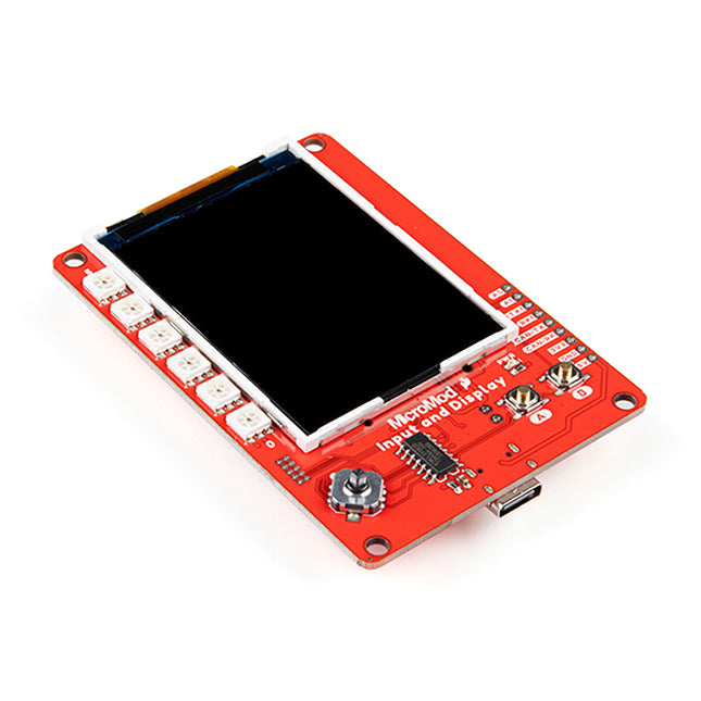
This carrier board combines a 2.4' TFT display, six addressable LEDs, onboard voltage regulator, a 6-pin IO connector, and microSD slot with the M.2 pin connector slot so that it can be used with compatible processor boards in our MicroMod ecosystem. We've also populated this carrier board with Atmel's ATtiny84 with 8kb of programmable flash. This little guy is preprogrammed to communicate with the processor over I²C to read button presses. Features M.2 MicroMod Connector 240 x 320 pixel, 2.4' TFT display 6 Addressable APA102 LEDs Magnetic Buzzer USB-C Connector 3.3 V 1 A Voltage Regulator Qwiic Connector Boot/Reset Buttons RTC Backup Battery & Charge Circuit microSD Phillips #0 M2.5 x 3 mm screw included
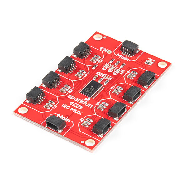
The Qwiic Mux also has eight configurable addresses of its own, allowing for up to 64 I²C buses on a connection. To make it even easier to use this multiplexer, all communication is enacted exclusively via I²C, utilizing our handy Qwiic system. The Qwiic Mux also allows you to change the last three bits of the address byte, allowing for eight jumper selectable addresses if you happen to need to put more than one Qwiic Mux Breakout on the same I²C port. The address can be changed by adding solder to any of the three ADR jumpers. Each SparkFun Qwiic Mux Breakout operates between 1.65 V and 5.5 V, making it ideal for all of the Qwiic boards we produce in house.
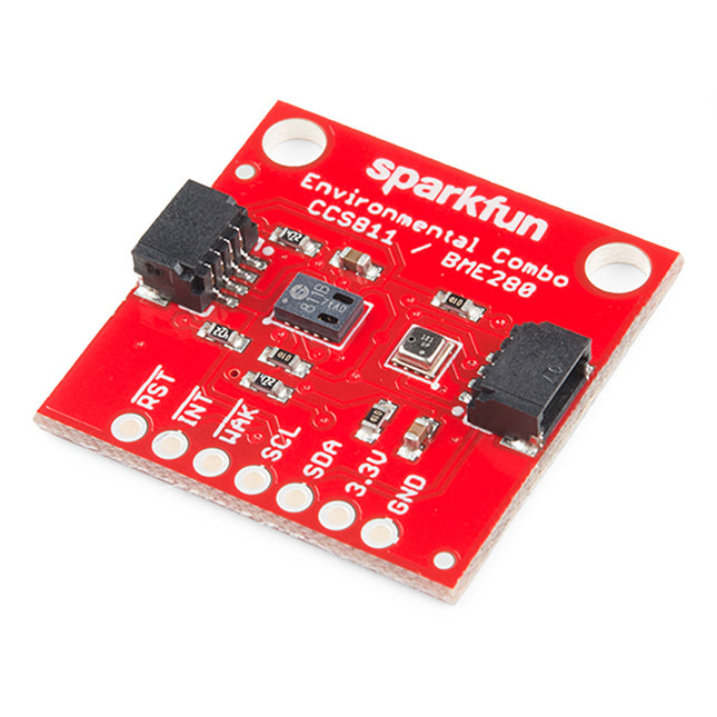
To make it even easier to use this breakout, all communication is enacted exclusively via I²C, utilizing our handy Qwiic system. However, we still have broken out 0.1' spaced pins in case you prefer to use a breadboard. The CCS811 is an exceedingly popular sensor, providing readings for equivalent CO2 (or eCO2) in the parts per million (PPM) and total volatile organic compounds in the parts per billion (PPB). The CCS811 also has a feature that allows it to fine-tune its readings if it has access to the current humidity and temperature. Luckily, the BME280 provides humidity, temperature and barometric pressure! This allows the sensors to work together to give us more accurate readings than they’d be able to provide on their own. We also made it easy to interface with them via I²C. Features Qwiic-Connector Enabled Operation Voltage: 3.3 V Total Volatile Organic Compound (TVOC) sensing from 0 to 1,187 parts per billion eCO2 sensing from 400 to 8,192 parts per million Temp Range: -40C to 85C Humidity Range: 0-100% RH, = -3 % from 20-80% Pressure Range: 30,000Pa to 110,000Pa, relative accuracy of 12Pa, absolute accuracy of 100Pa Altitude Range: 0 to 30,000 feet (9.2 km), relative accuracy of 3.3 feet (1 m) at sea level, 6.6 (2 m) at 30,000 feet
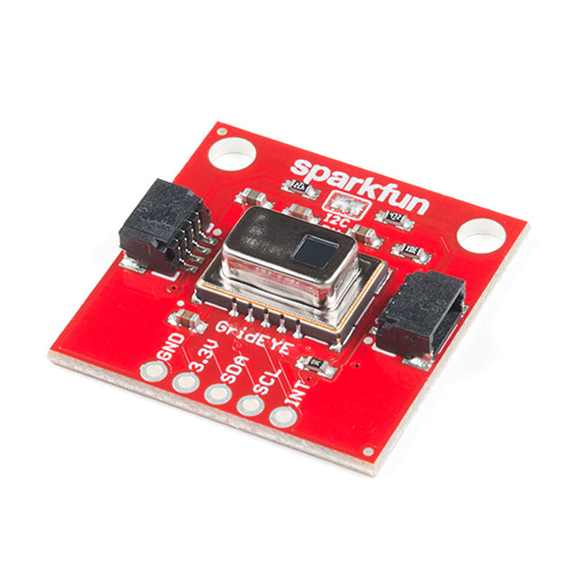
Het is net een thermische camera, alleen in een lagere resolutie. Om het nog gemakkelijker te maken om uw lage-resolutie infrarood beeld te krijgen, verloopt alle communicatie uitsluitend via I2C, gebruik makend van ons handige Qwiic systeem. We hebben echter nog steeds 0.1'-spaced pinnen als u liever een breadboard gebruikt.
De AMG8833 Grid-EYE van Panasonic heeft een nauwkeurigheid van ±2.5°C met een temperatuurbereik van 0°C tot 80°C. Bovendien kan dit IR 'camera' bord menselijke lichaamswarmte detecteren op ongeveer 7 meter of minder en heeft een beeldsnelheid van 10 beelden per seconde tot één beeld per seconde. Het is belangrijk erop te wijzen dat, hoewel deze versie van de Grid-EYE het krachtigste type is met een hoge versterking, hij slechts 3,3 V verdraagt.
Kenmerken
Bedrijfsspanning (opstarten): 1,6 V - 3,6 V
Bedrijfsspanning (tijdwaarneming): 1,5 V - 3,6 V
Stroomverbruik: 4,5 mA
8x8 thermopile serie
Temperatuurbereik: 0°C tot 80°C
Nauwkeurigheid: ±2.5°C
Menselijke Opsporingsafstand: 7m of minder
I2C Adres: 0x69 (open jumper, standaard) of 0x68 (gesloten jumper)
2x Qwiic Aansluitpoorten