Search results for "stepper motor driver circuit"
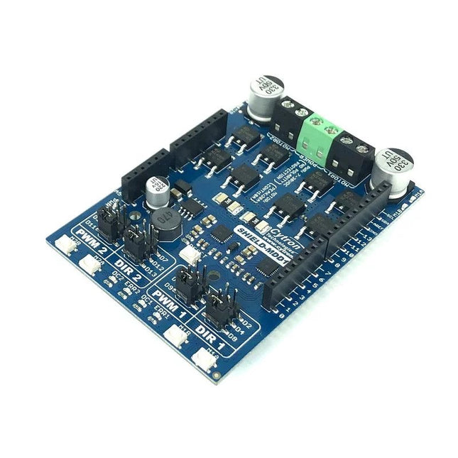
Cytron Cytron 10Amp 7-30 V DC Motor Driver Shield for Arduino (2 Channels)
You can control the motor driver with PWM and DIR inputs. The Arduino pins for these inputs are configurable via jumpers. If the specified pins on Arduino are already used up by other application/shield, you can select another pin easily with the jumper. There is also a possibility to quickly and conveniently test the functionality of the motor driver with the onboard test buttons and output LEDs. Buck regulator which produces 5 V output is also available to power the Arduino mainboard, which eliminates the need of extra power supply for the Arduino mainboard. The board also offers various protection features. Overcurrent protection prevents the motor driver from damage when the motor stalls or an oversized motor is hooked up. When the motor is trying to draw current more than what the motor driver can support, the motor current will be limited at the maximum threshold. Assisted by temperature protection, the maximum current limiting threshold is determined by the board temperature. The higher the board temperature, the lower the current limiting threshold. As a result, the motor driver delivers its full potential depending on the current conditions without damaging any MOSFETs. Features Shield for Arduino form factor Bidirectional control for two brushed DC motors Control one unipolar/bipolar stepper motor Operating Voltage: DC 7 V to 30 V Maximum Motor Current: 10 A continuous, 30 A peak Buck regulator to produce 5 V output (500 mA max) Buttons for quick testing LEDs for motor output state Selectable Arduino pins for PWM/DIR inputs. PWM/DIR inputs compatible with 1.8 V, 3.3 V and 5 V logic PWM frequency up to 20 kHz (Output frequency is same as input frequency). Overcurrent protection with active current limiting Temperature protection Undervoltage shutdown Possible applications Mobile Robot Automated Guided Vehicle (AGV) Solar Tracker Game Simulator Automation Machine Downloads Datasheet Sample Code 3D CAD Files Packing List 1x 10Amps 7V-30V DC Motor Driver Shield for Arduino (2 Channels) MDD010
€ 29,95
Members € 26,96
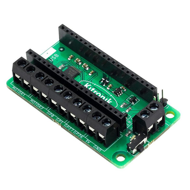
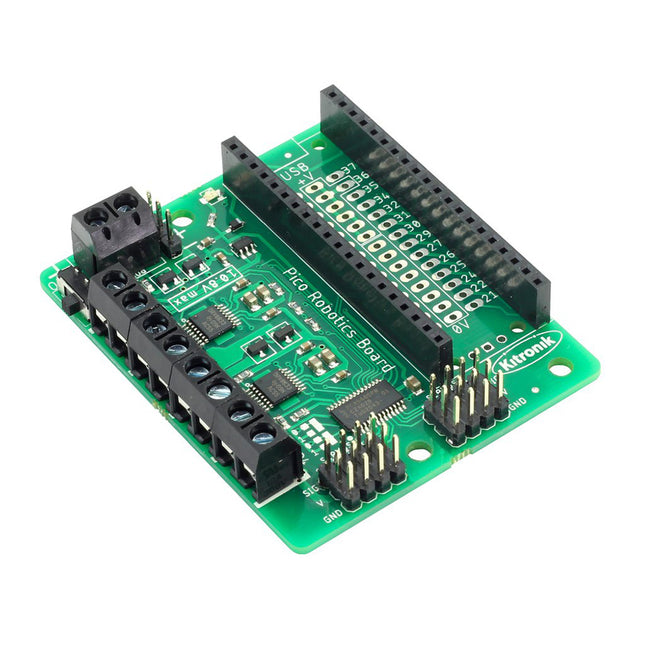
Kitronik Kitronik Motor Driver Board for Raspberry Pi Pico
This board allows the Raspberry Pi Pico (connected via pin header) to drive two motors simultaneously with full forward, reverse & stop control, making it ideal for Pico controlled buggy projects. Alternatively, the board can be used to power a stepper motor. The board features the DRV8833 motor driver IC, which has built-in short circuit, over current and thermal protection. The board has 4 external connections to GPIO pins and a 3 V and GND supply from the Pico. This allows for additional IO options for your buggy builds that can be read or controlled by the Pico. In addition there is an on/off switch and power status LED, allowing you to see at a glance if the board is powered up and save your batteries when your project is not in use. To use the motor driver board, the Pico should have a soldered pin header and be inserted firmly into the connector. The board produces a regulated supply that is fed into the 40-way connector to power the Pico, removing the need to power the Pico directly. The motor driver board is powered via either screw terminals or a servo style connector. Kitronik has developed a micro-python module and sample code to support the use of the Motor Driver board with the Pico. This code is available in the GitHub repo. Features A compact yet feature-packed board designed to sit at the heart of your Raspberry Pi Pico robot buggy projects. The board can drive 2 motors simultaneously with full forward, reverse, and stop control. It features the DRV8833 motor driver IC, which has built-in short circuit, over current and thermal protection. Additionally, the board features an on/off switch and power status LED. Power the board via a terminal block style connector. The 3V and GND pins are also broken out, allowing external devices to be powered. Code it with MicroPython via an editor such as the Thonny editor. Dimensions: 63 mm (L) x 35 mm (W) x 11.6 mm (H) Download Datasheet
€ 15,95
Members € 14,36
Elektor Digital Elektor March/April 2023 (PDF)
Elektor GREEN and GOLD members can download their digital edition here. Not a member yet? Click here. Cloc 2.0The Alarm Clock You've Always Wanted RP2040 PIO in PracticeExperiments Using the RP2040’s Programmable I/O Poor Man's ChipTweakerWe Have (Low-Budget) Ways of Making You Talk USB True Random Number GeneratorTwo PICs for the Price of One AVR Pimp My MicSelf-Designed Level Booster FFT with a MaixduinoFrequency spectrum display From Life’s ExperienceDesign Logic (or Non-Logic) UCN5804 Stepper Motor DriverPeculiar Parts, the Series Circuit Simulation With Micro-CapFirst Steps in a Complicated World PAUL Award 2022Young Technical Talents and Their Creative Solutions My First Software-Defined RadioBuilt in Less Than 15 Minutes Microcontroller Documentation Explained (Part 1)Datasheet structure What’s Next for AI and Embedded Systems?Tools, Platforms, and Writer Replacements Digitizing Vertical Farming Infographics: Embedded and AI Today and Tomorrow An Introduction to TinyML JetCarrier96A Versatile NVIDIA Jetson Development System Case Study: Taking EV Charging Global with a Universal RFID Solution High-Performance in Every ClassComputer-on-Module Standards Starting Out in ElectronicsLet’s Get Active! I²C Communication Using Node.js and a Raspberry PiSee Your Sensor Data in a Browser Video Output with Microcontrollers (2)VGA and DVI Output The Metronom Real-Time Operating SystemAn RTOS for AVR Processors DVI on the RP2040An Interview with Luke Wren, Chip Developer at Raspberry Pi Display HAT MiniShow the Weather Forecast on Raspberry Pi! WEEF 2022 Awards: Celebrate the Good Hexadoku
€ 7,50
Members € 6,75
Elektor March/April 2023
Elektor GREEN and GOLD members can download their digital edition here. Not a member yet? Click here. Cloc 2.0The Alarm Clock You've Always Wanted RP2040 PIO in PracticeExperiments Using the RP2040’s Programmable I/O Poor Man's ChipTweakerWe Have (Low-Budget) Ways of Making You Talk USB True Random Number GeneratorTwo PICs for the Price of One AVR Pimp My MicSelf-Designed Level Booster FFT with a MaixduinoFrequency spectrum display From Life’s ExperienceDesign Logic (or Non-Logic) UCN5804 Stepper Motor DriverPeculiar Parts, the Series Circuit Simulation With Micro-CapFirst Steps in a Complicated World PAUL Award 2022Young Technical Talents and Their Creative Solutions My First Software-Defined RadioBuilt in Less Than 15 Minutes Microcontroller Documentation Explained (Part 1)Datasheet structure What’s Next for AI and Embedded Systems?Tools, Platforms, and Writer Replacements Digitizing Vertical Farming Infographics: Embedded and AI Today and Tomorrow An Introduction to TinyML JetCarrier96A Versatile NVIDIA Jetson Development System Case Study: Taking EV Charging Global with a Universal RFID Solution High-Performance in Every ClassComputer-on-Module Standards Starting Out in ElectronicsLet’s Get Active! I²C Communication Using Node.js and a Raspberry PiSee Your Sensor Data in a Browser Video Output with Microcontrollers (2)VGA and DVI Output The Metronom Real-Time Operating SystemAn RTOS for AVR Processors DVI on the RP2040An Interview with Luke Wren, Chip Developer at Raspberry Pi Display HAT MiniShow the Weather Forecast on Raspberry Pi! WEEF 2022 Awards: Celebrate the Good Hexadoku
€ 10,95
Members € 9,86
Kitronik Kitronik Robotics Board for Raspberry Pi Pico
The Robotics Board features 2 Dual H Bridge Motor Driver ICs. These are capable of driving 2 standard motors or 1 stepper motor each, with full forward, reverse, and stop control. There are also 8 servo outputs, capable of driving standard and continuous rotation servos. They can all be controlled by the Pico using the I²C protocol, via a 16 channel driver IC. The IO break out provides connections to all the unused pins on the Pico. The 27 available I/O pins allow other devices, such as sensors or ZIP LEDs, to be added to the board. Power is provided via either a terminal block or servo style connector. The supply is then controlled by an on/off power switch to the board and there is also a green LED to indicate when the board has power. The board then produces a regulated 3.3V supply which is fed into the 3 V and GND connections to power the connected Pico. This removes the need to power the Pico separately. The 3 V and GND pins are also broken out on the header, which means external devices can also be powered. To use the robotics board, the Pico should be firmly inserted into the dual row pin socket on the board. Ensure the Pico is inserted with the USB connector at the same end as the power connectors on the robotics board. This will allow access to all of the board functions and each pin is broken out. Features A compact yet feature-packed board designed to sit at the heart of your Raspberry Pi Pico robotics projects. The board can drive 4 motors (or 2 stepper motors) and 8 servos, with full forward, reverse, and stop control. It also features 27 other I/O expansion points and Power and Ground connections. The I²C communication lines are also broken out allowing other I²C compatible devices to be controlled. This board also features an on/off switch and power status LED. Power the board via either a terminal block or servo style connector. The 3V and GND pins are also broken out on the Link header, allowing external devices to be powered. Code it with MicroPython or via an editor such as the Thonny editor. 1 x Kitronik Compact Robotics Board for Raspberry Pi Pico Dimensions: 68 x 56 x 10 mm Requires Raspberry Pi Pico board
€ 24,95
Members € 22,46
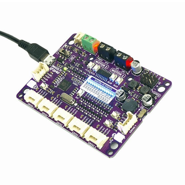
Cytron Cytron Maker Pi RP2040 - Robotics with Raspberry Pi RP2040
Cytron Maker Pi RP2040 features the first microcontroller designed by Raspberry Pi – RP2040, embedded on a robot controller board. This board comes with dual channel DC motor driver, 4 servo motor ports and 7 Grove I/O connectors, ready for your next DIY robot / motion control project. Now you can build robot, while trying out the new RP2040 chip. The DC motor driver onboard is able to control 2x brushed DC motors or 1x bipolar/unipolar stepper motor rated from 3.6 V to 6 V, providing up to 1 A current per channel continuously. The built-in Quick Test buttons and motor output LEDs allow functional test of the motor driver in a quick and convenient way, without the need of writing any code. Vmotor for both DC and servo motors depends on the input voltage supplied to the board. Maker Pi RP2040 features all the goodness of Cytron's Maker series products. It too has lots of LEDs useful for troubleshooting (& visual effects), is able to make quite some noise with the onboard piezo buzzer and comes with push buttons ready to detect your touch. There are three ways to supply power to the Maker Pi RP2040 – via USB (5 V) socket, with a single cell LiPo/Li-Ion battery or through the VIN (3.6-6 V) terminals. However only one power source is needed to power up both controller board and motors at a time. Power supply from all these power sources can all be controlled with the power on/off switch onboard. Cytron Maker Pi RP2040 is basically the Raspberry Pi Pico + Maker series' goodness + Robot controller & other useful features. Therefore this board is compatible with the existing Pico ecosystem. Software, firmware, libraries and resources that are developed for Pico should work seamlessly with Cytron Maker Pi RP2040 too. CircuitPython is preloaded on the Maker Pi RP2040 and it runs a simple demo program right out-of-the-box. Connect it to your computer via USB micro cable and turn it on, you will be greeted by a melody tune and LEDs running light. Press GP20 and GP21 push buttons to toggle the LEDs on/off, while controlling any DC and servo motors connected to it to move and stop. With this demo code, you get to test the board the moment you receive it! While connected to your computer, a new CIRCUITPY drive appears. Explore and edit the demo code (code.py & lib folder) with any code editor you like, save any changes to the drive and you shall see it in action in no time. That's why we embrace CircuitPython – it's very easy to get started. Wish to use other programming lauguages? Sure, you are free to use MicroPython and C/C++ for Pico/RP2040. For those of you who loves the Arduino ecosystem, please take a look at this official news by Arduino and also the unofficial Pico Arduino Core by Earle F. Philhower. Features Powered by Rapberry Pi RP2040 Dual-core Arm Cortex-M0+ processor 264 KB internal RAM 2 MB of Flash memory the exact same specifications with Raspberry Pi Pico Robot controller board 4x Servo motors 2x DC motors with quick test buttons Versatile power circuit Automatic power selection: USB 5 V, LiPo (1-cell) or Vin (3.6-6 V) Built-in 1-cell LiPo/Li-Ion charger (over-charged & over-discharged protection) Power on/off switch 13x Status indicator LEDs for GPIO pins 1x Piezo buzzer with mute switch 2x Push button 2x RGB LED (Neopixel) 7x Grove ports (flexible I/O options: digital, analog, I²C, SPI, UART...) Preloaded with CircuitPython by default Mouting holes 4x 4.8 mm mounting hole (LEGO pin compatible) 6x M3 screw hole
€ 16,95
Members € 15,26


