Search results for "labs"

The Arduino-Inside Measurement Lab
An 8-in-1 test & measurement instrument for the electronics workbench A well-equipped electronics lab is crammed with power supplies, measuring devices, test equipment and signal generators. Wouldn‘t it be better to have one compact device for almost all tasks? Based on the Arduino, a PC interface is to be developed that’s as versatile as possible for measurement and control. It simply hangs on a USB cable and – depending on the software – forms the measuring head of a digital voltmeter or PC oscilloscope, a signal generator, an adjustable voltage source, a frequency counter, an ohmmeter, a capacitance meter, a characteristic curve recorder, and much more. The circuits and methods collected here are not only relevant for exactly these tasks in the "MSR" electronics lab, but many details can also be used within completely different contexts.
€ 29,95
Members € 26,96

Elektor Digital The Arduino-Inside Measurement Lab (E-book)
An 8-in-1 test & measurement instrument for the electronics workbench A well-equipped electronics lab is crammed with power supplies, measuring devices, test equipment and signal generators. Wouldn‘t it be better to have one compact device for almost all tasks? Based on the Arduino, a PC interface is to be developed that’s as versatile as possible for measurement and control. It simply hangs on a USB cable and – depending on the software – forms the measuring head of a digital voltmeter or PC oscilloscope, a signal generator, an adjustable voltage source, a frequency counter, an ohmmeter, a capacitance meter, a characteristic curve recorder, and much more. The circuits and methods collected here are not only relevant for exactly these tasks in the "MSR" electronics lab, but many details can also be used within completely different contexts.
€ 24,95
Members € 19,96
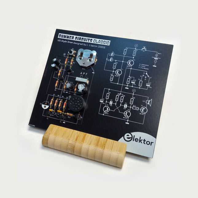
Elektor Labs Elektor US-Style Siren Kit
A great way to explain the workings of an electronic circuit is to position the discrete parts on the board exactly as in the schematic. Press the button and this 'Elektor Classic' responds with 1 of 3 siren sounds: police, ambulance, or fire brigade. The kit is composed of through-hole parts only and includes a wooden desktop stand. A full explanation of the circuit operation appears on the back of the circuit board. Features Realistic Sound from Onboard Speaker Unique PCB Layout Equals Schematic Elektor Heritage Circuit Symbols Tried & Tested by Elektor Labs Educational & Geeky Project Through-Hole Parts Only Included Printed Circuit Board All Components Wooden Desktop Stand
€ 34,95€ 24,95
Members identical
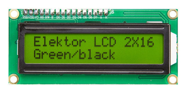
Elektor Labs Standard 2x16 Character back-lit LCD
Standard 2x16 LCD (see Elektor Labs Preferred Parts - ELPP) with the following specifications: 2 rows, 16 characters wide 5 x 7 dots font and cursor Yellow-green LCD with yellow-green LED backlight HD44780 equivalent LCD controller High contrast Readable in sunlight 16 pin Connection port is 2.54 mm (0.1') pitch, single row for easy breadboarding and wiring pinning (left-to-right): 1-14,A,K Single LED backlight included; Easily dimmed with a resistor or via PWM; Uses much less power than electroluminescent backlights Can be fully controlled with only 6 digital lines(in 4-bit bus mode) 5V DC operating voltage Module dimension: 80 x 36 x 10 mm Viewing area size: 64.5x 15 mm
€ 7,95
Members € 7,16

Elektor Labs Elektor Tapir E-Smog Detector Kit
Ultrasensitive wideband magnetic/electromagnetic field detector This ultra sensitive wideband “E-smog” detector adds two senses to help you track down noise that’s normally inaudible. TAPIR also makes a great project to build since the enclosure is the PCB proper. TAPIR detects electric as well as magnetic fields at high frequencies. The PCB is ingenuously designed to double as a shielded case. Each of the two antennas that can be connected to TAPIR is optimized for one type of field. Magnetic fields are detected with a ferrite-cored coil, and electric fields with a rod antenna, which is easily constructed from a length of stiff wire. Using TAPIR is dead easy. Connect the headphones, the selected antenna and switch on. Move the antenna around any suspect area and you’ll hear different types of noise and noise levels with each electrical device, depending on the type and frequency of the emitted field. Features Ultrasensitive Wideband 'E-smog' Detector PCB Doubles as Project Housing Tried & Tested by Elektor Labs Educational & Geeky Project Easy to solder SMD Parts Online Illustrated Construction Manual Included Printed Circuit Board All Components Antenna and Headphones
€ 39,95€ 29,95
Members identical
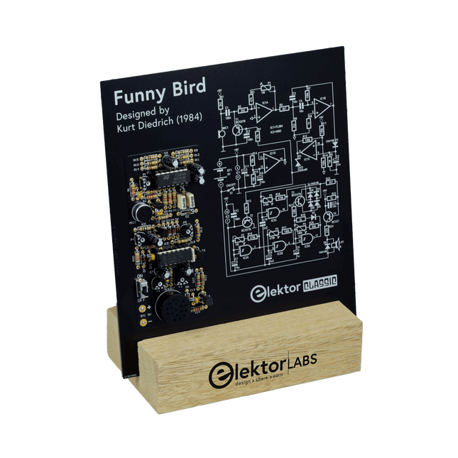
Elektor Labs Elektor Funny Bird Kit
Whistle And It Chirps Back At You! Although birds of all sorts are lovingly owned and watched by many people, sadly most of them have not yet learnt to communicate with us. This all-electronic bird takes a step in the right direction: when you whistle at it, it chirps back! Features Responds to Whistling Adjustable Bird Sounds (Tone and Length) Elektor Heritage Circuit Symbols Tried & Tested by Elektor Labs Educational & Geeky Project Through-Hole Parts Only Included Printed Circuit Board All Components Wooden Stand Bill of Materials Resistors R1,R2 = 2.2kΩ R3,R4,R13 = 47kΩ R5 = 4.7kΩ R6 = 3.3kΩ R7,R10,R11,R12,R17 = 100kΩ R8,R19,R23 = 1kΩ R9 = 1MΩ R14,R15 = 10kΩ R16,R18 = 470kΩ R20 = 68kΩ R21 = 10MΩ R22 = 2.7kΩ R24 = 22Ω P1,P2 = 1MΩ P3,P5 = 470kΩ P4 = 100kΩ Capacitors C1,C2,C12 = 100nF C3,C4 = 10nF C5 = 22μF, 16V C6,C7,C11 = 10μF, 16V C8 = 2.2μF, 100V C9 = 1μF, 50V C10 = 2.2nF C13 = 10nF Semiconductors D1,D3,D4,D5,D6,D7,D8 = 1N4148 D2 = 3V3 zener diode T1,T2 = BC557B T3 = BC547B T4 = BC327-40 IC1 = TL084CN IC2 = 4093 Miscellaneous BT1 = wired battery clip for 6LR61/PP3 LS1 = miniature loudspeaker, 8Ω, 0.5W S1 = switch, slide, SPDT MIC1 = electret microphone PCB 230153-1 v1.1
€ 44,95€ 37,95
Members identical
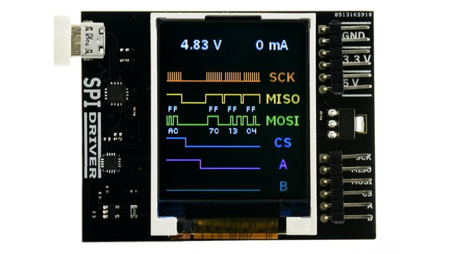
Excamera Labs SPIDriver
SPIDriver shows you what’s happening on the SPI bus in real time, so no more guessing about the bus state. Its purpose is to make understanding the functioning of SPI hardware more intuitive. It's useful if you're into debugging hardware or simply introduce a class to SPI for the first time.You can directly control LEDs and LCD displays just by having SPIDriver and you won't have to deal with microcontrollers. It's also a useful tool for examining, backing up and cloning an SPI flash as well as reading and writing SPI flash in circuit.SPIDriver is also applicable if you want to drive, test and evaluate different displays.With the help of current and voltage monitoring you'll be able to detect electrical problems at early stages. Thanks to the included color coded wires you can hook SPIDriver up without much effort; no pinout diagram required. It includes 3.3 V and 5 V supplies for your device, plus a high-side current meter.SPIDriver comes with software to control it from: a GUI the command-line C and C++ using a single source file Python 2 and 3, using a module Technical features Live display shows you exactly what it’s doing all the time Sustained SPI transfers at 500 Kbps USB line voltage monitor to detect supply problems, to 0.01 V Target device high-side current measurement, to 5 mA Two auxiliary output signals, A and B Two dedicated power outlines: of 3.3 V and 5 V All signals color coded to match jumper colors All signals are 3.3 V, and are 5 V tolerant Uses an FTDI USB serial adapter, and Silicon Labs automotive-grade EFM8 controller Also reports uptime, temperature, and running CRC of all traffic All sensors and signals controlled using a simple serial protocol GUI, command-line, C/C++, and Python 2/3 host software provided for Windows, Mac, and Linux Details Maximum power out current: up to 470 mA Signal current: up to 10 mA Device current: up to 25 mA Dimensions: 61 mm x 49 mm x 6 mm Interface: USB 2.0, micro USB connector Contents (SPIDriver Core) 1x SPIDriver 1x Set of hookup jumpers
€ 49,95
Members € 44,96
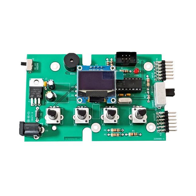
Elektor Labs Elektor Super Servo Tester kit
The Elektor Super Servo Tester can control servos and measure servo signals. It can test up to four servo channels at the same time. The Super Servo Tester comes as a kit. All the parts required to assemble the Super Servo Tester are included in the kit. Assembling the kit requires basic soldering skills. The microcontroller is already programmed. The Super Servo Tester features two operating modes: Control/Manual and Measure/Inputs. In Control/Manual mode the Super Servo Tester generates control signals on its outputs for up to four servos or for the flight controller or ESC. The signals are controlled by the four potentiometers. In Measure/Inputs the Super Servo Tester measures the servo signals connected to its inputs. These signals may come from for instance an ESC, a flight controller, or the receiver or another device. The signals are also routed to the outputs to control the servos or the flight controller or ESC. The results are shown on the display. Specifications Operating modes Control/Manual & Measure/Inputs Channels 3 Servo signal inputs 4 Servo signal outputs 4 Alarm Buzzer & LED Display 0.96' OLED (128 x 32 pixels) Input voltage on K5 7-12 VDC Input voltage on K1 5-7.5 VDC Input current 30 mA (9 VDC on K5, nothing connected to K1 and K2) Dimensions 113 x 66 x 25 mm Weight 60 g Included Resistors (0.25 W) R1, R3 1 kΩ, 5% R2, R4, R5, R6, R7, R9, R10 10 kΩ, 5% R8 22 Ω, 5% P1, P2, P3, P4 10 kΩ, lin/B, vertical potentiometer Capacitors C1 100 µF 16 V C2 10 µF 25 V C3, C4, C7 100 nF C5, C6 22 pF Semiconductors D1 1N5817 D2 LM385Z-2.5 D3 BZX79-C5V1 IC1 7805 IC2 ATmega328P-PU, programmed LED1 LED, 3 mm, red T1 2N7000 Miscellaneous BUZ1 Piezo buzzer with oscillator K1, K2 2-row, 12-way pinheader, 90° K5 Barrel jack K4 1-row, 4-way pin socket K3 2-row, 6-way boxed pinheader S1 Slide switch DPDT S2 Slide switch SPDT X1 Crystal, 16 MHz 28-way DIP socket for IC2 Elektor PCB OLED display, 0.96', 128 x 32 pixels, 4-pin I²C interface Links Elektor Magazine Elektor Labs
€ 49,95€ 42,95
Members € 38,66
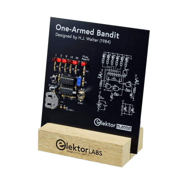
Elektor Labs Elektor One-armed Bandit Kit
Pull Down Lever For Highest Score! This Elektor Circuit Classic from 1984 shows a playful application of CMOS 400x series logic ICs in combination with LEDs, a highly popular combination at the time. The project imitates a spinning-digit type slot machine. The Game To play the game, first agree on the number of rounds. Player 1 actuates the switch lever as long as desired and releases it. The LEDs then show the score which is the sum of the 50-20-10-5 digits lit up. If the Play Again! LED lights, Player 1 has another, “free” round. If not, it’s Player 2’s turn. The players keep tab of their scores, and the highest score wins. Features LEDs Indicate Score Multi-Player and Play Again! Elektor Heritage Circuit Symbols Tried & Tested by Elektor Labs Educational & Geeky Project Through-Hole Parts Only Included Printed Circuit Board All Components Wooden Stand Bill of Materials Resistors (5%, 250 mW) R1,R2,R3,R4 = 100kΩ R5,R6,R7,R8,R9,R10 = 1kΩ Capacitors C1 = 4.7nF, 10%, 50V, 5mm C2 = 4.7μF, 10%, 63V, axial C3,C4 = 100nF, 10 %, 50V, ceramic X7R, 5mm Semiconductors LED1-LED6 = red, 5mm (T1 3/4) IC1 = 74HC4024 IC2 = 74HC132 Miscellaneous S1 = switch, toggle, 21mm lever, SPDT, momentary S2 = switch, tactile, 24V, 50mA, 6x6mm S3 = switch, slide, SPDT IC1,IC2 = IC socket, DIP14 BT1 = PCB-mount CR2032 battery retainer clip Desktop Stand PCB 230098-1 Not included: BT1 = CR2032 coin cell battery
€ 39,95€ 33,95
Members identical
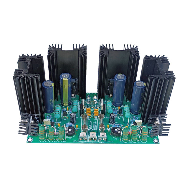
Elektor Labs Elektor ±40 V Linear Voltage Regulator Kit
An alternative power supply for the Elektor Fortissimo-100 Power Amplifier For those who object to a switch-mode power supply for the Fortissimo-100 Power Amplifier, this kit yields a linear, symmetrical, voltage regulator marked by low dropout voltage, high output current, and excellent stability – all obtained from discrete components. Bearing in mind that nearly all high-performance audio power amplifiers benefit from a stabilized power supply, this linear power supply is specifically designed for a symmetrical output voltage of ±40 V and peak currents of 13 A (15 A peak achievable). As an example, the average current drawn by a Fortissmo-100 amp driving a 3 Ω load is 4 A per regulator. Specifications Input voltage range 52 V DC (low power usage) to 43 V DC Output voltage range approx. 38.9 V DC to 41.4 V DC (theoretically)38.6 V DC to 41.1 V DC (measured) Dropout voltage at 6 A 42 V Dropout voltage at 9.5 A 43 V Dropout voltage at 13.5 A 44 V Max. current 15 A peak (half sinewave), 4.8 A (average) SOAR protection 15 A at 45 V DC in Ripple rejection >60 dB (@ 5 A DC load) No-load input current 27 mA (@ 52 V DC input) Included PCB All parts including heatsinks
€ 84,95
Members € 76,46
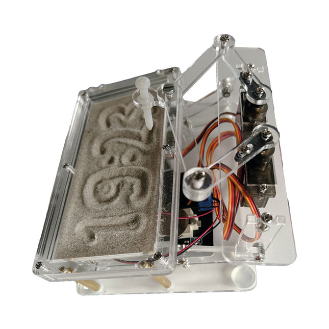
Elektor Labs Sand Clock Kit (based on Raspberry Pi Pico)
Raspberry Pi-based Eye Catcher A standard sand clock just shows how time passes. In contrast, this Raspberry Pi Pico-controlled sand clock shows the exact time by “engraving” the four digits for hour and minute into the layer of sand. After an adjustable time the sand is flattened out by two vibration motors and everything begins all over again. At the heart of the sand clock are two servo motors driving a writing pen through a pantograph mechanism. A third servo motor lifts the pen up and down. The sand container is equipped with two vibration motors to flatten the sand. The electronic part of the sand clock consists of a Raspberry Pi Pico and an RTC/driver board with a real-time clock, plus driver circuits for the servo motors. A detailed construction manual is available for downloading. Features Dimensions: 135 x 110 x 80 mm Build time: 1.5 to 2 hours approx. Included 3x Precut acrylic sheets with all mechanical parts 3x Mini servo motors 2x Vibration motors 1x Raspberry Pi Pico 1x RTC/driver board with assembled parts Nuts, bolts, spacers, and wires for the assembly Fine-grained white sand
€ 62,95
Members € 56,66
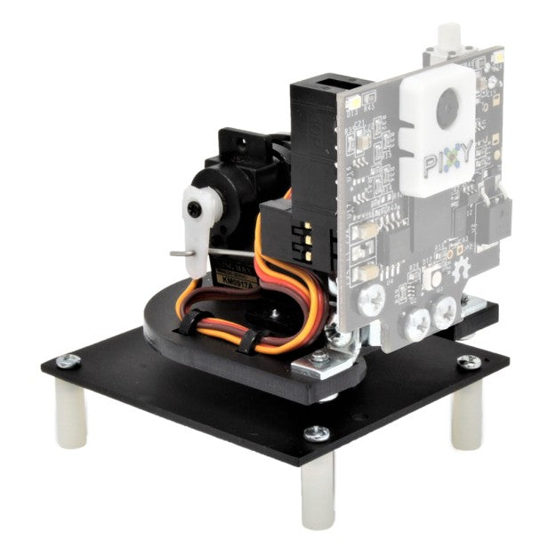
Charmed Labs Pixy2 CMUcam Pan/Tilt Kit
This is a kit for a pan-tilt mechanism explicitly designed for Pixy2. After assembling the kit and connecting it to Pixy2, you'll be able to follow colored objects using the Pan/Tilt demo. It includes two laser-cut plastic pieces for the base, two different servos for the pan and tilt axes, and all the mounting hardware and cable ties you will need to assemble. Features The pan-tilt mechanism for Pixy2 is redesigned, making it smaller and faster than the pan-tilt for the original Pixy. All necessary hardware is included. The pan-tilt base is attached directly to an Arduino with Arduino-compatible hole-pattern and includes stand-offs and fasteners. Several pan-tilt demos are provided that can run using either Arduino, Raspberry Pi or stand-alone (no controller). Complete assembly instructions
€ 39,95
Members € 35,96


