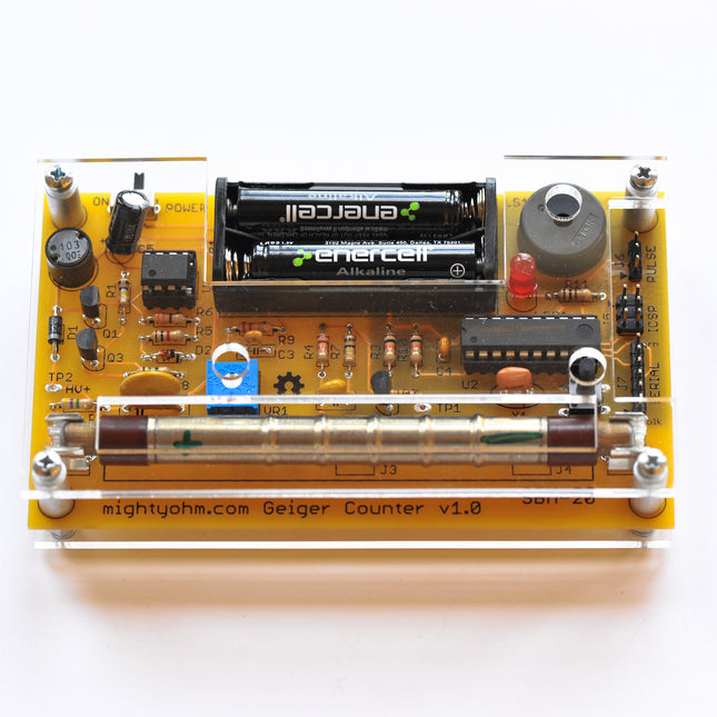
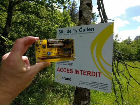
Have you ever wondered if the objects in your house are radioactive or not? Does the apple in your fridge give off radiation? Are the books on your shelves giving off gamma rays? You can easily find that out by building your Geiger counter! Thanks to the serial logging function you can track exposure over time, and you can use the mute button to detect radiation without any noise. Detect beta and gamma radiation with your own portable Geiger counter! Features 100% Open Source Hardware! Sensitive to beta and gamma radiation LED and piezo speaker alert you to detected radioactivity. Mute button for silent operation. An ATtiny2313 microcontroller brain that is begging to be hacked! Support for several common Geiger-Müller tubes: SI-3BG, SI-1G, and SBM-20. HV supply can be adjusted from ~300-600 V. Headers for serial (9600 baud), in-circuit programming of the AVR microcontroller, and pulse output (to connect the Geiger counter to other stuff!) Serial data logging! Counts per second (CPS), counts per minute (CPM), and equivalent dose are reported via the serial port once a second. Included Geiger counter kit incl. PCB and all parts 1x SBM-20 Geiger-Müller tube 1x Laser cut acrylic case Downloads Assembly Instructions Case Assembly Instructions Design Files Source Code Usage Instructions
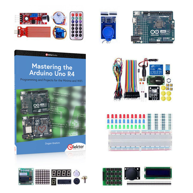
The project book, written by well-known Elektor author Dogan Ibrahim, holds many software- and hardware-based projects especially developed for the Arduino Uno Experimenting Kit. The kit comes with the Arduino Uno R4 Minima, several LEDs, sensors, actuators, and other components. The purpose of the kit is to make a flying start with hardware and software aspects of projects designed around the Arduino Uno microcontroller system. The projects given in this guide are fully evaluated and working and fully employ all the supplied components. A block diagram, a circuit diagram, an extensive program listing, and a complete program description is given for every project in the guide. Included 1x Arduino Uno R4 Minima
1x RFID reader module 1x DS1302 clock module 1x 5 V stepper motor 1x '2003' stepper motor drive board 5x Green LED 5x Yellow LED 5x Red LED 2x Rocker switch 1x Flame sensor 1x LM35 sensor module 1x Infrared receiver 3x Light-dependent resistors (LDRs) 1x IR remote controller 1x Breadboard 4x Pushbutton (with four caps) 1x Buzzer 1x Piezo sounder 1x Adjustable resistor (potentiometer) 1x 74HC595 shift register 1x 7-segment display 1x 4-digit 7-segment display 1x 8x8 Dot-matrix display 1x 1602 / I²C LCD module 1x DHT11 Temperature and humidity module 1x Relay module 1x Sound module Set of Dupont cables Set of Breadboard cables 1x Water sensor 1x PS2 Joystick 5x 1 k-ohm resistor 5x 10 k-ohm resistor 5x 220-ohm resistor 1x 4x4 keypad module 1x 9g Servo (25 cm) 1x RFID card 1x RGB module 1x 9 V battery DC jack Project book (326 pages) Over 80 Projects in the Book Hardware Projects with LEDs Blinking LED – using the on-board LED Blinking LED – using an external LED LED flashing SOS Alternately blinking LEDs Chaser-LEDs Chasing LEDs 2 Binary counting LEDs Random flashing LEDs – Christmas lights Button controlled LED Controlling the LED flashing rate – external interrupts Reaction timer LED color wand RGB fixed colors Traffic lights Traffic lights with pedestrian crossings Using the 74HC595 shift register – binary up counter Using the 74HC595 shift register – random flashing 8 LEDs Using the 74HC595 shift register – chasing LEDs Using the 74HC595 shift register – turn ON a specified LED Using the 74HC595 shift register – turn ON specified LEDs 7-Segment LED Displays 7-Segment 1-digit LED counter 7-Segment 4-digit multiplexed LED display 7-Segment 4-digit multiplexed LED display counter – timer interrupts 7-Segment 4-digit multiplexed LED display counter – blanking leading zeroes 7-Segment 4-digit multiplexed LED display – reaction timer Timer interrupt blinking onboard LED Liquid Crystal Displays (LCDs) Display text on the LCD Scrolling text on the LCD Display custom characters on the LCD LCD based conveyor belt goods counter LCD based accurate clock using timer interrupts LCD dice Sensors Analog temperature sensor Voltmeter On/Off temperature controller Darkness reminder – using a light-dependent resistor (LDR) Tilt detection Displaying water level Water level controller Water flooding detector with buzzer Sound detection sensor – control the relay by clapping hands Flame sensor – fire detection with relay output Temperature and humidity display Generating musical tones – melody maker The RFID Reader Finding the Tag ID RFID door lock access with relay The 4x4 Keypad Display the pressed key code on the Serial Monitor Integer calculator with LCD Keypad door security lock with relay The Real-Time Clock (RTC) Module RTC with Serial Monitor RTC with LCD Temperature and humidity display with time stamping Setting and displaying the current time Periodic interrupt every 2 seconds The Joystick Reading analog values from the joystick 8x8 LED Matrix Displaying shapes Motors: Servo and Stepper Test-rotate the servo Servo sweep Joystick-controlled servo Rotate the motor clockwise and then anticlockwise The Digital to Analog Converter (DAC) Generating a square wave with 2 V amplitude Generate a sine wave Sine wave sweep frequency generator Generate sine wave whose frequency changes with potentiometer Generate a square wave with frequency of 1 kHz and amplitude of 1 V Using the EEPROM, the Human Interface Device, and PWM Keyboard control to launch Windows programs LED dimming using PWM The Arduino Uno R4 WiFi Using LED matrix 1 – creating a large + shape Creating images by setting bits Using LED matrix 2 – creating a large + shape Animation – displaying a word Controlling the Arduino Uno R4 WiFi on-board LED from a smartphone using UDP Serial Communications Receiving ambient temperature from an Arduino Uno R3 Using an Arduino Uno Simulator A simple project simulation – flashing LED Displaying text on LCD LCD seconds counter The CAN bus Arduino Uno R4 WiFi to Arduino Uno R4 Minima CAN bus communication Sending the temperature readings over the CAN bus Infrared Receiver and Remote Controller Decoding the IR remote control codes Remote relay activation/deactivation Infrared remote stepper motor control
Program and build RPi Pico-based ham station utilities, tools, and instruments Although much classical HF and mobile equipment is still in use by large numbers of amateurs, the use of computers and digital techniques has now become very popular among amateur radio operators. Nowadays, anyone can purchase a €5 Raspberry Pi Pico microcontroller board and develop many amateur radio projects using the “Pico” and some external components. This book is aimed at amateur radio enthusiasts, Electronic Engineering students, and anyone interested in learning to use the Raspberry Pi Pico to shape their electronic projects. The book is suitable for beginners in electronics as well as for those with wide experience. Step-by-step installation of the MicroPython programming environment is described. Some knowledge of the Python programming language is helpful to be able to comprehend and modify the projects given in the book. The book introduces the Raspberry Pi Pico and gives examples of many general-purpose, software-only projects that familiarize the reader with the Python programming language. In addition to the software-only projects tailored to the amateur radio operator, Chapter 6 in particular presents over 36 hardware-based projects for “hams”, including: Station mains power on/off control Radio station clock GPS based station geographical coordinates Radio station temperature and humidity Various waveform generation methods using software and hardware (DDS) Frequency counter Voltmeter / ammeter / ohmmeter / capacitance meter RF meter and RF attenuators Morse code exercisers RadioStation Click board Raspberry Pi Pico based FM radio Using Bluetooth and Wi-Fi with Raspberry Pi Pico Radio station security with RFID Audio amplifier module with rotary encoder volume control Morse decoder Using the FS1000A TX-RX modules to communicate with Arduino
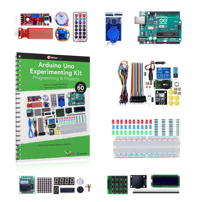
The project book, written by well-known Elektor author Dogan Ibrahim, holds many software- and hardware-based projects especially developed for the Arduino Uno Experimenting Kit. The kit comes with an Arduino Uno board, several LEDs, sensors, actuators, and other components. The purpose of the kit is to make a flying start with hardware and software aspects of projects designed around the Arduino Uno microcontroller system. The projects given in this guide are fully evaluated and working and fully employ all the supplied components. A block diagram, a circuit diagram, an extensive program listing, and a complete program description is given for every project in the guide. Included in the kit 1x Arduino Uno Rev3 board
1x RFID reader module 1x DS1302 clock module 1x 5 V stepper motor 1x '2003' stepper motor drive board 5x Green LED 5x Yellow LED 5x Red LED 2x Rocker switch 1x Flame sensor 1x LM35 sensor module 1x Infrared receiver 3x Light-dependent resistors (LDRs) 1x IR remote controller 1x Breadboard 4x Pushbutton (with four caps) 1x Buzzer 1x Piezo sounder 1x Adjustable resistor (potentiometer) 1x 74HC595 shift register 1x 7-segment display 1x 4-digit 7-segment display 1x 8x8 Dot-matrix display 1x 1602 / I²C LCD module 1x DHT11 Temperature and humidity module 1x Relay module 1x Sound module Set of Dupont cables Set of Breadboard cables 1x Water sensor 1x PS2 Joystick 5x 1 k-ohm resistor 5x 10 k-ohm resistor 5x 220-ohm resistor 1x 4x4 keypad module 1x 9g Servo (25 cm) 1x RFID card 1x RGB module 1x 9 V battery DC jack Project book (237 pages) Over 60 Projects in the Book Hardware Projects with LEDs Blinking LED – using the onboard LED Blinking LED – using an external LED LED flashing SOS Alternately-blinking LEDs Chasing LEDs Chasing LEDs 2 Binary counting LEDs Random flashing LEDs – Christmas lights Button controlled LED Controlling the LED flashing rate – external interrupts Reaction timer LED color wand RGB fixed colors Traffic lights Traffic lights with pedestrian crossings Using the 74HC595 shift register – binary up counter Using the 74HC595 shift register – randomly flashing 8 LEDs Using the 74HC595 shift register – chasing LEDs Using the 74HC595 shift register – turn ON a specified LED Using the 74HC595 shift register – turn ON specified LEDs 7-Segment LED Displays 7-Segment 1-digit LED counter 7-Segment 4-digit multiplexed LED display 7-Segment 4-digit multiplexed LED display counter – timer interrupts 7-Segment 4-digit multiplexed LED display counter – eliminating the leading zeroes 7-Segment 4-digit multiplexed LED display – reaction timer Timer interrupt blinking onboard LED Liquid Crystal Displays (LCDs) Display text on the LCD Scrolling text on the LCD Display custom characters on the LCD LCD based conveyor belt goods counter LCD-based accurate clock using timer interrupts LCD dice Sensors Analog temperature sensor Voltmeter On/Off temperature controller Darkness reminder using a light-dependent resistor (LDR) Tilt detection Water-level sensor Displaying water levels Water level controller Flooding detector with buzzer Sound detection sensor – relay control by hand clapping Flame sensor – fire detection with relay output Temperature and humidity display Generating musical tones with the melody maker The RFID Reader Finding the Tag ID RFID door lock access control with relay The 4x4 Keypad Display the pressed key code on the Serial Monitor Integer calculator with LCD Keypad door security lock with relay The Real-Time Clock (RTC) Module RTC with Serial Monitor RTC with LCD Temperature and humidity display with time stamping The Joystick Reading joystick analog values 8x8 LED Matrix Displaying shapes Motors Test-rotate the servo Servo sweep Joystick-controlled servo Rotate the motor clockwise and then anticlockwise Infrared Receiver and Remote Controller Unit Decoding the IR remote control codes Remote relay activation/deactivation Infrared remote stepper motor control
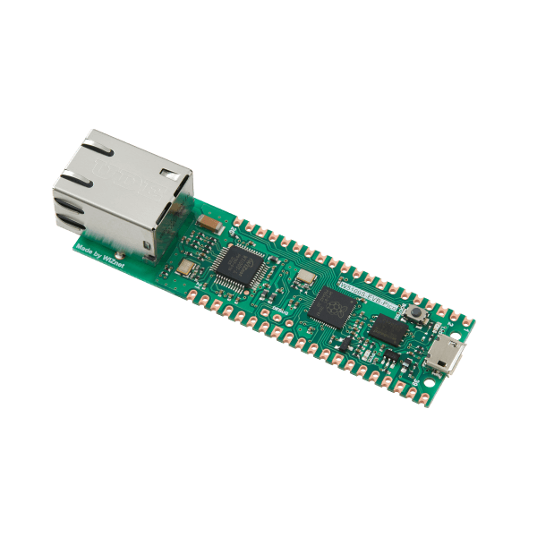
Features RP2040 microcontroller with 2 MB Flash Dual-core cortex M0+ at up to 133 MHz 264 KB multi-bank high performance SRAM External Quad-SPI Flash with eXecute In Place (XIP) High performance full-crossbar bus fabric 30 multi-function General Purpose IO (4 can be used for ADC) 1.8-3.3 V IO Voltage (NOTE. Pico IO voltage is fixed at 3.3 V) 12-bit 500 ksps Analogue to Digital Converter (ADC) Various digital peripherals 2× UART, 2× I²C, 2× SPI, 16× PWM channels 1× Timer with 4 alarms, 1× Real Time Counter 2× Programmable IO (PIO) blocks, 8 state machines total Flexible, user-programmable high-speed IO Can emulate interfaces such as SD Card and VGA Includes W5100S Supports Hardwired Internet Protocols: TCP, UDP, WOL over UDP, ICMP, IGMPv1/v2, IPv4, ARP, PPPoE Supports 4 Independent Hardware SOCKETs simultaneously Internal 16 KB Memory for TX/ RX Buffers SPI Interface Micro-USB B port for power and data (and for reprogramming the Flash) 40 pin 21x51 'DIP' style 1mm thick PCB with 0.1' through-hole pins also with edge castellations 3-pin ARM Serial Wire Debug (SWD) port 10 / 100 Ethernet PHY embedded Supports Auto Negotiation Full / Half Duplex 10 / 100 Based Built-in RJ45 (RB1-125BAG1A) Built-in LDO (LM8805SF5-33V) Downloads RP2040 Datasheet W5100S Datasheet Schematic & Part list & Gerber File C/C++ Examples CircuitPython Examples
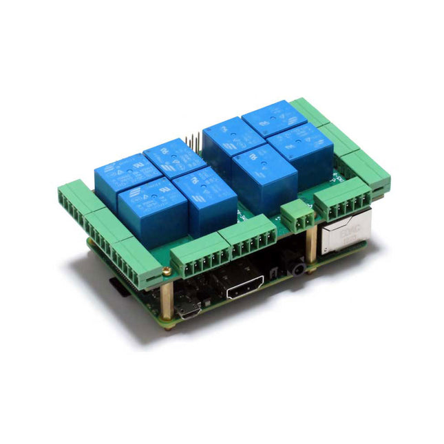
The Home Automation HAT uses only pluggable connectors. In addition, the latest release (V4.0 and up) has two new communication ports: 1-Wire and RS485. The card uses only 5 V power. On-board step-up power supply generates 12 V to power the 0-10 V analog outputs. A general purpose push-button, wired directly to a Raspberry Pi GPIO pin, can be used to shut down Raspberry Pi without a keyboard, or to force any output to a desired state. Ideal solution for your Raspberry Pi Home Automation projects. Read temperatures in up to 8 zones with analog inputs. Control your heating and cooling system with the 8 onboard relays. Use the 8 optically isolated digital inputs for your security system. Activate the hardware watchdog to monitor and power cycle the Raspberry Pi in case of software lockup. Control four-light systems with the four PWM open-drain outputs (you supply external power up to 24 V). Control four light dimmers using 0-10 V outputs. Compatibility The card is compatible with all Raspberry Pi versions from Zero to 4. It shares the I²C bus using only two of the Raspberry Pi’s GPIO pins to manage all eight cards. This feature leaves the remaining 24 GPIOs available for the user. Power Requirements The Home Automation card needs 5 V to operate and can be powered from Raspberry Pi or from its own pluggable connector. The onboard relay coils are also powered from the 5 V. An on-board 5V to 12V step-up power supply generates the voltage to drive the 0-10 V analog outputs. A local 3.3 V regulator powers the rest of the circuitry. The card needs 50 mA to operate with all relays off. Each relay needs up to 80 mA to turn on. Relays The 8 on-board relays have contacts brought out to heavy duty pluggable connectors, which make the card easy to use when multiple cards are stacked up. Relays are grouped in two sections of four relays each, with one common terminal and one N-O contact for each relay. Relays are rated 10 A/24 VDC and 250 VAC, but due to the board geometry limitation, the relays can switch only 3 A and 24 V, AC or DC. Status LEDs show when RELAYS are ON or OFF. Stacking Multiple Cards Up to eight Home Automation cards can be stacked on your Raspberry Pi. Each card is identified by jumpers you install to indicate the level in the stack. Cards can be installed in any order. The three position jumper on the upper right corner of the card selects the stack level. Features Eight relays with status LEDs and and N.O contacts Eight layer stackable Eight 12-bit A/D inputs, 250 Hz sample rate Four 13-bit DAC outputs (0-10 V dimmers) Four PWM 24 V/4 A open-drain outputs Eight optically isolated digital inputs Contact closure/Event counters up to 500 Hz Four Quadrature Encoder inputs 26 GPIOs from Raspberry Pi available 1-WIRE and RS485 communication ports Pluggable Connectors 26-16 AWG for all ports On-board hardware watchdog On-board resettable fuse Reverse power supply protection Brass stand-offs, screws and nuts included Hardware self-test with loop-back cable Open source hardware, schematics available 32-bit Processor running at 64 MHz Uses only I²C port (address 0x28..0x2f ), all GPIO pins available Specifications Power supply: Pluggable Connector, 5 V/3 A Power consumption: 50 mA (all relays off), 700 mA (all relays on) On board resettable fuse: 3 A Open Drain outputs: maximum 3 A, 24 V Relays 1,2,3,4,5,8: N-O contacts, 6 A/24 VAC or DC Relays 6,7: 3 A/24 VAC or DC Analog Inputs: Maximum input voltage: 3 V Input Impedance: 50 KΩ Resolution: 12 bits Sample rate: 250 samples/sec. DAC Outputs: Resistive load: Minimum 1 KΩ Accuracy: ±1% Opto-isolated Digital Inputs: Input Forward Current: Typical 5 mA, maximum 50 mA Input Series Resistor: 1K Input Reverse Voltage: 5 V Input Forward Voltage: 25 V @ 10 mA Isolation Resistance: Minimum 1012 Ω Included Home Automation stackable Card for Raspberry Pi with self-test Card Mounting hardware 4x M2.5x18 mm male-female brass standoffs 4x M2.5x5 mm brass screws 4x M2.5 brass nuts 2x Stack level Jumpers All required Connector Plugs Laminated Plastic Card showing IO Pinout Downloads User's Guide Open Source Hardware Schematic 2D CAD Drawing Command Line Python Libraries Node-RED Nodes Domoticz Plugin OpenPLC
Program and build RPi Pico-based ham station utilities, tools, and instruments Although much classical HF and mobile equipment is still in use by large numbers of amateurs, the use of computers and digital techniques has now become very popular among amateur radio operators. Nowadays, anyone can purchase a €5 Raspberry Pi Pico microcontroller board and develop many amateur radio projects using the “Pico” and some external components. This book is aimed at amateur radio enthusiasts, Electronic Engineering students, and anyone interested in learning to use the Raspberry Pi Pico to shape their electronic projects. The book is suitable for beginners in electronics as well as for those with wide experience. Step-by-step installation of the MicroPython programming environment is described. Some knowledge of the Python programming language is helpful to be able to comprehend and modify the projects given in the book. The book introduces the Raspberry Pi Pico and gives examples of many general-purpose, software-only projects that familiarize the reader with the Python programming language. In addition to the software-only projects tailored to the amateur radio operator, Chapter 6 in particular presents over 36 hardware-based projects for “hams”, including: Station mains power on/off control Radio station clock GPS based station geographical coordinates Radio station temperature and humidity Various waveform generation methods using software and hardware (DDS) Frequency counter Voltmeter / ammeter / ohmmeter / capacitance meter RF meter and RF attenuators Morse code exercisers RadioStation Click board Raspberry Pi Pico based FM radio Using Bluetooth and Wi-Fi with Raspberry Pi Pico Radio station security with RFID Audio amplifier module with rotary encoder volume control Morse decoder Using the FS1000A TX-RX modules to communicate with Arduino
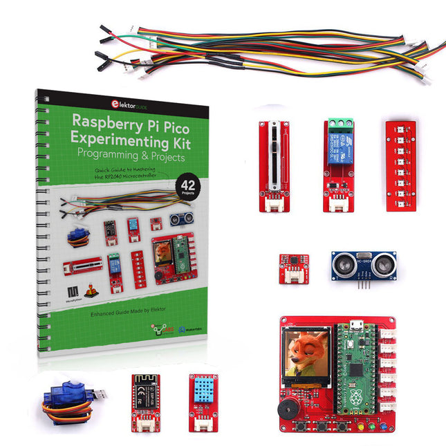
The project book, written by well-known Elektor author Dogan Ibrahim, is an introduction to using the Raspberry Pi Pico Experimenting Kit. The kit is based on the Raspberry Pi Pico processor and includes several on-board as well as external sensors, and an actuator. The kit is programmed using the MicroPython programming language. The Thonny development environment (IDE) is used in all the projects in the book. All the projects given in the book have been fully tested and are working. No prior programming or electronic experience are required to follow the projects.The book’s fully evaluated projects feature all the supplied components. Each project includes a block diagram, a circuit diagram, a full program listing, and a complete program description.Included in the bundle
Raspberry Pi Pico RP2040
Pico Expansion Board
1.44-inch TFT LCD with ST7735 driver
3x Pushbutton input
3x LED output
1x Active buzzer
6x Interfaces (UART/GPIO/I²C/ADC) Grove-compatible
Powered by Micro-USB
8 Modules
MPU6050 6-axis IMU
DHT11 humidity & temperature sensor
10 A relay
SG90 servo
Slide potentiometer
Serial-to-WiFi (ESP8266) module
Ultrasonic range sensor
8-bit RGB addressable LED (WS2818) module
Project book (178 pages)
42 Projects in the BookBoard-Hardware-Based Projects
Flashing an on-board LED
Flashing SOS
Flashing LED – using a timer
Alternately flashing LEDs
Pushbutton control
Changing the LED flashing rate using pushbutton interrupts
Binary counting LEDs
Randomly flashing yellow, green, and blue LEDs
Chasing LEDs
Reaction timer
Buttons and LEDs
The TFT Display
Second counter
Event counter
Reaction timer
Display LED and button status
Temperature and humidity – display in Thonny window
Temperature and humidity – LED output
Temperature and humidity – display on TFT
ON/OFF temperature control
ON/OFF temperature control – setting the desired temperature
Voltmeter
Changing the brightness of an LED
Ultrasonic distance measurement - display in Thonny window
Ultrasonic distance measurement - display on TFT
Height of a person (stadiometer)
Ultrasonic reverse-parking aid with buzzer
Ultrasonic liquid level controller
Melody maker
Servo motor control
Accurate servo motor control
WS2812 LED strip light show - state machine approach
WS2812 LED strip light show – using the neopixel library
WS2812 LED strip show – another neopixel library example
Displaying 3 dimensions of acceleration
A car’s maximum acceleration – using the TFT display
Level display using the gyroscope
MPU6050 temperature display
TFT display test
TFT bitmap display
Using the WiFi
Connect to the local Wi-Fi network and display the IP address
Controlling an LED from a smartphone using Wi-Fi
Displaying the temperature on a smartphone using Wi-Fi
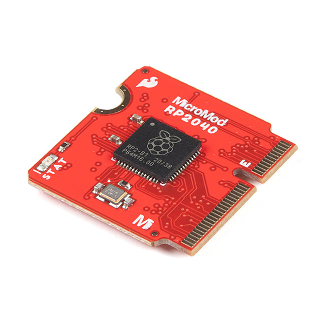
The RP2040 utilizes dual ARM Cortex-M0+ processors (up to 133MHz): 264kB of embedded SRAM in six banks 6 dedicated IO for SPI Flash (supporting XIP) 30 multifunction GPIO: Dedicated hardware for commonly used peripherals Programmable IO for extended peripheral support Four 12-bit ADC channels with internal temperature sensor (up to 0.5 MSa/s) USB 1.1 Host/Device functionality The RP2040 is supported with C/C++ and MicroPython cross-platform development environments, including easy access to runtime debugging. It has a UF2 boot and floating-point routines baked into the chip. The built-in USB can act as both device and host. It has two symmetric cores and high internal bandwidth, making it useful for signal processing and video. While the chip has a large internal RAM, the board includes an additional external flash chip. Features Dual Cortex M0+ processors, up to 133 MHz 264 kB of embedded SRAM in 6 banks 6 dedicated IO for QSPI flash, supporting execute in place (XIP) 30 programmable IO for extended peripheral support SWD interface Timer with 4 alarms Real-time counter (RTC) USB 1.1 Host/Device functionality Supported programming languages MicroPython C/C++
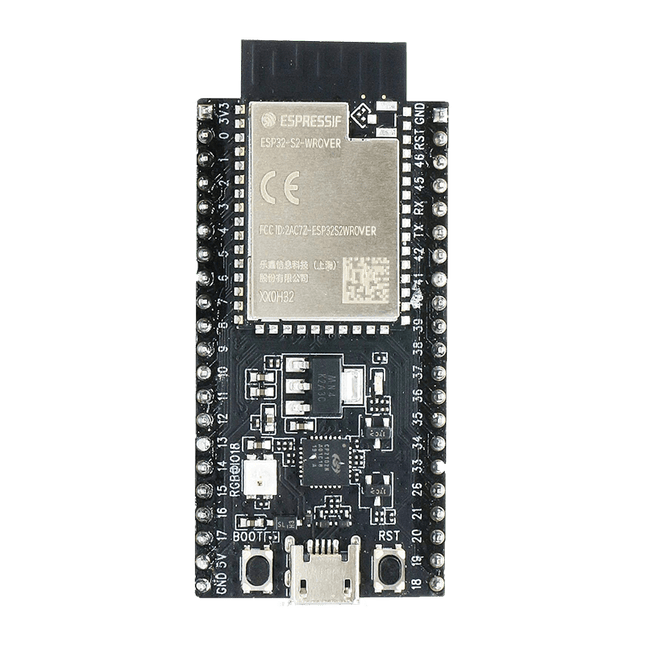
ESP32-S2-Saola-1R is a small-sized ESP32-S2 based development board. Most of the I/O pins are broken out to the pin headers on both sides for easy interfacing. Developers can either connect peripherals with jumper wires or mount ESP32-S2-Saola-1R on a breadboard.ESP32-S2-Saola-1R is equipped with the ESP32-S2-WROVER module, a powerful, generic Wi-Fi MCU module that has a rich set of peripherals. It is an ideal choice for a wide variety of application scenarios relating to Internet of Things (IoT), wearable electronics and smart home. The board a PCB antenna and features a 4 MB external SPI flash and an additional 2 MB SPI Pseudo static RAM (PSRAM).FeaturesMCU
ESP32-S2 embedded, Xtensa® single-core 32-bit LX7 microprocessor, up to 240 MHz
128 KB ROM
320 KB SRAM
16 KB SRAM in RTC
WiFi
802.11 b/g/n
Bit rate: 802.11n up to 150 Mbps
A-MPDU and A-MSDU aggregation
0.4 µs guard interval support
Center frequency range of operating channel: 2412 ~ 2484 MHz
Hardware
Interfaces: GPIO, SPI, LCD, UART, I²C, I²S, Camera interface, IR, pulse counter, LED PWM, TWAI (compatible with ISO 11898-1), USB OTG 1.1, ADC, DAC, touch sensor, temperature sensor
40 MHz crystal oscillator
4 MB SPI flash
Operating voltage/Power supply: 3.0 ~ 3.6 V
Operating temperature range: –40 ~ 85 °C
Dimensions: 18 × 31 × 3.3 mm
Applications
Generic Low-power IoT Sensor Hub
Generic Low-power IoT Data Loggers
Cameras for Video Streaming
Over-the-top (OTT) Devices
USB Devices
Speech Recognition
Image Recognition
Mesh Network
Home Automation
Smart Home Control Panel
Smart Building
Industrial Automation
Smart Agriculture
Audio Applications
Health Care Applications
Wi-Fi-enabled Toys
Wearable Electronics
Retail & Catering Applications
Smart POS Machines