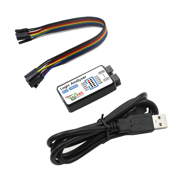
This USB Logic Analyzer is an 8-channel logic analyzer with each input dual purposed for analog data recording. It is perfect for debugging and analyzing signals like I²C, UART, SPI, CAN and 1-Wire. It operates by sampling a digital input connected to a device under test (DUT) at a high sample rate. The connection to the PC is via USB. Specifications Channels 8 digital channels Maximum sampling rate 24 MHz Maximum input voltage 0 V ~ 5 V Operating temperature 0°C ~ 70°C Input impedance 1 MΩ || 10 pF Supported protocols I²C, SPI, UART, CAN, 1-Wire, etc. PC connection USB Dimensions 55 x 28 x 14 mm Included USB Logic Analyzer (8-ch, 24 MHz) USB Cable Jumper Wire Ribbon Cable Downloads Software
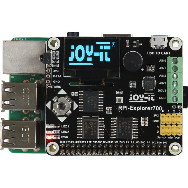
The JOY-iT Explorer 700 Expansion Board for Raspberry Pi expansion board has the following functions:
Pin-Header to put directly on the Raspberry Pi B+, 2B, 3B or 4B
UART interface: connect easily UART modules like for example RS232, RS485, USB to UART (TTL-cable)
AD/DA IO interface: connected cable via screws definable
1-WIRE interface: to connect a 1-WIRE device
Sensor interface: digital and analogue sensors can be connected
0.96 inch OLED display: SSD1306 Driver, 128 x 64 Pixel, SPI interface
Buzzer
USB to UART, converter with CP2102 chipset (mini USB-Port)
PCF8591: 8-bit analog / digital converter, I²C interface
BMP180: sensor for atmospheric pressure, temperature and height over normal zero, I²C interface
PCF8574: I/O Chip for I²C interface
DS3231: high precision RTC chip, I²C interface
Power LED
Programmable LED
Joystick
LFN0038K IR infrared receiver
Interfaces
UART, AD/DA: connected cables can be fixed with screws, 1-Wire, Sensor
Display
0.96“ OLED Display (SSD1306 Driver, 128x64 Pixel)
Dimensions
85 mm x 56 mm x 17 mm
Weight
30 g
For more information, check out the user manual here.
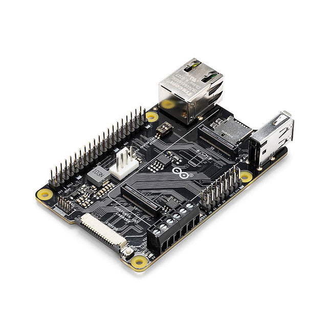
Portenta HAT Carrier is a reliable and robust carrier that transforms Portenta X8 into an industrial single board computer compatible with Raspberry Pi HATs and cameras. It is ideal for multiple industrial applications such as building automation and machine monitoring.Compatible also with Portenta H7 and Portenta C33, Portenta HAT Carrier provides easy access to multiple peripherals – including CAN, Ethernet, microSD and USB – and further extends any Portenta application.It is great for prototyping and ready for scaling up, it extends the features found on a typical Raspberry Pi Model B. Debug quickly with dedicated JTAG pins and keeps heat manageable under intense workloads with a PWM fan connector. Control actuators or read analog sensors via the additional 16x analog I/Os. Add industrial machine vision solutions to any project by leveraging the onboard camera connector.Features
Add Raspberry Pi HATs to your Portenta projects
Quickly access CAN, USB, and Ethernet peripherals
Leverage onboard MicroSD card to log data
Enjoy simple debugging through the onboard JTAG pins
Easily control actuators and read sensors via 16x analog I/Os
Leveraging the onboard camera connector for machine vision
Portenta takes you from prototype to high-performancePortenta HAT Carrier offers you a frictionless Linux prototyping experience and unlocks the ability for integrated real-time MCU solutions. Portenta HAT Carrier extends Portenta SOMs for faster, easier and more efficient testing for your ideas while also ensuring the capabilities and industrial-grade performances the Portenta range is known for.Extend the Raspberry Pi ecosystem for commercial applicationsCombine the ease of use, accessibility and incredible support from both the Arduino and Raspberry Pi communities for your next project with the carrier designed to combine and extend MPU and MCU applications for the development of advanced commercial solutions.Specifications
Connectors
High-density connectors compatible with Portenta products
1x USB-A female connector
1x Gigabit Ethernet connector (RJ45)
1x CAN FD with onboard transceiver
1x MIPI Camera connector
1x MicroSD card slot
1x PWM fan connector
40-pin header connector allowing compatibility with Raspberry Pi HATs
16-pin analog header connectors, including:
8x analog inputs
1x GPIO
1xUART without flow control
2x PWM pins
1x LICELL pin for Portenta's RTC power
Interfaces
CAN FD
UART
SAI
ANALOG
GPIO
SPI
I²C
I²S
PWM
Debugging
Onboard 10x pin 1.27 mm JTAG connector
Power
From onboard screw terminal block allowing:
7-32 V power supply, powering both the carrier and the connected Portenta
5 V power supply
From USB-C on Portenta
From 5 V on 40-pin header connector
Dimensions
85 x 56 mm
Downloads
Datasheet
Schematics
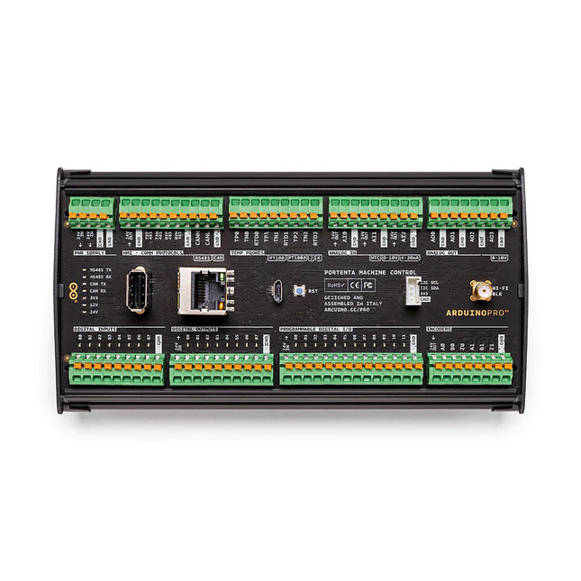
The Portenta Machine Control is a fully-centralized, low-power, industrial control unit able to drive equipment and machinery. It can be programmed using the Arduino framework or other embedded development platforms. Thanks to its computing power, the Portenta Machine Control enables a wide range of predictive maintenance and AI use cases. It enables the collection of real-time data from the factory floor and supports the remote control of equipment, even from the cloud, when desired. Features Shorter Time-To-Market Give new life to existing products Add connectivity for monitoring and control Tailor it to your need, each I/O pin can be configured Make equipment smarter to be ready for the AI revolution Provide security and robustness from the ground up Open new business model opportunity (e.g. servitization) Interact with your equipment with advanced HMI Modular Design for adaptation & upgrades The Portenta Machine Control allows companies to enable new business-as-a-service models by monitoring customer usage of equipment for predictive maintenance and providing valuable production data. The Portenta Machine Control enables industry standard soft-PLC control and is able to connect to a range of external sensors and actuators with isolated digital I/O, 4-20 mA compatible analog I/O, 3 configurable temperature channels, and a dedicated I²C connector. Multiple choices are available for network connectivity, including USB, Ethernet, and WiFi/Bluetooth Low Energy in addition to industry specific protocols such as RS485. All I/O are protected by resettable fuses and onboard power management has been engineered to ensure maximum reliability in harsh environments. The Portenta Machine Control core runs a Portenta H7 microcontroller board (included), a highly reliable design operating at industrial temperature ranges (-40 °C to +85 °C) with a dual-core architecture that doesn’t require any external cooling. The main processor offers the possibility of connecting external Human Machine Interfaces like displays, touch panels, keyboards, joysticks, and mice to enable on-site reconfiguration of state machines and direct manipulation of processes. The Portenta Machine Control’s design addresses a large variety of use scenarios. It is possible to configure a selection of the I/O pins via software. The Portenta Machine Control stands out as a powerful computer to unify and optimize production where one single type of hardware can serve all of your needs. Among other outstanding features are the following: Industrial performance leveraging the power of Portenta boards DIN bar compatible housing Push-in terminals for fast connection Compact device (170 x 90 x 50 mm) Reliable design, operating at industrial temperature rates (-40 °C to +85 °C) with a dual-core architecture that doesn’t require any external cooling Embedded RTC (Real Time Clock) to ensure perfect synchronization of processes Leverage the embedded connectivity without any external parts The Portenta Machine Control can be used in multiple industries, across a wide range of machine types, including: labelling machine, form & seal machine, cartoning machine, gluing machine, electric oven, industrial washer & dryers, mixers, etc. Add the Portenta Machine Control to your existing processes effortlessly and become the owner of your solutions in the market of machines. Specifications Processor STM32H747XI Dual Cortex-M7+M4 32-bit low power Arm MCU (Portenta H7) Input 8 digital 24 VDC 2 channels encoder readings 3 Analog for PT100/J/K temperature probes (3-wire cable with compensation) 3 Analog input (4-20 mA/ 0-10 V/NTC 10K) Output 8 digital 24 VDC up to 0.5 A (short circuit protection) 4 analog 0-10 V (up to 20 mA output per channel) Other I/O 12 programmable digital I/O (24 V logic) Commmunication protocols CAN-BUS Programmable Serial port 232/422/485 Connectivity Ethernet USB Programming Port Wi-Fi Bluetooth Low Energy Memory 16 MB onboard Flash memory 8 MB SD-RAM Dimensions 170 x 90 x 50 mm Weight 186 g Power 24 VDC +/- 20% Connector type Push-in terminals for fast connection Operating temperature -40 °C to +85 °C (-40 °F to 185 °F) Downloads Datasheet Schematics Pinout
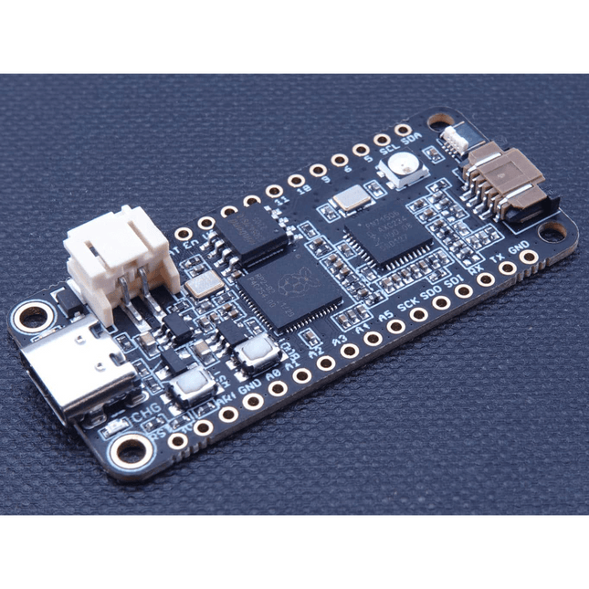
The Challenger RP2040 NFC is a small embedded computer, equipped with an advanced on-board NFC controller (NXP PN7150), in the popular Adafruit Feather form factor. It is based on an RP2040 microcontroller chip from the Raspberry Pi Foundation which is a dual-core Cortex-M0 that can run on a clock up to 133 MHz. NFC The PN7150 is a full featured NFC controller solution with integrated firmware and NCI interface designed for contactless communication at 13.56 MHz. It is fully compatible with NFC forum requirements and is greatly designed based on learnings from previous NXP NFC device generation. It is the ideal solution for rapidly integrating NFC technology in any application, especially small embedded systems reducing Bill of Material (BOM). The integrated design with full NFC forum compliancy gives the user all the following features: Embedded NFC firmware providing all NFC protocols as pre-integrated feature. Direct connection to the main host or microcontroller, by I²C-bus physical and NCI protocol. Ultra-low power consumption in polling loop mode. Highly efficient integrated power management unit (PMU) allowing direct supply from a battery. Specifications Microcontroller RP2040 from Raspberry Pi (133 MHz dual-core Cortex-M0) SPI One SPI channels configured I²C Two I²C channel configured (dedicated I²C for the PN7150) UART One UART channel configured Analog inputs 4 analog input channels NFC module PN7150 from NXP Flash memory 8 MB, 133 MHz SRAM memory 264 KB (divided into 6 banks) USB 2.0 controller Up to 12 MBit/s full speed (integrated USB 1.1 PHY) JST Battery connector 2.0 mm pitch On board LiPo charger 450 mA standard charge current Dimensions 51 x 23 x 3,2 mm Weight 9 g Note: Antenna is not included. Downloads Datasheet Quick start example
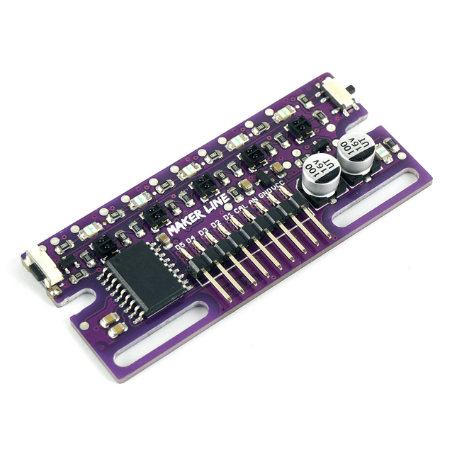
Maker Line is a line sensor with 5 x IR sensors array that is able to track line from 13 mm to 30 mm width. The sensor calibration is also simplified. There is no need to adjust the potentiometer for each IR sensor. You just have to press the calibrate button for 2 seconds to enter calibration mode. Afterwards you need to sweep the sensors array across the line, press the button again and you are good to go. The calibration data is saved in EEPROM and it will stay intact even if the sensor has been powered off. Thus, calibration only needs to be carried out once unless the sensor height, line color or background color has changed. Maker Line also supports dual outputs: 5 x digital outputs for the state of each sensor independently, which is similar to conventional IR sensor, but you get the benefit of easy calibration, and also one analog output, where its voltage represents the line position. Analog output also offers higher resolution compared to individual digital outputs. This is especially useful when high accuracy is required while building a line following robot with PID control. Features Operating Voltage: DC 3.3 V and 5 V compatible (with reverse polarity protection) Recommended Line Width: 13 mm to 30 mm Selectable line color (light or dark) Sensing Distance (Height): 4 mm to 40 mm (Vcc = 5 V, Black line on white surface) Sensor Refresh Rate: 200 Hz Easy calibration process Dual Output Types: 5 x digital outputs represent each IR sensor state, 1 x analog output represents line position. Support wide range of controllers such as Arduino, Raspberry Pi etc. Documentation Datasheet Tutorial: Building A Low-Cost Line Following Robot
Over 50 Circuits & Projects US-Style Siren Two Rotary Encoders on One Analog Input How to Build a Digital 220-V AC Dimmer with Arduino Current Source for LEDs Detect Four Switches with 1 Pin Tiny On/Off Switch with Battery Level Check DIY Hand Sanitizer Dispenser A Simple Electronic Organ Ultra-Simple Stereo Amplifier Sound Activated Switch for Amplifiers Balanced/Unbalanced Converter External Mains Filter Button-Free Door Control DI Box for a Smartphone Fun With Running Lights One-Button Thyristor Control Quasi-Analog Exposure Timer for the Dark Room Circuits Galore From the Hackster.io Community Analog Tanning Timer Yet Another Single-Wire LCD Interface Simple AVR ATtiny13-Based PWM Generator Second Life for Batteries Touch Switch for LED Lights Tester for LEDs and DIP Switches Go/No-Go IR Control Tester Power Semiconductor Tester SPI for WS2812(B) LEDs Measuring Power Inductors One Plug for Raspberry Pi and Audio DAC DIY Test Fixture for the LCR Meter Arduino Ammeter Two-Finger Organ Low Noise ADC Calibrator DC/DC Boost Converter Two Potentiometers on One Digital Input Acoustic Proximity Sensor Battery-Free Radiator Sensor A Circuit for Detecting Bugs and Wireless Cameras Car Interior Light Timer Candle Simulator Digital Kitchen Timer Milliohm Meter Hot Water Production Delay Timer Simple Charger for 2S 18650 Cells Tiny Frequency Reference Low-Power IR Switch Recycle Your Car’s Telephone Charger Microphone Pre-Amp for Arduino DIY EMI Filters Electronic Dice Without an MCU Finger Capacitor A Self-Charging LED Flasher Also in this edition KiCad 6 – Five Features to Consider Flashback – The Elektor SC/MP Computer Interview – Making Art with Electricity My First PCB – Going Head First Into KiCad Minimizing Hardware with Smart Software Infographics – Facts and Figures New Devices from Analog Flashback – The Elektor Metal Detector Hexadoku – The Original Elektorized Sudoku
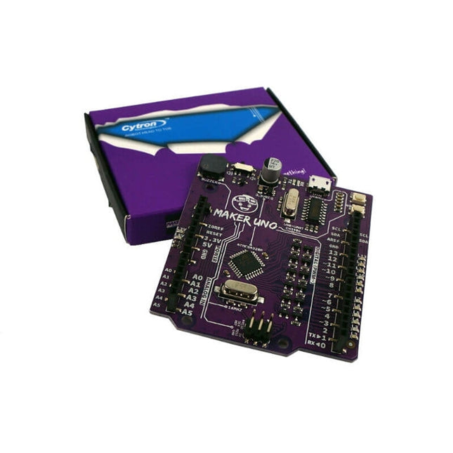
Features Piezo Buzzer: Acts as a simple audio output Micro USB Port Programmable Button 12 x LED: Provides visual output on board Specifications Microcontroller ATmega328P Programming IDE Arduino IDE Operating Voltage 5 V Digital I/O 20 PWM 6 Analog Input 6 (10-bit) UART 1 SPI 1 I2C 1 External Interrupt 2 Flash Memory 32 KB SRAM 2 KB EEPROM / Data Flash 1 KB Clock Speed 16 MHz DC Current I/O Pin 20 mA Power Supply USB only DC Current for 5 V USB Source DC Current for 3.3 V 500 mA USB to Serial Chip CH340G Programmable LED 12 at digital Pin 2 to 13 Programmable Push Button 1 at digital Pin 2 Piezo Buzzer 1 at digital Pin 8 Arduino vs Maker Uno
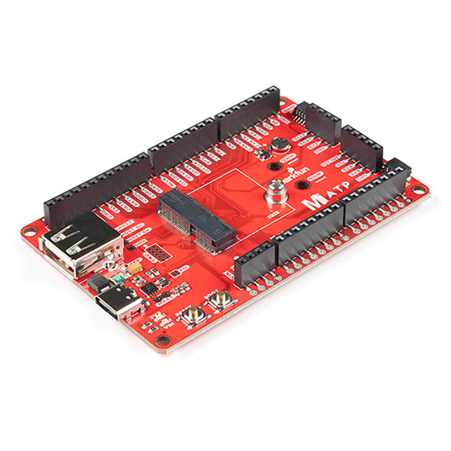
A modern USB-C connector makes programming easy. In addition to the pins broken out, two separate Qwiic-enabled I²C ports allow you to easily daisy chain Qwiic-enabled devices. We've exposed the SWD pins for more advanced users who prefer to use professional tools' power and speed. A USB-A connector is provided for Processor Boards that have USB Host support. A backup battery is provided for processor boards with RTC. If you need a 'lot' of GPIO with a simple-to-program, ready for the market module, the ATP is the fix you need. We've even added a convenient jumper to measure the current consumption for low power testing. Features M.2 Connector Operating Voltage Range ~3.3 V to 6.0 V (via VIN to AP7361C 3.3V Voltage Regulator) 3.3 V (via 3V3) Ports 1x USB type C 1x USB type A Host 2x Qwiic Enabled I²C 1x CAN 1x I²S 2x SPI 2x UARTs 2x Dedicated Analog Pins 2x Dedicated PWM Pins 2x Dedicated Digital Pins 12x General Purpose Input Output Pins 1x SWD 2x5 header 1 mAh battery backup for RTC Buttons Reset Boot LEDs Power 3.3 V Phillips #0 M2.5x3mm screw included
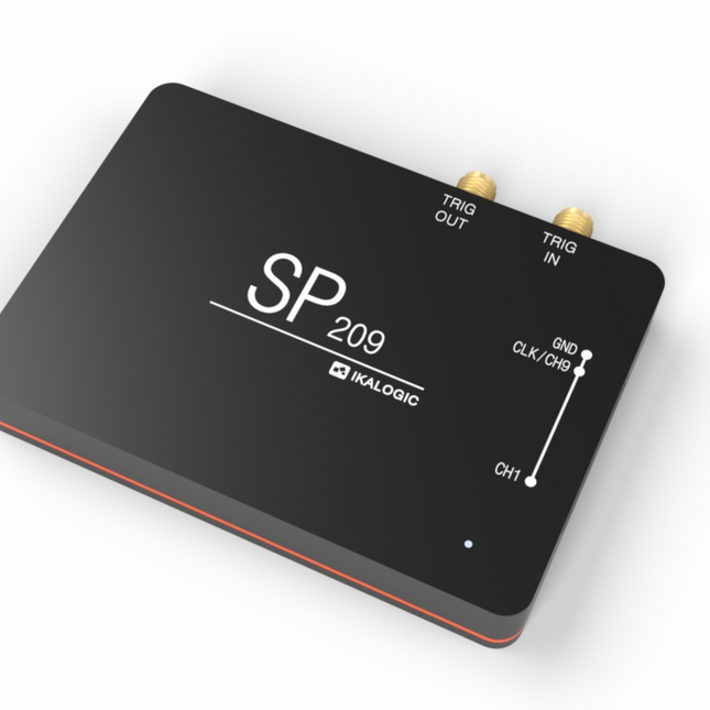
SP209 series logic analyzers rely on ScanaStudio software (runs Windows, Mac and Linux) to capture, display, analyze and decode signals. Most industry standard protocols can be interpreted, among which: SPI, I²C, USART, 1-Wire, CAN, LIN, IC, RS232, RS485, TWI and much more (click for full list of supported protocol decoders) Features 9 logic channels with adjustable thresholds (1.8 V, 2.5 V, 3.3 V, 5 V) State of the art input stage, with Schmitt triggers that eliminate glitches on slow signals 200 MHz sampling rate, with all 9 channels used. External clock option (state mode), up to 50 MHz Precise trigger-In and trigger-Out signals on SMA ports Samples compression and streaming via USB. 2 GB DDR-3 memory kicks-in when USB isn't fast enough. Guaranteed performances on all hosts. SP series logic analyzers compress and stream captured signals via USB 2.0 to a Windows, Linux or MacOS machine. USB bandwidth can be variable from a system to another and is practically limited to 20 MB/s. That's why SP logic analyzers have an embedded 2 GB DDR-3 memory that buffers captured samples at 1.6 GB/s, overcoming USB limitations. Trigger options Edge trigger Logic change on one or various channels Trigger on a sequence of timed logic signals Trigger on a protocol word or event (like serial word or I²C address acknowledge) External trigger input Trigger output Dual stage trigger (Ex: Edge trigger, then, Trigger on I²C address). Typical applications Designed for performance, SP series logic analyzers offer the possibility to capture and analyze 9 channels of logic signals and industrial buses at a rate of 200 MHz. This is perfectly adapted for demanding applications, where it is needed to capture logic signals with maximum resolution on all 9 channels. Embedded systems development and debugging Research and educational Serial protocols analysis, like I²C, SPI, UART or 1-Wire (non-exhaustive list) Industrial bus analysis: RS232, RS485, CAN, LIN ADC (Analog to Digital Converter) diagnostic Reverse engineering ScanaStudio application packs all the features you need to capture, measure and analyze analog signals. It's available free of charge for the major platforms below. The application is regularly updated, please check the release notes here ScanaStudio can be downloaded free of charge here. All decoders are free and open source and accessible in the GitHub repository.
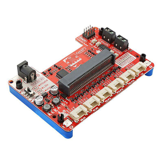
Program your REKA:BIT with Microsoft MakeCode Editor. Just add REKA:BIT MakeCode Extension and you’re good to go. If you’re a beginner, you can start with the block programming mode; simply drag, drop and snap the coding blocks together. For more advanced users, you can easily switch into JavaScript or Python mode on MakeCode Editor for text-based programming.REKA:BIT possesses a lot of indicator LEDs to assist your coding and troubleshooting. It covers the IO pins connected to all six Grove ports and DC motor outputs from the co-processor. One is able to check his/her program and circuit connection easily by monitoring these LEDs.Besides, REKA:BIT also has a power on/off indicator, undervoltage, and overvoltage LEDs built-in to give appropriate warnings should there be any problem with the power input.REKA:BIT features a co-processor to handle multitasking more efficiently. Playing music while controlling up to 4x servo motors and 2x DC motors, animating micro:bit LED matrix, and even lighting up RGB LEDs in different colors, all at the same time, is not a problem for REKA:BIT.Features
2x DC motor terminalsBuilt-in motor quick test buttons (no coding needed)
4x Servo motor ports
2x Neopixel RGB LEDs
6x Grove port (3.3 V)
3x Analog Input / Digital IO ports
2x Digital IO ports
1x I²C Interface
DC jack for power input (3.6 - 6 VDC)
ON/OFF switch
Power on indicator
Undervoltage (LOW) indicator & protection
Over-voltage (HIGH) indicator & protection
Dimensions: 10.4 x 72 x 15 mm
Included
1x REKA:BIT expansion board
1x USB power and data cable
1x 4xAA battery holder
1x Mini screwdriver
3x Grove to female header cable
2x Building block 1x9 lift arm
4x Building block friction pin
Please note: micro:bit board not included