Search results for "Platino-based Experimenter's Power Supply."
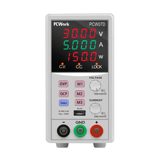
PCWork PCW07D Laboratory Switching Power Supply (DC 0-50 V, 0-6 A)
The PCW07D laboratory power supply is a high quality DC switching power supply designed specifically for laboratory applications. With an output voltage of 0-50 V and an output current of 0-6 A, it offers a maximum power of 150 W to handle even the most demanding tasks. Whether you are a student working on projects or a professional user who needs precise results, this power supply will meet your needs. Stable and accurate output for precise measurements and experiments The PCW07D laboratory power supply features stable and precise output. Thanks to innovative technology, it delivers a constant voltage or current regardless of load changes or fluctuating input voltages. This stability ensures accurate measurements and precise experiments. The power supply has high setting accuracy, so you can target your desired values. Intuitive operation and convenient functions The PCW07D laboratory power supply offers you intuitive operation and practical functions. The large, 4-digit LED display makes it easy to read the set values. The 3 memory buttons allow you to save your favorite settings and recall them at any time. The ability to set over-voltage and over-current protection functions provides additional safety. The innovative design of the laboratory power supply is not only visually impressive, but also offers practical advantages. The compact dimensions allow space-saving installation in the laboratory. The USB interface allows you to connect to other devices and the lock function provides additional protection against unauthorized operation. In addition, the power supply features short-circuit, overload, overheat and current-limit protection to keep your equipment and applications safe. Specifications Regulated output voltage 0-50 V Regulated output current 0-6 A (max output 150 W) Input voltage 104~127 V AC (60 Hz)207~253 V AC (50 Hz) Line regulation CV ≤0.1% +3 mV CC ≤0.2% +3 mA Load regulation CV ≤0.1% +3 mV CC ≤0.5% +10 mA Ripple and noise CV ≤5 mVr.m.s CC ≤20 mAr.m.s Protection Current limiting and short-circuit protection, over current protection, over voltage protection Voltage indication accuracy LED ±0.5% +5 digits Current indication accuracy LED ±0.5% +5 digits Environment 0~+40°C relative humidity <90%
€ 124,95€ 104,95
Members identical
Kitronik Kitronik Discovery Kit for Raspberry Pi Pico
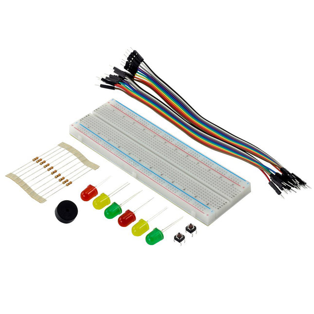
The kit ships with a comprehensive guide booklet. The booklet covers the basic setup and then how to complete each of the 7 experiments. Each experiment is complete with detailed circuit diagrams, explanations, and a complete code run-through. This means that you can get started without having to understand too much Python.The Raspberry Pi Pico board, a new low cost, high-performance microcontroller. The board features a powerful new, Raspberry Pi designed ARM-based dual-core chip-- the RP2040. The pico also features 64KB of internal RAM and support for up to 16MB of off-chip Flash. A wide range of flexible I/O options includes I2C, SPI, and Programmable I/O (PIO). These support endless possible applications for this small and affordable board.The kit is programmed using MicroPython. This is a full Python 3 implementation created specifically for small embedded microcontrollers, such as the Pico and the popular BBC micro:bit. You will use the Thonny editor to create your code, which can then be saved directly to the Pico from the editor via USB. Thonny is a Python Editor/IDE designed to allow beginners to get up and running with Python coding with as little fuss as possible.A power pack is not required as power will be supplied via the USB connection to the computer that the Thonny editor is running on.Features This kit offers a great introduction to microcontrollers, Python coding, and physical computing. Make the 7 experiments in the step-by-step tutorial book and learn as you go. All parts are included to conduct the 7 experiments. The kit is supplied with a detailed booklet that covers setup and then how to complete the 7 experiments. The experiments explore; simple coding, Interrupts, Threads, Digital Inputs, and Analog and Digital Outputs. Once you have completed all of the included experiments, you have the perfect prototyping system for further learning/prototyping with the Raspberry Pi Pico board. Included is a large format breadboard for ease of prototyping. The kit is supplied in re-usable packaging suitable for long term storage of the kit. Contents 1x Large Prototype Breadboard 2x Red 5mm LED 2x Yellow 5mm LED 2x Green 5mm LED 10x 330Ω Resistor 1x Piezo Element Buzzer 20x Male to Male Jumper Wires 2x Push Switches A booklet guide containing basic setup information and the following 7 experiments Exp. 1 - Show Me The Light Exp. 2 - Control an Input Exp. 3 - Interrupt Me Exp. 4 - Making a Noise Exp. 5 - So Many Interruptions Exp. 6 - Rub Head and Pat Tummy - Threads Exp. 7 - Building a System from the Blocks we have Learnt The kit is supplied in re-usable packaging suitable for long term storage of the kit. Requires USB Lead Raspberry Pi Pico Pin Headers
€ 17,95
Members € 16,16
Elektor Digital Mastering the I²C Bus (E-book)
Mastering the I²C Bus takes you on an exploratory journey of the I²C Bus and its applications. Besides the Bus protocol, plenty of attention is given to the practical applications and designing a stable system. The most common I²C compatible chip classes are covered in detail. Two experimentation boards are available that allow for rapid prototype development. These boards are completed by a USB to I²C probe and a software framework to control I²C devices from your computer. All samples programs can be downloaded from the 'Attachments/Downloads' section on this page. Projects built on Board 1: USB to I²C Interface, PCA 9534 Protected Input, PCA 9534 Protected Output, PCA 9553 PWM LED Controller, 24xxx EEPROM Module, LM75 Temperature Sensor, PCA8563 Real-time Clock with Battery Backup, LCD and Keyboard Module, Bus Power Supply. Projects built on Board 2: Protected Input, Protected Output, LM75 Temperature Sensor, PCF8574 I/O Board, SAA1064 LED Display, PCA9544 Bus Expander, MCP40D17 Potentiometer, PCF8591 AD/DA, ADC121 A/D Converter, MCP4725 D/A Converter, 24xxx EEPROM Module.
€ 29,95
Members € 23,96
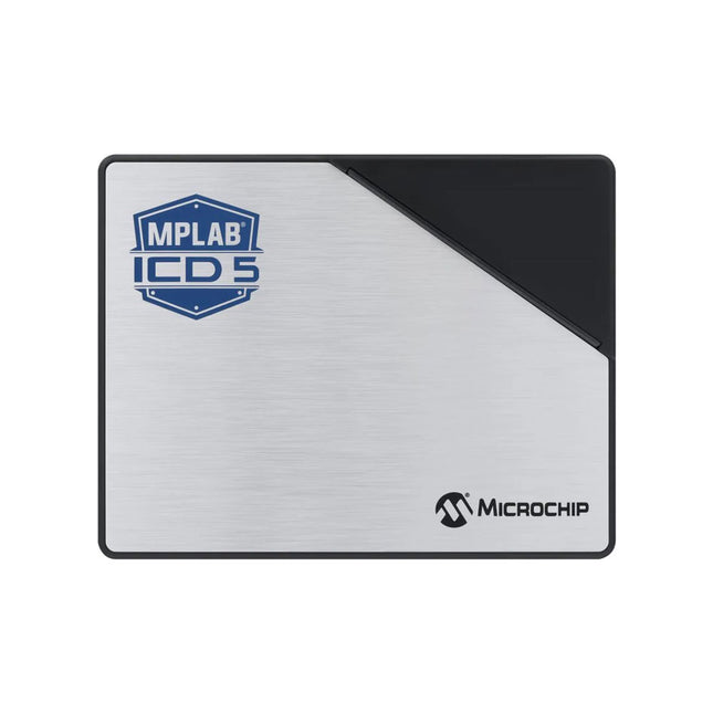
Microchip Microchip MPLAB ICD 5 in-circuit debugger/programmer
The MPLAB ICD 5 In-Circuit Debugger/Programmer offers advanced connectivity and power options for developers of designs based on PIC, AVR and SAM devices and dsPIC Digital Signal Controllers (DSCs). It debugs and programs with the powerful and easy-to-use graphical user interface of MPLAB X Integrated Development Environment (IDE). This next-generation tool offers a variety of capabilities and features that you would normally find in more expensive products to speed up your development and reduce your debug time. With its support for Fast Ethernet connectivity and Power over Ethernet Plus (PoE+), the MPLAB ICD 5 Debugger/Programmer offers flexibility and the convenience of remote development while isolating your application from environmental conditions. Whether you're an experienced developer or just starting out, the MPLAB ICD 5 In-Circuit Debugger/Programmer will accelerate your development process and help you take your designs to the next level. Features USB-C interface makes it easy to connect to a PC High-Speed USB 2.0 host PC interface supports speeds up to 480 Mbps for fast data transfer rates PoE+ (IEEE 802.3at) offers a convenient and flexible option to power up the debugger/programmer and deliver power to the target Fast Ethernet connectivity supports speeds up to 100 Mbps Wired/DHCP/APIAP IP addressing Static IP addressing Connects to more targets using an RJ11 or RJ45 modular cable Includes adapter board that supports JTAG, SWD, ICSP and AVR MCU protocols Professional-grade safety features and support for devices ranging from 1.2 V to 5.5 V Safely powers the target at up to 1 A using the PoE power supply or a PC with a USB-C connector Receives feedback from debugger when an external power supply is needed for the target CE and RoHS compliant, conforms to industry standards Advanced trace capabilities Support for instrumented trace via the Arm Serial Wire Debug (SWD) interface Power monitoring Allows you to optimize your design's power consumption Captures power data, such as current and voltage values Works with MPLAB Data Visualizer, which graphically analyzes power data Data gateway interfaces UART over Windows Virtual COM Port (VCP) Power Continuous Integration/Continuous Delivery (CI/CD) Support Can be implemented over Ethernet using hardware in the loop Works with CI/CD wizard available with MPLAB X IDE v6.10 and later to set up system using Jenkins and Docker Powerful debugging High-powered debugging with MPLAB X IDE Multiple breakpoints, stopwatch and source code file debugging Selectable pull-up/pull-down option to the target interface in MPLAB X IDE’s editor for quick program modification and debugging High-speed programming Quick firmware reloading for fast debugging and in-circuit reprogramming Debugging speed can be adjusted for optimized programming Included MPLAB ICD 5 In-Circuit Debugger and Programmer USB-C cable Adapter kit Downloads User guide Datasheet
€ 649,00
Members € 584,10
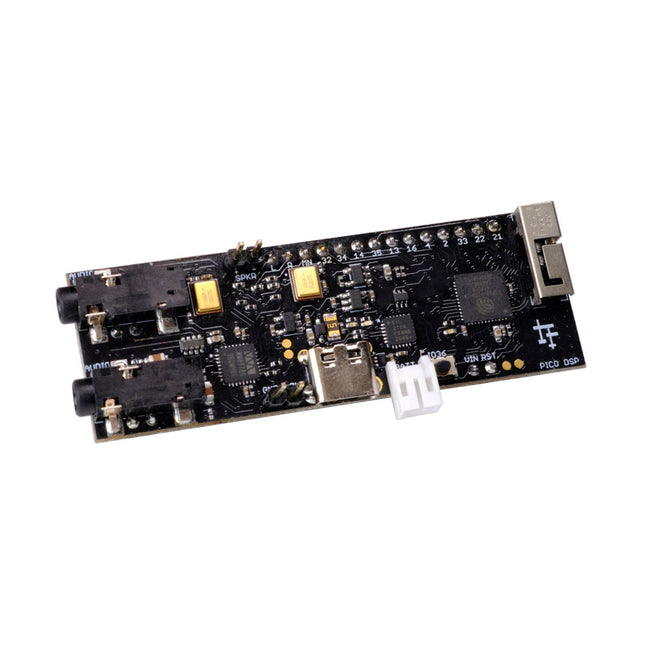
PÚCA DSP ESP32 Development Board
PÚCA DSP is an open-source, Arduino-compatible ESP32 development board for audio and digital signal processing (DSP) applications with expansive audio-processing features. It provides audio inputs, audio outputs, a low-noise microphone array, an integrated test-speaker option, additional memory, battery-charge management, and ESD protection all on a small, breadboard-friendly PCB. Synthesizers, Installations, Voice UI, and More PÚCA DSP can be used for a wide range of DSP applications, including but not limited to those in the fields of music, art, creative technology, and adaptive technology. Music-related examples include digital-music synthesis, mobile recording, Bluetooth speakers, wireless line-level directional microphones, and the design of smart musical instruments. Art-related examples include acoustic sensor networks, sound-art installations, and Internet-radio applications. Examples related to creative and adaptive technology include voice user interface (VUI) design and Web audio for the Internet of Sounds. Compact, Integrated Design PÚCA DSP was designed for portability. When used with an external 3.7 V rechargeable battery, it can be deployed almost anywhere or integrated into just about any device, instrument, or installation. Its design emerged from months of experimentation with various ESP32 development boards, DAC breakout boards, ADC breakout boards, Microphone breakout boards, and audio-connector breakout boards, and – despite its diminutive size – it manages to provide all of that functionality in a single board. And it dos so without compromising signal quality. Specifications Processor & Memory Espressif ESP32 Pico D4 Processor 32-bit dual core 80 MHz / 160 MHz / 240 MHz 4 MB SPI Flash with 8 MB additional PSRAM (Original Edition) Wireless 2.4 GHz Wi-Fi 802.11b/g/n Bluetooth BLE 4.2 3D Antenna Audio Wolfson WM8978 Stereo Audio Codec Audio Line In on 3.5 mm stereo onnector Audio Headphone / Line Out on 3.5 mm stereo connector Stereo Aux Line In, Audio Mono Out routed to GPIO Header 2x Knowles SPM0687LR5H-1 MEMS Microphones ESD protection on all audio inputs and outputs Support for 8, 11.025, 12, 16, 22.05, 24, 32, 44.1 and 48 kHz sample rates 1 W Speaker Driver, routed to GPIO Header DAC SNR 98 dB, THD -84 dB (‘A’ weighted @ 48 kHz) ADC SNR 95 dB, THD -84 dB (‘A’ weighted @ 48 kHz) Line input impedance: 1 MOhm Line output impedance: 33 Ohm Form Factor and Connectivity Breadboard friendly 70 x 24 mm 11x GPIO pins broken out to 2.54 mm pitch header, with access to both ESP32 ADC channels, JTAG and capacitive touch pins USB 2.0 over USB Type C connector Power 3.7/4.2 V Lithium Polymer Rechargeable Battery, USB or external 5 V DC power source ESP32 and Audio Codec can be placed into low power modes under software control Battery voltage level detection ESD protection on USB data bus Downloads GitHub Datasheet Links Crowd Supply Campaign (includes FAQs) Hardware Overview Programming the Board The Audio Codec
€ 69,95
Members € 62,96
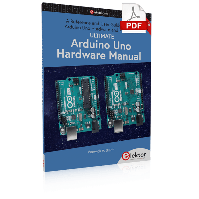
Elektor Digital Ultimate Arduino Uno Hardware Manual (E-book)
A Reference and User Guide for the Arduino Uno Hardware and Firmware A manual providing up-to-date hardware information for the popular Arduino Uno, the easy to use open-source electronics platform used by hobbyists, makers, hackers, experimenters, educators and professionals. Get all the information that you need on the hardware and firmware found on Arduino Uno boards in this handy reference and user guide. ldeal for the workbench or desktop Contains all of the Arduino Uno hardware information in one place Covers Arduino / Genuino Uno revision 3 and earlier boards Easily find hardware technical specifications with explanations Pin reference chapter with interfacing examples Diagrams and illustrations for easy reference to alternate pin functions and hardware connections Learn to back up and restore firmware on the board, or load new firmware Basic fault finding and repair procedures for Arduino Uno boards Power supply circuits simplified and explained Mechanical dimensions split into five easy to reference diagrams Contains circuit diagrams, parts list and board layout reference to easily locate components
€ 24,95
Members € 19,96
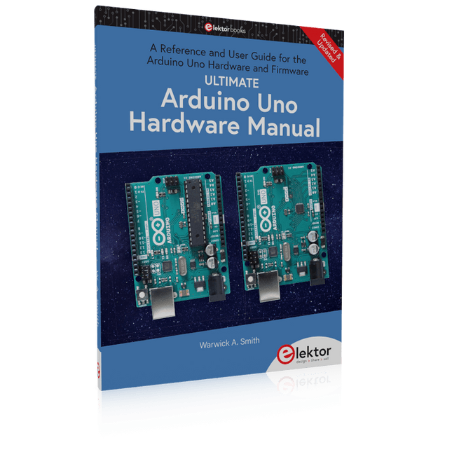
Ultimate Arduino Uno Hardware Manual
A Reference and User Guide for the Arduino Uno Hardware and Firmware A manual providing up-to-date hardware information for the popular Arduino Uno, the easy to use open-source electronics platform used by hobbyists, makers, hackers, experimenters, educators and professionals. Get all the information you need on the hardware and firmware found on Arduino Uno boards in this handy reference and user guide. Ideal for the workbench or desktop Contains all of the Arduino Uno hardware information in one place Covers Arduino / Genuino Uno revision 3 and earlier boards Easily find hardware technical specifications with explanations Pin reference chapter with interfacing examples Diagrams and illustrations for easy reference to alternate pin functions and hardware connections Learn to back up and restore the firmware on the board or load new firmware Basic fault finding and repair procedures for Arduino Uno boards Power supply circuits simplified and explained Mechanical dimensions split into five easy to reference diagrams Contains circuit diagrams, parts list and board layout reference to locate components easily
€ 29,95
Members € 26,96
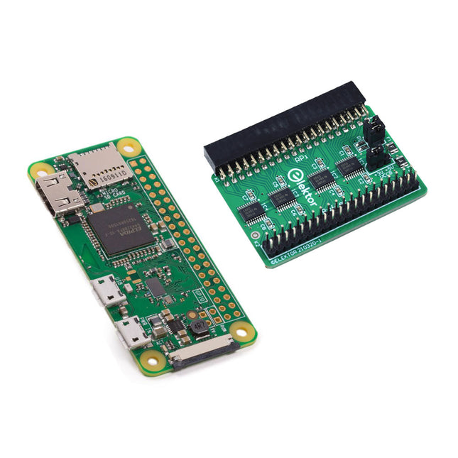
Elektor Bundles Raspberry Pi Bundle: Zero W + Buffer Board (+ FREE Special)
The Raspberry Pi and Pico Special (worth €15) will automatically be added to your cart! This bundle includes the Raspberry Pi Zero W and the Elektor Raspberry Pi Buffer Board. Raspberry Pi Zero W The Raspberry Pi Zero W is the newest member of the Raspberry Pi Zero family. The Raspberry Pi Zero W has all the functionality of the original Raspberry Pi Zero, but comes with added connectivity consisting of: 802.11 b/g/n WLAN Bluetooth 4.1 Bluetooth Low Energy (BLE) Other features 1 GHz, single-core CPU 512 MB RAM Mini HDMI and USB On-The-Go ports Micro-USB power supply HAT-compatible 40-pin header Composite video and reset headers CSI camera connector Downloads Mechanische tekening Schema's Elektor Raspberry Pi Buffer Board When you experiment with the Raspberry Pi on a regular basis and you connect a variety of external hardware to the GPIO port via the header you may well have caused some damage in the past. The Raspberry Pi Buffer Board is there to prevent this! The board is compatible with Raspberry Pi Zero, 3, 4, 5 and 400. All 26 GPIOs are buffered with bi-directional voltage translators to protect the Raspberry Pi when experimenting with new circuits. The PCB is intended to be inserted in the back of Raspberry Pi< 400. The connector to connect to the Raspberry Pi is a right angled 40-way receptacle (2x20). The PCB is only a fraction wider. A 40-way flat cable with appropriate 2x20 headers can be connected to the buffer output header to experiment for instance with a circuit on a breadboard or PCB. The circuit uses four TXS0108E ICs by Texas Instruments. The PCB can also be put upright on a Raspberry Pi 3 or newer. Downloads Schematics Layout
€ 64,95€ 49,95
Members identical


-
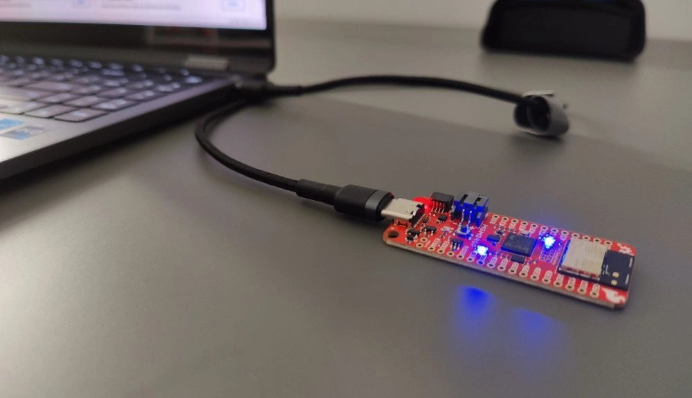
, by Saad Imtiaz SparkFun Thing Plus Matter (MGM240P): A Versatile Matter-Based IoT Development Board (Review)
The SparkFun Thing Plus Matter (MGM240P) is a versatile and feature-rich development board designed for creating Matter-based IoT devices. Matter, formerly known as Project CHIP...
-
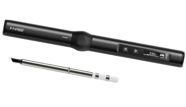
, by Jean-François Simon Fnirsi HS-01 Smart Soldering Iron (Review)
Get to know the Fnirsi HS-01, a soldering iron designed for versatility. The adjustable soldering iron features a built-in 0.87-inch OLED display that quickly reaches...
-
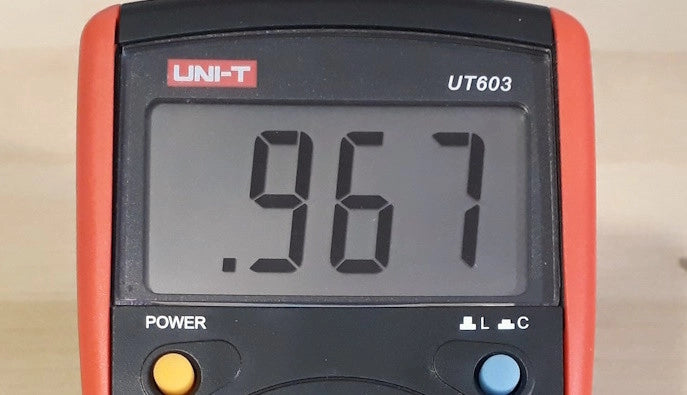
, by Jean-François Simon LCR Meter: The UNI-T UT603 (Review)
Looking for a portable LCR meter? Check out the features and uses for the UNI-T UT603 LCR meter in our detailed review!
-
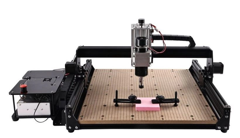
, by Clemens Valens The Anet 4540 Desktop CNC and Engraving Machine
Like 3D printers and laser engraving machines, CNC machines have become more mainstream too. Where they used to cost thousands of euros in the past,...


