There are many so-called 'Arduino compatible' platforms on the market. The ESP8266 – in the form of the WeMos D1 Mini Pro – is one that really stands out. This device includes WiFi Internet access and the option of a flash file system using up to 16 MB of external flash memory. Furthermore, there are ample in/output pins (though only one analogue input), PWM, I²C, and one-wire. Needless to say, you are easily able to construct many small IoT devices!
This book contains the following builds:
A colourful smart home accessory
refrigerator controller
230 V power monitor
door lock monitor
and some further spin-off devices.
All builds are documented together with relevant background information for further study. For your convenience, there is a small PCB for most of the designs; you can also use a perf board. You don’t need to be an expert but the minimum recommended essentials include basic experience with a PC, software, and hardware, including the ability to surf the Internet and assemble PCBs.
And of course: A handle was kept on development costs. All custom software for the IoT devices and PCB layouts are available for free download from at Elektor.com.
Affordable solutions with the ESP8266 and 3D printing
If you are looking for a small yet powerful IoT device, you are likely to come across the ESP8266 and compatible products on the market today. One of these, the Wemos/Lolin D1 Mini Pro board strikes a remarkable balance between cost and performance. A small and very affordable prototype board, the D1 Mini Pro stands out with its WiFi functionality and a 16-Mbytes flash memory for easy creation of a flash file system. In addition, there are sufficient input and output pins (only one analog input though) to support PWM, I²C, and One-Wire systems to mention but a few. The book describes the operation, modding, construction, and programming of home appliances including a colorful smart home accessory, a refrigerator/greenhouse controller, an AC powerline monitor, a door lock monitor, and an IKEA Trådfri controller.
As a benefit, all firmware developed for these DIY, "IoT-ized" devices can be updated over-the-air (OTA).
For most of the designs in the book, a small printed circuit board (PCB) and an enclosure are presented so readers can have a finished and attractive-looking product. Readers having – or with access to! – a 3D printer can "print" the suggested enclosures at home or in a shop.
Some of the constructions benefit from a Raspberry Pi configured as a gateway or cms server. This is also described in detail with all the necessary configuring.
You don’t need to be an expert but the prerequisites to successful replication of the projects include basic skills with PC software including the ability to surf the Internet. In terms of hardware, you should be comfortable with soldering and generally assembling the PCBs presented in the book.
All custom software written for the IoT devices, the PCB layouts, and 3D print files described in the book are available for free downloading.
In 35 Projects with the Raspberry Pi and Arduino
The Internet of Things (IoT) is a trend with a strong technological impulse. At home, we want to do everything on our tablets, from browsing Facebook to watching TV, from operating lights to keeping an eye on the temperature.
In 35 fun projects, this book will show you how to build your own Internet of Things system. We'll cover the hardware (primarily the Raspberry Pi and Arduino) and the software that makes control via Internet possible. We employ Wi-Fi and radio links so no requirement any longer to install cabling crisscross through your home.
Assuming the projects in the book are finished, you have a complete Internet of Things system that allows you to control and view of everything in your home. For example, if there's something in the mail box or the car is securely in the garage. Also, you can switch on the lights and the alarm from your couch. The crisp explanations allow the projects to be customized with ease, for example, to turn on your coffee machine or TV remotely. The index gives easy access to creative projects that can serve as an example, enabling you to do all the connecting to the IoT independently. All project software can be downloaded free of charge from the Elektor website.
In this unique book, Raspberry Pi, Arduino and HTML webpages with stylesheets and JavaScript come together in clearly-described, easy-to-build projects. This special book is an essential part of your collection!
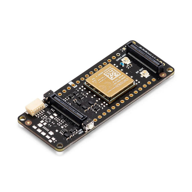
The Arduino Pro Portenta Cat. M1/NB IoT GNSS Shield allows you to enhance the connectivity features of your Portenta H7 applications. The shield leverages a Cinterion TX62 wireless module by Thales, designed for highly efficient, low-power IoT applications to deliver optimized bandwidth and performance.
The Portenta Cat. M1/NB IoT GNSS Shield combines with the strong edge computing power of the Portenta H7 to enable the development of asset tracking and remote monitoring applications in industrial settings, as well as in agriculture, public utilities and smart cities. The shield offers cellular connectivity to both Cat. M1 and NB-IoT networks with the option to use eSIM technology. Easily track your valuables – across the city or worldwide – with your choice of GPS, GLONASS, Galileo or BeiDou.
Features
Change connectivity capabilities without changing the board
Add NB-IoT, CAT. M1 and positioning to any Portenta product
Possibility to create a small multiprotocol router (WiFi - BT + NB-IoT/CAT. M1)
Greatly reduce communication bandwidth requirements in IoT applications
Low-power module
Compatible also with MKR boards
Remote Monitoring
Industrial and agricultural companies can leverage the Portenta Cat. M1/NB IoT GNSS Shield to remotely monitor gas detectors, optical sensors, machinery alarm systems, biological bug traps and more.
Technology providers providing smart city solutions can compound the power and reliability of the Portenta H7 with the Portenta Cat. M1/NB IoT GNSS Shield, to connect data and automate actions for a truly optimized use of resources and enhanced user experience.
Asset Monitoring
Add monitoring capabilities to any asset by combining the performance and edge computing features of the Portenta family boards. The Portenta Cat. M1/NB IoT GNSS Shield is ideal to monitor valuable goods and also for monitoring industrial machinery and equipment.
Specifications
Connectivity
Cinterion TX62 wireless module; NB-IoT - LTE CAT.M1; 3GPP Rel.14 Compliant Protocol LTE Cat. M1/NB1/NB2; UMTS BANDS: 1 / 2 / 3 / 4 / 5 / 8 / 12(17) / 13 / 18 / 19 / 20 / 25 / 26 / 27 / 28 / 66 / 71 / 85; LTE Cat.M1 DL: max. 300 kbps, UL: max. 1.1 Mbps; LTE Cat.NB1 DL: max. 27 kbps, UL: max. 63 kbps; LTE Cat.NB2 DL: max. 124 kbps, UL: max. 158 kbps
Short messaging service (SMS)
Point-to-point mobile terminated (MT) and mobile originated (MO) Text Mode; Protocol Data Unit (PDU) Mode
Localization support
GNSS capability (GPS/BeiDou/Galileo/GLONASS)
Other
Embedded IPv4 and IPv6 TCP/IP stack access; Internet Services: TCP server/client, UDP client, DNS, Ping, HTTP client, FTP client, MQTT client Secure Connection with TLS/DTLS Secure boot
Dimensions
66 x 25.4 mm
Operating temperature
-40° C to +85° C (-104° F to 185°F)
Downloads
Datasheet
Schematics
Learn programming for Alexa devices, extend it to smart home devices and control the Raspberry Pi
The book is split into two parts: the first part covers creating Alexa skills and the second part, designing Internet of Things and Smart Home devices using a Raspberry Pi.
The first chapters describe the process of Alexa communication, opening an Amazon account and creating a skill for free. The operation of an Alexa skill and terminology such as utterances, intents, slots, and conversations are explained. Debugging your code, saving user data between sessions, S3 data storage and Dynamo DB database are discussed.
In-skill purchasing, enabling users to buy items for your skill as well as certification and publication is outlined. Creating skills using AWS Lambda and ASK CLI is covered, along with the Visual Studio code editor and local debugging. Also covered is the process of designing skills for visual displays and interactive touch designs using Alexa Presentation Language.
The second half of the book starts by creating a Raspberry Pi IoT 'thing' to control a robot from your Alexa device. This covers security issues and methods of sending and receiving MQTT messages between an Alexa device and the Raspberry Pi.
Creating a smart home device is described including forming a security profile, linking with Amazon, and writing a Lambda function that gets triggered by an Alexa skill. Device discovery and on/off control is demonstrated.
Next, readers discover how to control a smart home Raspberry Pi display from an Alexa skill using Simple Queue Service (SQS) messaging to switch the display on and off or change the color.
A node-RED design is discussed from the basic user interface right up to configuring MQTT nodes. MQTT messages sent from a user are displayed on a Raspberry Pi.
A chapter discusses sending a proactive notification such as a weather alert from a Raspberry Pi to an Alexa device. The book concludes by explaining how to create Raspberry Pi as a stand-alone Alexa device.
Ready-to-use devices and self-built Arduino nodes in the 'The Things Network'
LoRaWAN has developed excellently as a communication solution in the IoT. The Things Network (TTN) has contributed to this. The Things Network was upgraded to The Things Stack Community Edition (TTS (CE)). The TTN V2 clusters were closed towards the end of 2021.
This book shows you the necessary steps to operate LoRaWAN nodes using TTS (CE) and maybe extend the network of gateways with an own gateway. Meanwhile, there are even LoRaWAN gateways suitable for mobile use with which you can connect to the TTN server via your cell phone.
The author presents several commercial LoRaWAN nodes and new, low-cost and battery-powered hardware for building autonomous LoRaWAN nodes. Registering LoRaWAN nodes and gateways in the TTS (CE), providing the collected data via MQTT and visualization via Node-RED, Cayenne, Thingspeak, and Datacake enable complex IoT projects and completely new applications at very low cost.
This book will enable you to provide and visualize data collected with battery-powered sensors (LoRaWAN nodes) wirelessly on the Internet. You will learn the basics for smart city and IoT applications that enable, for example, the measurement of air quality, water levels, snow depths, the determination of free parking spaces (smart parking), and the intelligent control of street lighting (smart lighting), among others.
Learn programming for Alexa devices, extend it to smart home devices and control the Raspberry Pi
The book is split into two parts: the first part covers creating Alexa skills and the second part, designing Internet of Things and Smart Home devices using a Raspberry Pi.
The first chapters describe the process of Alexa communication, opening an Amazon account and creating a skill for free. The operation of an Alexa skill and terminology such as utterances, intents, slots, and conversations are explained. Debugging your code, saving user data between sessions, S3 data storage and Dynamo DB database are discussed.
In-skill purchasing, enabling users to buy items for your skill as well as certification and publication is outlined. Creating skills using AWS Lambda and ASK CLI is covered, along with the Visual Studio code editor and local debugging. Also covered is the process of designing skills for visual displays and interactive touch designs using Alexa Presentation Language.
The second half of the book starts by creating a Raspberry Pi IoT 'thing' to control a robot from your Alexa device. This covers security issues and methods of sending and receiving MQTT messages between an Alexa device and the Raspberry Pi.
Creating a smart home device is described including forming a security profile, linking with Amazon, and writing a Lambda function that gets triggered by an Alexa skill. Device discovery and on/off control is demonstrated.
Next, readers discover how to control a smart home Raspberry Pi display from an Alexa skill using Simple Queue Service (SQS) messaging to switch the display on and off or change the color.
A node-RED design is discussed from the basic user interface right up to configuring MQTT nodes. MQTT messages sent from a user are displayed on a Raspberry Pi.
A chapter discusses sending a proactive notification such as a weather alert from a Raspberry Pi to an Alexa device. The book concludes by explaining how to create Raspberry Pi as a stand-alone Alexa device.
This bundle includes the Red Pitaya STEMlab 125-14 PRO Gen 2 Starter Kit and the new book "Experimenting with Red Pitaya STEMlab Gen 2".
The Red Pitaya STEMlab 125-14 PRO Gen 2 Starter Kit is a powerful and flexible platform for signal processing, data acquisition, and electronic measurement applications. Designed for engineers, developers, researchers, and educators, this kit provides everything required to start building advanced measurement and control systems.
At the core of the kit is the STEMlab 125-14 PRO Gen 2 board, an upgraded and ultra-lightweight development platform. Powered by the Xilinx Zynq-7010 SoC with 512 MB of RAM, it combines FPGA programmability with ARM processing power to enable high-performance instrumentation and custom signal-processing solutions.
The board offers 14-bit ADC and DAC resolution, a 125 MS/s sampling rate, an input range of ±20 V, and up to 60 MHz bandwidth. Its improved low-noise analog front-end, USB-C connectivity, and compact design make it suitable for demanding applications such as RF development, radar systems, photonics research, software-defined radio (SDR), and industrial automation.
The Starter Kit includes all essential accessories for immediate use: a microSD card with preinstalled operating system, power supply, Ethernet cable for remote access, two 100 MHz oscilloscope probes, and SMA-to-BNC adapters for flexible signal connections.
The Red Pitaya STEMlab 125-14 PRO Gen 2 Starter Kit is an excellent platform for rapid prototyping, FPGA development, measurement instrumentation, and advanced electronics experimentation.
Features
14-bit ADC and DAC resolution
125 MS/s sampling rate
±20 V input range
Up to 60 MHz bandwidth
Xilinx Zynq-7010 SoC (FPGA + ARM processor)
512 MB RAM
Low-noise analog front- and back-ends
Applications
RF development and testing
Radar and wireless systems
Software-defined radio (SDR)
Photonics and optical research
Industrial automation and control systems
Signal analysis and instrumentation
Rapid prototyping of electronic measurement systems
Specifications
Processor
Dual-core ARM Cortex-A9
FPGA
AMD Xilinx Zynq-7010 SoC
RAM
512 MB (4 Gb)
Storage
microSD card (up to 32 GB)
Operating System
Linux-based Red Pitaya OS
ADC Resolution
14-bit
DAC Resolution
14-bit
Bandwidth
60 MHz (DC)
Sampling Rate
125 MS/s
Analog Input Channels
2
Analog Output Channels
2
Input Voltage Range
±1 V (LV) / ±20 V (HV)
Input Impedance
1 MΩ / 10 pF
Output Voltage Range
±1 V
Ethernet
1x Gigabit Ethernet (RJ45)
USB
2x USB-C 2.0 (for power and console)
Digital I/O
16x GPIO (3.3 V)
Communication Interfaces
I²C, SPI, UART, CAN
Power Supply
5 V/3 A via USB-C
Dimensions
106.8 x 60.0 x 17.9 mm
Included
1x Red Pitaya STEMlab 125-14 PRO Gen 2 board
2x 100 MHz oscilloscope probes
2x SMA-to-BNC adapters
1x microSD card with preinstalled OS
1x USB-C Power supply
1x Ethernet cable
Downloads
Documentation
Schematics
Book: Experimenting with Red Pitaya STEMlab Gen 2
With this new book, Red Pitaya goes beyond a versatile board. It becomes a powerful laboratory instrument for precision measurement, analysis, and control.
From the fundamentals of electronic project development, monitoring, control, and design to testing, this book walks you step-by-step through everything you need to know to harness the full potential of Red Pitaya hardware and software.
The book presents real-time, FPGA-based projects that are developed on a PC using the Vivado environment, then transferred to the Red Pitaya for execution and testing.
You will learn about enhanced performance, expanded I/O capabilities, improved FPGA features, and advanced connectivity options that open up new frontiers for precision measurement, monitoring, and control in your embedded applications.
Inside the book you will discover:
A deep dive into Red Pitaya architecture and hardware design
Electronic experiments using Red Pitaya for measurement and monitoring
Hands-on projects using the Python programming language
Practical guidance for FPGA programming using Red Pitaya
Red Pitaya FPGA projects using the Verilog HDL under Vivado IDE
Practical design of electronic projects including measurement and testing
Step-by-step examples that bridge theory and real-world implementation
Whether you are designing your own electronic circuits, developing signal analysis tools, or creating real-time control or monitoring systems, this book provides you the knowledge and confidence you need to fully learn and customize the Red Pitaya platform.
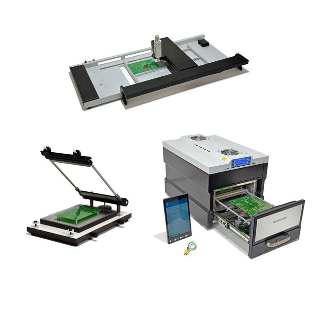
The SMD Starter I prototype production line consists of the stencil printer TSD240, the SMD placement device PlaceMAN and the reflow oven 3LHR10. Stencil printer SD240 (+ Metal Squeegee 155 mm) Stencil size: max. 175 x 255 mm PCB size: max. 180 x 240 mm Size: 410 x 270 x 110 mm Weight: 6.7 kg incl. metal squeegee 155 mm incl. 8 magnets to hold the PCB, 6 of them with M3 grub screw Manual SMD pick-and-place device PlaceMAN for standard components incl. vacuum pump (without feeders, camera, monitor and dispenser) Equipped with smooth-running placement arm, placement head with one-hand operation, rotation of the Z-axis and automatic vacuum switch-off, incl. PCB holder, vacuum unit and 2 placement needles with rubber suction cups. Capacity of feeder (not included) 2x feeder cassette for 10 x 8 mm wheels left 4x feeder cassette for rod feeders for 5 rods each Further feeding systems are possible within the assembly area, e.g. strip-feeder plug-in system Dimensions Base unit (LxWxH): 765 x 390 x 210 mm With feeder cassette for 10 x 8 mm rolls (LxWxH): 765 x 390 x 210 mm With feeder cassette for 10 x 8 mm rolls and feeder cassette for rod feeder (LxWxH): 765 x 430 x 210 mm (height may vary due to rod length) With feeder cassette for 10 x 8 mm rolls incl. holder for 10 rolls and feeder cassette for rod feeder (LxWxH): 765 x 430 x 210 mm (height may vary due to rod length) Specifications Weight of basic unit: approx. 6 kg Axis travel (x,y,z): 470 x 230 x 15 mm Max. working area: 380 x 240 mm Max. PCB size: 230 x 360 mm Power supply: 230/12 V, 800 mA Power supply vacuum pump: 230 V, 6 W 3LHR10 Reflow Oven (programmable for lead-free soldering with manual drawer and tablet control) Reflow oven with IR and convection heating. Forced hot air convection ensures a uniform temperature profile throughout the chamber. After manually opening the door, the fans are turned on and the soldered PCB is quickly cooled. Small reflow oven with manual door Industry 4.0 ready, Bluetooth communication + tablet IR + convection heating Android application to connect to tablet or smartphone 100 different user programs Delivery content: 3LHR10, tablet with app, protective cover for tablet, 4 PCB holders, external thermocouple, manual at tablet Application Connect the oven to the power supply and connect the optionally available extraction system (3LFE10S) to the exhaust air nozzle. After the first turn on, the oven will search for a tablet or smartphone. When both are connected to the Android app, choose the programming of the oven. Here, programmable temperature and preheating time as well as temperature and other data are to be set. Register with the tablet to use the full scope of the software. If the oven is already programmed, the user can control the operation with buttons and display at the front panel. When the reflow process is complete, an audible signal sounds. A signal is also displayed on the tablet/smartphone. The drawer must now be opened manually. The Android application displays process status, time and temperature or other information. Specifications Power supply: 230 V, 50 Hz Maximum power: 3100 W Temperatures: 50-260°C Dimensions: 510 x 370 x 340 mm Maximum weight: 16 kg Grid dimensions: 350 x 220 mm Maximum dimensions of the printed circuit board: 300 x 200 mm Maximum component height on the PCB: 50 mm at the top, 30 mm at the bottom Scope of delivery Stencil printer TSD240 SMD placement device PlaceMAN Reflow oven 3LHR10
,
by Saad Imtiaz
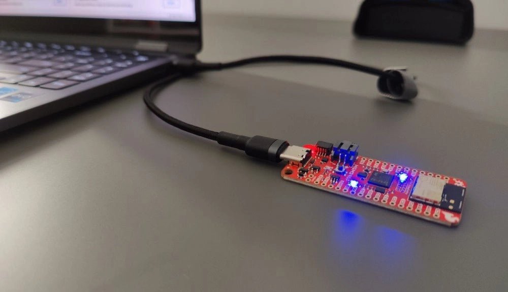
SparkFun Thing Plus Matter (MGM240P): A Versatile Matter-Based IoT Development Board (Review)
The SparkFun Thing Plus Matter (MGM240P) is a versatile and feature-rich development board designed for creating Matter-based IoT devices. Matter, formerly known as Project CHIP...