
Search results for "upgrade OR professionallicence OR flowcodev6 OR to OR v7"
-
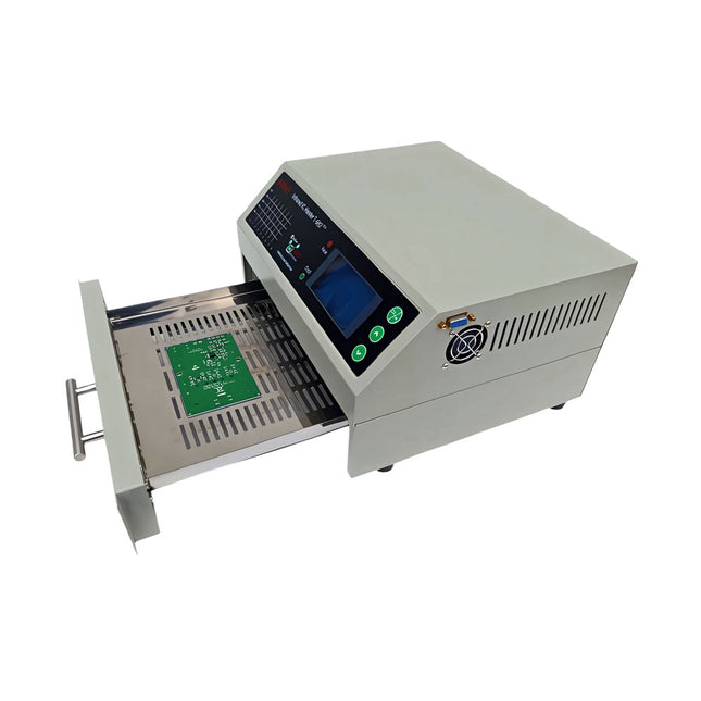
puhui Upgraded T-962 v2.0 Reflow Soldering Oven (Elektor Version)
This upgraded version 2.0 (available exclusively from Elektor) contains the following improvements: Enhanced protective earthing (PE) for furnace chassis Extra thermal insulation layer around furnace to reduce odors Connection to a computer, allowing curve editing on a PC Features such as constant temperature control and timing functions The infrared IC heater T-962 v2.0 is a microprocessor-controlled reflow oven that you can use for effectively soldering various SMD and BGA components. The whole soldering process can be completed automatically and it is very easy to use. This machine uses a powerful infrared emission and circulation of the hot air flow, so the temperature is being kept very accurate and evenly distributed. A windowed drawer is designed to hold the work-piece, and allows safe soldering techniques and the manipulation of SMDBGA and other small electronic parts mounted on a PCB assembly. The T-962 v2.0 may be used to automatically rework solder to correct bad solder joints, remove/replace bad components and complete small engineering models or prototypes. Features Large infrared soldering area Effective soldering area: 180 x 235 mm; this increases the usage range of this machine drastically and makes it an economical investment. Choice of different soldering cycles Parameters of eight soldering cycles are pre defined and the entire soldering process can completed automatically from Preheat, Soak and Reflow through to cool down. Special heat up and temperature equalization with all designs Uses up to 800 Watts of energy efficient Infrared heating and air circulation to re-flow solder. Ergonomic design, practical and easily operated Good build quality but at the same time light weight and a small footprint allows the T-962 v2.0 to be easily bench positioned transported or stored. Large number of available functions The T-962 v2.0 can solder most small parts of PCB boards, for example CHIP, SOP, PLCC, QFP, BGA etc. It is the ideal rework solution from single runs to on-demand small batch production. Specifications Soldering area (max) 180 x 235 mm (7.1 x 9.3") Power (max) 800 W Temperature range 0-280°C (32-536°F) Heating method Infrared Processing time 1~8 minutes Power supply 220 V AC/50 Hz Display LCD with Backlight Control mode 8 intelligent temperature curves Dimensions 310 x 290 x 170 mm (12.2 x 11.4 x 6.7") Weight 6.2 kg Included 1x T-962 v2.0 Reflow Soldering Oven (Elektor Version) 2x Fuses 1x Power cord (EU)
€ 349,00€ 299,00Best Price
-
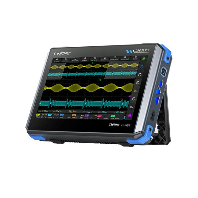
FNIRSI FNIRSI DPOS350P (4-in-1) 2-ch Tablet Oscilloscope (350 MHz) + Signal Generator + Frequency Response Analyzer + Spectrum Analyzer
2 Channels • 350 MHz • 1 GSa/s • 50,000 wfm/s • 7 inch Touchscreen The FNIRSI DPOS350P is a sleek 4-in-1 powerhouse in tablet form! This compact and portable device packs serious functionality: it combines a 2-channel oscilloscope (350 MHz), a signal generator (50 MHz), a frequency response analyzer (50 MHz), and a spectrum analyzer (200 kHz–350 MHz) – all in one unit. Whether you're in R&D, troubleshooting, or field testing, the DPOS350P delivers the tools you need to measure, generate, analyze, and visualize electronic signals with precision and clarity. Its responsive high-resolution touchscreen and intuitive controls make signal analysis fast, flexible and efficient. Features Powerful Multi-Function Integration 350 MHz 2-channel oscilloscope with 1 GSa/s real-time sampling 50 MHz signal generator with 14 standard + custom waveforms Spectrum analyzer (200 kHz–350 MHz): Perfect for EMI, RF & HF testing Frequency response analyzer (FRA) up to 50 MHz High-Performance Waveform Capture 50,000 wfm/s refresh rate for real-time signal clarity 350 MHz bandwidth (single-channel mode) Detects rare and low-probability anomalies Crisp Display & Smooth Operation 7" IPS touchscreen (1024 x 600 resolution) Switch between grayscale and color temperature display Easy to operate in various test environments Reliable, Protected & Fast-Charging High-voltage protection up to 400 V Fast charging with QC 18 W (full charge in 2 hours) Built for stable long-term operation Data Storage & Export Save up to 500 waveform records + 90 screenshots USB export for easy reporting and offline analysis Specifications General Display 7 inch (IPS full viewing angle) Resolution 1024 x 600 pixels Interaction mode Capacitive touch screen Total power consumption 10 W Power-on configuration 5 presets Charging QC 18 W, 12 V/1.5 A (USB-C) Battery 3.7 V, 8000 mAh lithium battery Battery life approx. 3 hours in operation, 5 hours standby Heat dissipation Air cooling Expansion interface USB data port Automatic shutdown 15~60 minutes / off Firmware upgrade Support .iso image upgrade Languages English / Portuguese / Russian / Chinese Dimensions 190 x 128 x 37 mm Oscilloscope Analog channels 2 Analog bandwidth 350 MHz Rise time 1ns Real-time sampling rate 1 GSa/s Memory depth 60 Kpts Input impedance 1 MΩ / 14PF Time base range 5ns ~ 50s Roll time base 50ms ~ 50s Vertical sensitivity 2 mV ~ 20 V (1X) Vertical range 16 mV ~ 160 V (1X) DC accuracy ±2% Time accuracy ±0.01% Input coupling DC / AC Probe attenuation 1X / 10X / 100X Hardware bandwidth limit 150M / 20M High resolution mode 8bit ~ 16bit Parameter measurements 12 types Cursor measurement Time, period, frequency, level, voltage Trigger detection Digital trigger Trigger channel CH1 / CH2 Trigger mode Auto / Single / Normal Trigger edge Rising edge / Falling edge Trigger suppression L1 ~ L3 Trigger level Manual / automatic 10% ~ 90% Screenshot storage 90 pictures Waveform storage 500 groups Background grid Display / hide Waveform movement Coarse adjustment / fine adjustment Overvoltage protection Withstand voltage 400 V Waveform brightness Adjustable Simple FFT display Yes Digital fluorescence Yes Color temperature display Yes X-Y mode Yes ZOOM time base Yes One-key automatic adjustment Yes One-key return to zero Yes Data browser Yes Signal Generator Waveform types 14 standard functions + captured waveform Frequency 0~50 MHz (sine wave only, other waveforms up to 10M/5M/3M) Amplitude 0~5 VPP Offset -2.5 V ~ +2.5V Duty cycle 0.1~99.9% Frequency resolution 1 Hz Amplitude resolution 1 mV Offset resolution 1 mV Duty cycle resolution 0.1% Customizable captured waveform 500 groups Frequency Response Analyzer (FRA) Excitation signal frequency 100 Hz ~ 50 MHz Excitation signal amplitude 0~5 VPP Excitation signal offset -2.5V ~ +2.5V Excitation frequency count 20~500 Cursor measurement Frequency / gain / phase Operating mode Single / cyclic System calibration Yes Spectrum Analyzer Conversion method FFT FFT length 4K ~ 32K Frequency range 200 KHz ~ 350 MHz Level range -60 dBmV ~ +260 dBmV Cursor measurement Frequency / amplitude Marking parameter Maximum energy harmonic Waterfall chart Yes 3D waterfall chart Yes Automatic adjustment Yes System calibration Yes Included 1x FNIRSI DPOS350P Oscilloscope (4-in-1) 2x 350 MHz Probes 1x QC 18 W Fast Charger (EU) 1x USB-C Cable 1x Alligator Clip 1x Storage Bag 1x Manual Downloads Manual Firmware
€ 309,00€ 259,00Best Price
-

Great Scott Gadgets Great Scott Gadgets HackRF Pro SDR (100 kHz – 6 GHz) + FREE E-book
DEAL: Order the HackRF Pro now and get the new e-book "SDR with HackRF One & HackRF Pro" worth €20 for FREE! HackRF Pro is latest Software Defined Radio (SDR) from Great Scott Gadgets and the powerful successor to the legendary HackRF One. With a frequency range from 100 kHz to 6 GHz, it covers an enormous spectrum for transmitting and receiving radio signals. Designed as an open-source hardware platform, the HackRF Pro is the ideal tool for analyzing and developing modern wireless technologies. It can be used flexibly as a USB peripheral or programmed for standalone operation. Specifications Frequency: 100 kHz to 6 GHz Adjustable from 0 Hz to 7.1 GHz Half-duplex transceiver Up to 20 million samples per second 8-bit quadrature samples (8-bit I and 8-bit Q) Compatible with GNU Radio, SDR#, and more Software-configurable RX and TX gain and baseband filter Software-controlled RF port power (50 mA at 3.3 V) SMA RF connector SMA clock input and output for synchronization and triggering Convenient buttons for programming Internal pin headers for expansion High-Speed USB 2.0 with USB-C connector USB-powered Open source hardware Compared to its predecessor, HackRF Pro offers a variety of new features, including: Wider operating frequency range Improved RF performance with flatter frequency response USB-C connector Built-in TCXO crystal oscillator for superior timing stability Logic upgrade from a CPLD to a power-efficient FPGA Elimination of the DC spike Extended-precision mode with 16-bit samples for low sample rates (typical ENOB: 9-11) Half-precision mode with 4-bit samples at up to 40 Msps More RAM and flash memory for custom firmware Installed shielding around the radio section Trigger input and output accessible through clock connectors Cutout in the PCB provides space for future add-ons Improved power management Enhanced RF port protection Facility to hardware-disable transmit mode Full Compatibility: Thanks to its proven architecture, existing software for the HackRF One can also be used directly with the HackRF Pro. The HackRF Pro offers seamless backward compatibility while significantly increasing performance. Note: An antenna is not included. We recommend the ANT500 for the best experience. Included HackRF Pro SDR with plastic enclosure NEW e-book: SDR with HackRF One & HackRF Pro (normal price: €20) Downloads Documentation GitHub
€ 489,00€ 429,00Best Price
-

Elektor Bundles Arduino Uno R4 WiFi (Bundle)
Book: Mastering the Arduino Uno R4 Based on the low-cost 8-bit ATmega328P processor, the Arduino Uno R3 board is likely to score as the most popular Arduino family member, and this workhorse has been with us for many years. Eleven years later, the long-overdue successor, the Arduino Uno R4, was released. It is built around a 48 MHz, 32-bit Arm Cortex-M4 microcontroller and provides significantly expanded SRAM and Flash memory. Additionally, a higher-precision ADC and a new DAC are added to the design. The Uno R4 board also supports the CAN Bus with an interface. Two versions of the board are available: Uno R4 Minima, and Uno R4 WiFi. This book is about using these new boards to develop many different and interesting projects with just a handful of parts and external modules. All projects described in the book have been fully tested on the Uno R4 Minima or the Uno R4 WiFi board, as appropriate. The project topics include the reading, control, and driving of many components and modules in the kit as well as on the relevant Uno R4 board, including LEDs 7-segment displays (using timer interrupts) LCDs Sensors RFID Reader 4x4 Keypad Real-time clock (RTC) Joystick 8×8 LED matrix Motors DAC (Digital-to-analog converter) LED matrix WiFi connectivity Serial UART CAN bus Infrared controller and receiver Simulators … all in creative and educational ways with the project operation and associated software explained in great detail. Arduino Uno R4 WiFi The Arduino Uno R4 is powered by the Renesas RA4M1 32-bit ARM Cortex-M4 processor, providing a significant boost in processing power, memory, and functionality. The WiFi version comes with an ESP32-S3 WiFi module in addition to the RA4M1, expanding creative opportunities for makers and engineers. The Arduino Uno R4 runs at 48 MHz, which provides a 3x increase over the popular Uno R3. Additionally, SRAM has been upgraded from 2 kB to 32 kB, and flash memory from 32 kB to 256 kB to support more complex projects. Responding to community feedback, the USB port is now USB-C, and the maximum power supply voltage has been raised to 24 V with an enhanced thermal design. The board includes a CAN bus and an SPI port, enabling users to reduce wiring and perform parallel tasks by connecting multiple shields. A 12-bit analog DAC is also provided on the board. Specifications Microcontroller Renesas RA4M1 (ARM Cortex-M4) USB USB-C Programming Port Pins Digital I/O Pins 14 Pins Analog input pins 6 DAC 1 RTC 1 PWM pins 6 Communication UART 1x I²C 1x SPI 1x Qwiic I²C connector 1x CAN 1x CAN Bus Power Circuit operating voltage 5 V Input voltage (VIN) 6-24 V DC Current per I/O Pin 8 mA Clock speed Main core 48 MHz Memory RA4M1 256 kB Flash, 32 kB RAM LED Matrix 12 x 8 (96 red LEDs) Dimensions 68.9 x 53.4 mm Downloads Datasheet Schematics This bundle contains: Book: Mastering the Arduino Uno R4 (normal price: €45) Arduino Uno R4 WiFi (normal price: €30)
€ 74,95€ 64,95Best Price
-
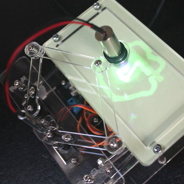
Elektor Labs Elektor Laser Head Upgrade for Sand Clock
The Elektor Laser Head transforms the Elektor Sand Clock into a clock that writes the time on glow-in-the-dark film instead of sand. In addition to displaying the time, it can also be used to create ephemeral drawings. The 5 mW laser pointer, with a wavelength of 405 nm, produces bright green drawings on the glow-in-the-dark film. For best results, use the kit in a dimly lit room. Warning: Never look directly into the laser beam! The kit includes all the necessary components, but soldering three wires is required. Note: This kit is also compatible with the original Arduino-based Sand Clock from 2017. For more details, see Elektor Magazine 1-2/2017 and Elektor Magazine 1-2/2018.
€ 34,95€ 24,95Best Price
-
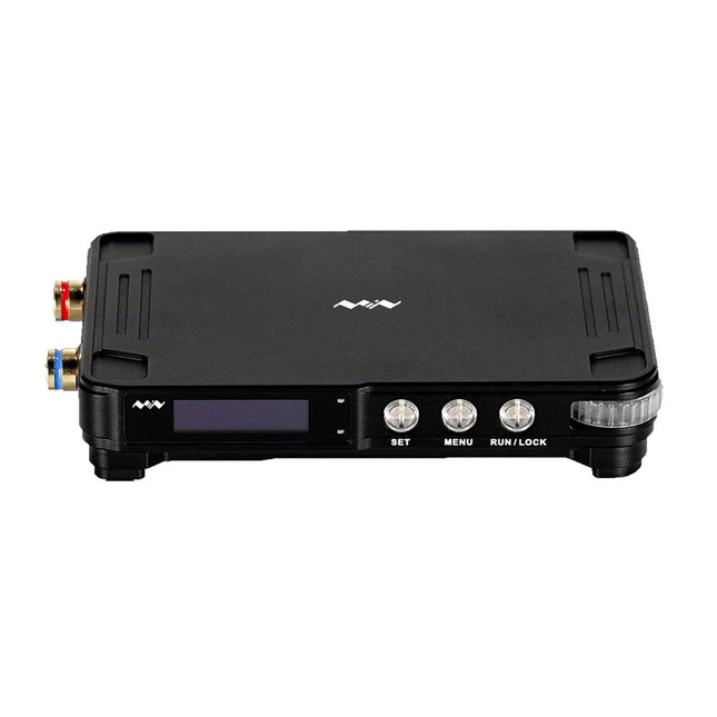
Miniware Miniware MDP-P906 Digital Power Supply (300 W)
MDP-P906 has a built-in cooling fan, and maximum output power of up to 300 W, which meets a wider range of testing needs and application scenarios. Through 2.4 GHz wireless communication, it can be connected to MDP-M01 Smart Digital Monitor module to realize the free combination of multiple channels of 300 W per channel. MDP-P906 has the index, stability and reliability comparable to a professional power supply. It can output pure current, and provide powerful functions such as programmable output, timing output, timing control, automatic compensation, boost mode, etc., making itself a real cost-effective, smart and customized programmable linear DC power supply. MDP-P906 adopts a precision CNC machined aluminum alloy shell, with fine workmanship, novel, mini and beautiful appearance, it completely subverts the rigid image of traditional desktop power supply. With stackable modular design and wireless communication function, MDP-P906 can work independently or paired, both on the workbench, and be carried out for on-site maintenance. MDP-P906 is a perfect solution for electronic engineer, especially field application engineers to meet different needs of power sources. Built-in silent cooling fan, instant cooling, ensure a stable and efficient output! Smart linear compensation, constant voltage & constant current Positive & negative output, series boost, parallel current sharing Applications Universal tests and teaching experiments in R&D laboratory Maintenance of digital products Property verification and fault diagnosis of devices and circuits Emergency power supply for model airplanes and vehicles Power supply testing of RF and microwave circuits or modules Quality control and quality inspection Supply purified power for high-accuracy digital-analog hybrid circuits and Hi-Fi audio devices Specifications Input DC 4.2-30 V/14 A (Max)QC 3.0/PD2.0, 20 V/5 A (Max) Output 0-30 V/0-10 A, 300 W (Max) Conversion efficiency 95% Output resolution 10 mV/2 mA, up to 1 mV/1 mA via Display Control module Output accuracy 0.03%+5 mV0.05%+2 mV Adjustment rate Load adjustment rate <±0.01%Power adjustment rate <±0.01% Ripple and noise <250 uVrms, 3 mVpp; 2 mArms Transient response <4 uS Safety protections Input over-voltage, under-voltage, reverse connection protection, output over-current, back-flow protection and over-temperature protection Others Automatically shut-down and enter micro-power modeSupport USB firmware upgrade Dimensions 112 x 66 x 20 mm Weight 181 g Included 1x MDP-P906 Digital Power Supply 2x Output Cable 1x User Manual Downloads User Manual v1.1 Firmware v1.32
€ 171,95
-
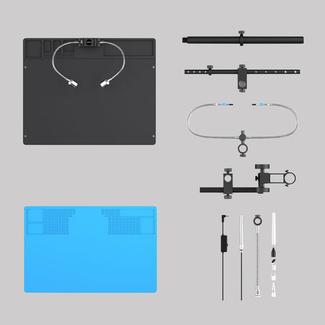
Andonstar Andonstar Max Station Upgrade Set for AD409 Models
Upgrade your Andonstar AD409, AD409 Pro, or AD409 Pro-ES to the Max model with this enhancement kit. The newly designed, oversized Max station provides ample workspace, making it perfect for larger projects and ideal for professional soldering tasks. Included 1x Stand with 2 LEDs 1x Repair mat 1x Beam 1x Column 1x Tool holder 1x Soldering Helping Hands
€ 60,00
-
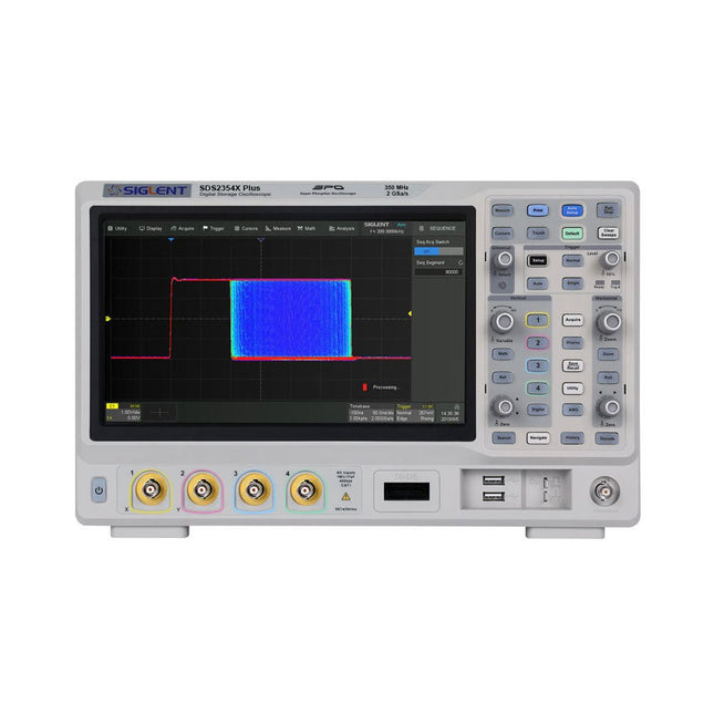
Siglent Siglent SDS2354X Plus 4-ch Oscilloscope (350 MHz)
Siglent's SDS2000X Plus series Digital Storage Oscilloscopes are available in bandwidths of 100 MHz, 200 MHz, and 350 MHz, have a maximum sample rate of 2 GSa/s, a maximum record length of 200 Mpts/ch, and up to 4 analog channels + 16 digital channels mixed-signal analysis ability. The SDS2000X Plus series employs Siglent’s SPO technology with a maximum waveform capture rate of up to 120,000 wfm/s (normal mode, up to 500,000 wfm/s in Sequence mode), 256-level intensity grading display function plus a color temperature display mode. It also employs an innovative digital trigger system with high sensitivity and low jitter. The trigger system supports multiple powerful triggering modes including serial bus triggering. History waveform recording, Sequence acquisition, Search and Navigate functions allow for extended waveform records to be captured, stored, and analyzed. An impressive array of measurement and math capabilities, options for a 50 MHz waveform generator, as well as serial decoding, mask test, bode plot, and power analysis are also features of the SDS2000X Plus. A 10-bit acquisition mode helps to satisfy applications that require more than 8-bit resolution. The large 10.1" capacitive touch screen supports multi-touch gestures, while the remote web control, mouse and external keyboard support greatly improve the operating efficiency of the SDS2000X Plus. Features 100 MHz, 200 MHz, 350 MHz (upgradable to 500 MHz) models Real-time sampling rate up to 2 GSa/s Record length up to 200 Mpts Serial bus triggering and decoder, supports I²C, SPI, UART, CAN, LIN, CAN FD, FlexRay, I²S and MIL-STD-1553B Provide 10 bit mode, Vertical and Horizontal Zoom Capacitive touch screen supports multi-touch gestures Siglent SDS2000X Plus Oscilloscopes SDS2102X Plus SDS2104X Plus SDS2204X Plus SDS2354X Plus Bandwidth 100 MHz 100 MHz 200 MHz 350 MHz Channels 2 4 4 4 Real-time sampling rate 2 GSa/s 2 GSa/s 2 GSa/s 2 GSa/s Capture rate 120,000 wfm/s 120,000 wfm/s 120,000 wfm/s 120,000 wfm/s Memory depth 200 Mpts/ch 200 Mpts/ch 200 Mpts/ch 200 Mpts/ch Included Siglent SDS2354X Plus Oscilloscope Passive probes Power cord USB cable Manual Downloads Datasheet Manual Quick guide Manual Firmware
€ 2.515,83
-
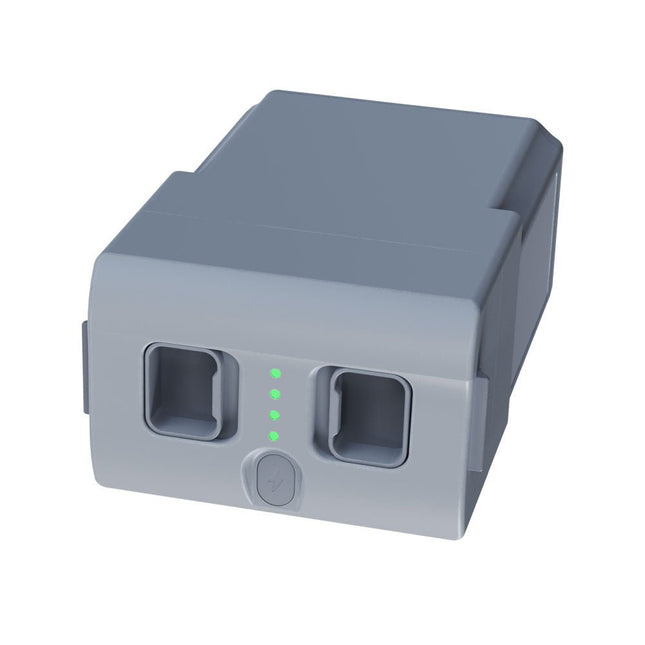
Unitree Unitree Go2 Spare Battery (15,000 mAh)
With a capacity of 15,000 mAh, the Unitree Go2 battery provides a robust power source that enables your robot to complete tasks with ease. Whether for complex exploration, research projects, or fun excursions, this powerful battery delivers the energy your robot needs. The runtime of the Unitree Go2 battery varies depending on the application and usage. Based on the functions and activities employed, the battery can offer between 2 to 4 hours of operation. This flexibility allows you to customize the robot as needed, enabling longer exploration missions or more extensive projects. The Unitree Go2 battery is a reliable companion for your robotics adventures. With its impressive capacity and adaptable runtime, it ensures your robot performs powerfully and with endurance, without frequent recharging. Whether you need the Unitree Go2 battery as a replacement or an upgrade for your robot, this powerful energy storage solution provides the perfect balance of performance and reliability. Specifications Rated voltage: DC 28.8 V Limited charging voltage: DC 33.6 V Charging current: 9 A Rated capacity: 15,000 mAh, 432 Wh Standard: IS 16046 (Part 2) / IEC 62133-2 Self-developed battery management system (BMS) Dimensions: 120 x 80 x 182 mm Functions: Power indicator Self-discharge protection of battery storage Equilibrium charge protection Overcharge protection Discharge protection Short circuit protection Battery charge detection protection
€ 795,00
Best Price
-

Red Pitaya Red Pitaya STEMlab 125-14 PRO Gen 2 Starter Kit (incl. Book)
This bundle includes the Red Pitaya STEMlab 125-14 PRO Gen 2 Starter Kit and the new book "Experimenting with Red Pitaya STEMlab Gen 2". The Red Pitaya STEMlab 125-14 PRO Gen 2 Starter Kit is a powerful and flexible platform for signal processing, data acquisition, and electronic measurement applications. Designed for engineers, developers, researchers, and educators, this kit provides everything required to start building advanced measurement and control systems. At the core of the kit is the STEMlab 125-14 PRO Gen 2 board, an upgraded and ultra-lightweight development platform. Powered by the Xilinx Zynq-7010 SoC with 512 MB of RAM, it combines FPGA programmability with ARM processing power to enable high-performance instrumentation and custom signal-processing solutions. The board offers 14-bit ADC and DAC resolution, a 125 MS/s sampling rate, an input range of ±20 V, and up to 60 MHz bandwidth. Its improved low-noise analog front-end, USB-C connectivity, and compact design make it suitable for demanding applications such as RF development, radar systems, photonics research, software-defined radio (SDR), and industrial automation. The Starter Kit includes all essential accessories for immediate use: a microSD card with preinstalled operating system, power supply, Ethernet cable for remote access, two 100 MHz oscilloscope probes, and SMA-to-BNC adapters for flexible signal connections. The Red Pitaya STEMlab 125-14 PRO Gen 2 Starter Kit is an excellent platform for rapid prototyping, FPGA development, measurement instrumentation, and advanced electronics experimentation. Features 14-bit ADC and DAC resolution 125 MS/s sampling rate ±20 V input range Up to 60 MHz bandwidth Xilinx Zynq-7010 SoC (FPGA + ARM processor) 512 MB RAM Low-noise analog front- and back-ends Applications RF development and testing Radar and wireless systems Software-defined radio (SDR) Photonics and optical research Industrial automation and control systems Signal analysis and instrumentation Rapid prototyping of electronic measurement systems Specifications Processor Dual-core ARM Cortex-A9 FPGA AMD Xilinx Zynq-7010 SoC RAM 512 MB (4 Gb) Storage microSD card (up to 32 GB) Operating System Linux-based Red Pitaya OS ADC Resolution 14-bit DAC Resolution 14-bit Bandwidth 60 MHz (DC) Sampling Rate 125 MS/s Analog Input Channels 2 Analog Output Channels 2 Input Voltage Range ±1 V (LV) / ±20 V (HV) Input Impedance 1 MΩ / 10 pF Output Voltage Range ±1 V Ethernet 1x Gigabit Ethernet (RJ45) USB 2x USB-C 2.0 (for power and console) Digital I/O 16x GPIO (3.3 V) Communication Interfaces I²C, SPI, UART, CAN Power Supply 5 V/3 A via USB-C Dimensions 106.8 x 60.0 x 17.9 mm Included 1x Red Pitaya STEMlab 125-14 PRO Gen 2 board 2x 100 MHz oscilloscope probes 2x SMA-to-BNC adapters 1x microSD card with preinstalled OS 1x USB-C Power supply 1x Ethernet cable Downloads Documentation Schematics Book: Experimenting with Red Pitaya STEMlab Gen 2 With this new book, Red Pitaya goes beyond a versatile board. It becomes a powerful laboratory instrument for precision measurement, analysis, and control. From the fundamentals of electronic project development, monitoring, control, and design to testing, this book walks you step-by-step through everything you need to know to harness the full potential of Red Pitaya hardware and software. The book presents real-time, FPGA-based projects that are developed on a PC using the Vivado environment, then transferred to the Red Pitaya for execution and testing. You will learn about enhanced performance, expanded I/O capabilities, improved FPGA features, and advanced connectivity options that open up new frontiers for precision measurement, monitoring, and control in your embedded applications. Inside the book you will discover: A deep dive into Red Pitaya architecture and hardware design Electronic experiments using Red Pitaya for measurement and monitoring Hands-on projects using the Python programming language Practical guidance for FPGA programming using Red Pitaya Red Pitaya FPGA projects using the Verilog HDL under Vivado IDE Practical design of electronic projects including measurement and testing Step-by-step examples that bridge theory and real-world implementation Whether you are designing your own electronic circuits, developing signal analysis tools, or creating real-time control or monitoring systems, this book provides you the knowledge and confidence you need to fully learn and customize the Red Pitaya platform.










-
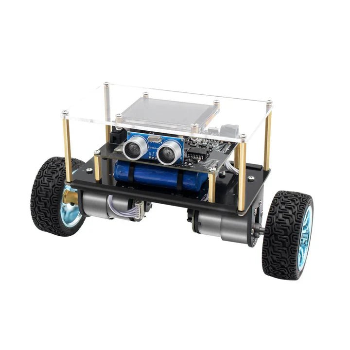
, by Lobna Belarbi Affordable Robot Kits to Kickstart Your Robotics Journey
Robotics is an exciting and rewarding field, but getting started can be intimidating—especially when it comes to choosing the right kit. Fortunately, Elektor offers a...
-

, by Beatriz Sousa Enhanced Shopping Experience! Welcome to the new Elektor Store.
We are pleased to inform you that the new Elektor Store website is now live! The updates to our store are a direct result of...

