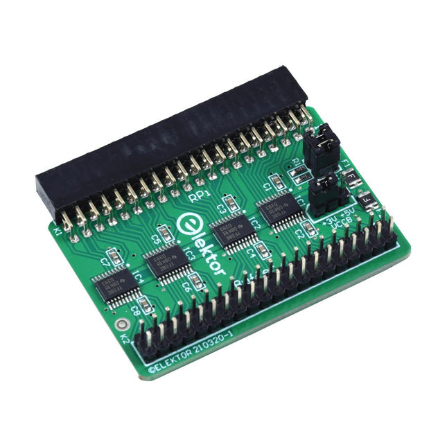
When you experiment with the Raspberry Pi on a regular basis and you connect a variety of external hardware to the GPIO port via the header you may well have caused some damage in the past. The Elektor Raspberry Pi Buffer Board is there to prevent this! The board is compatible with Raspberry Pi Zero, Zero 2 (W), 3, 4, 5, 400 and 500.
All 26 GPIOs are buffered with bi-directional voltage translators to protect the Raspberry Pi when experimenting with new circuits. The PCB is intended to be inserted in the back of Raspberry Pi 400/500. The connector to connect to the Raspberry Pi is a right angled 40-way receptacle (2x20). The PCB is only a fraction wider. A 40-way flat cable with appropriate 2x20 headers can be connected to the buffer output header to experiment for instance with a circuit on a breadboard or PCB.
The circuit uses 4x TXS0108E ICs by Texas Instruments. The PCB can also be put upright on a Raspberry Pi.
Downloads
Schematics
Layout
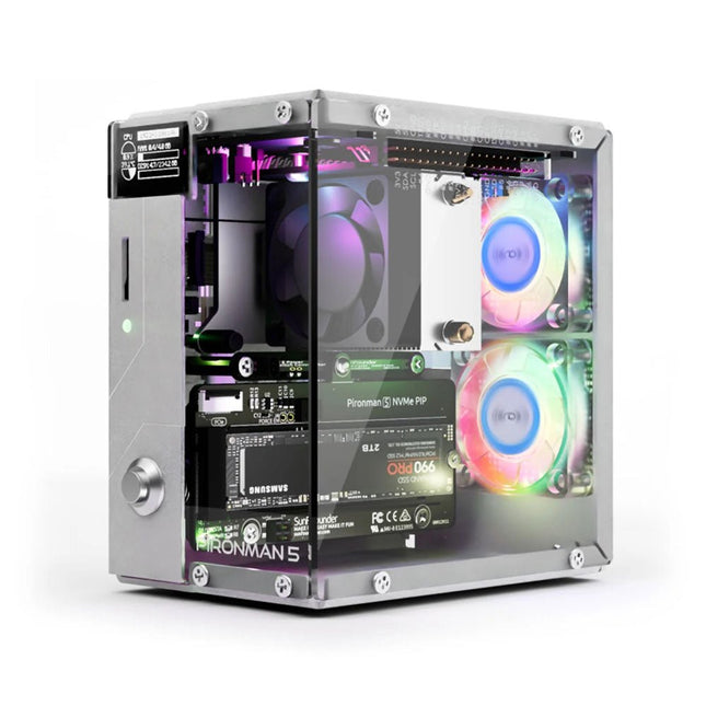
Enhance your Raspberry Pi 5 with the Pironman 5, built with sturdy aluminum, superior cooling, NVMe M.2 SSD support, OLED display, RGB lighting, standard HDMI ports x2, and a secure power switch. It is perfect for NAS, Home Assistant, Media and Game Centers. The Pironman 5 is not just a case; it’s an upgrade that transforms your Raspberry Pi 5 into a powerful, efficient, and stylish device.
The Pironman 5 includes the Pi 5 NVMe PIP (PCIe Peripheral Board), a PCIe adapter board specifically designed for NVMe solid-state drives. This board supports four sizes of NVMe SSDs: 2230, 2242, 2260, and 2280, all of which can be installed in an M.2 M key slot. The connection is certified for Gen 2.0 speeds (5 GT/sec), but can be forced to Gen 3.0 (10 GT/sec) for faster performance.
Expandable NVMe M.2 SSD Slot
Boost your Raspberry Pi 5's performance with the Pironman 5's NVMe M.2 SSD slot, supporting multiple sizes (2230, 2242, 2260, 2280) for increased storage and faster system response.
Advanced Cooling System
Keep your Raspberry Pi 5 cool and stylish with the Pironman 5's tower cooler and dual RGB fans, featuring dust filters for durable, low-maintenance operation.
OLED Display for Instant Insights
The Pironman 5 includes a 0.96" OLED display, providing immediate updates on CPU and RAM usage, temperature, IP address, and more.
Enhanced Functionality and Safety
The Pironman 5 secures your Raspberry Pi 5 with features like safe shutdown, customizable RGB LEDs, HDMI ports, an IR receiver, and an external GPIO extender, enhancing functionality and connectivity.
Features
Raspberry Pi 5 mini PC
0.96" OLED Display showing Raspberry Pi’s CPU usage, temperature, disk usage, IP address, RAM usage etc.
Tower cooler can cool a 100% CPU load Pi to 39°C at 25°C room temperature
2 RGB Fans, with GPIO control
1 PWM Fan on the Tower Cooler is controlled by the Raspberry Pi system.
Supports four (PCIe Gen 2.0 / PCIe Gen 3.0) NVMe M.2 SSD sizes: 2230, 2242, 2260, and 2280.
4 WS2812 Addressable RGB LED light up the whole case with cool light effect
IR Receiver for multi-media center like Kodi or Volumio
Retro metal power button for safe shut down
External GPIO extender with pin name label, for easy access
Equipped with a spring-loaded socket for easy card removal
Aluminum main body with clear Acrylic side panel
Features two standard HDMI ports
Downloads
Documentation
Build Your Own Vintage Radio Broadcaster
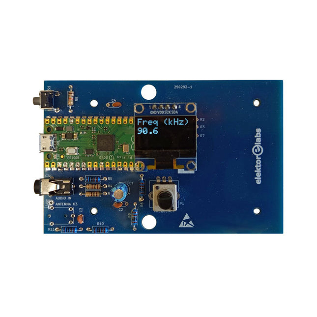
The Elektor AM Transmitter Kit allows streaming audio to vintage AM radio receivers. Based on a Raspberry Pi Pico microcontroller module, the AM Transmitter can transmit on 32 frequencies in the AM band, from 500 kHz up to 1.6 MHz in 32 steps of approx. 35 kHz.
The frequency is selected with a potentiometer and shown on a 0.96" OLED display. A pushbutton allows toggles the transmitting mode between On and Off. The range of the transmitter depends on the antenna. The onboard antenna provides a range of a few centimeters, requiring the AM Transmitter to be placed close to or inside the radio. An external loop antenna (not included) can be connected to increase the range.
The Elektor AM Transmitter Kit comes as a kit of parts that you must solder to the board yourself.
Features
The board is compatible with a Hammond 1593N enclosure (not included).A 5 VDC power supply with micro-USB connector (e.g., an old phone charger) is needed to power the kit (not included). Current consumption is 100 mA.
The Arduino software (requiring Earle Philhower’s RP2040 Boards Package) for the Elektor AM Transmitter Kit plus more information is available at the Elektor Labs page of this project.
Component List
Resistors
R1, R4 = 100 Ω
R2, R3, R8 = 10 kΩ
R5, R6, R9, R10, R11 = 1 kΩ
R7 = optional (not included)
P1 = potentiometer 100 kΩ, linear
Capacitors
C1 = 22 µF 16V
C2, C4 = 10 nF
C3 = 150 pF
Miscellaneous
K1 = 4×1 pin socket
K2, K3 = 3.5 mm socket
Raspberry Pi Pico
pushbutton, angle mount
0.96" monochrome I²C OLED display
PCB 150292-1
This bundle contains the popular Elektor Sand Clock for Raspberry Pi Pico and the new Elektor Laser Head Upgrade, offering even more options for displaying the time. Not only can you "engrave" the current time in sand, you can now alternatively write it on a glow-in-the-dark foil or create green drawings.
Contents of the bundle
Elektor Sand Clock for Raspberry Pi Pico (normal price: €50)
Elektor Laser Head Upgrade for Sand Clock (normal price: €35)
Elektor Sand Clock for Raspberry Pi (Raspberry Pi-based Eye Catcher)
A standard sand clock just shows how time passes. In contrast, this Raspberry Pi Pico-controlled sand clock shows the exact time by "engraving" the four digits for hour and minute into the layer of sand. After an adjustable time the sand is flattened out by two vibration motors and everything begins all over again.
At the heart of the sand clock are two servo motors driving a writing pen through a pantograph mechanism. A third servo motor lifts the pen up and down. The sand container is equipped with two vibration motors to flatten the sand. The electronic part of the sand clock consists of a Raspberry Pi Pico and an RTC/driver board with a real-time clock, plus driver circuits for the servo motors.
A detailed construction manual is available for downloading.
Features
Dimensions: 135 x 110 x 80 mm
Build time: approx. 1.5 to 2 hours
Included
3x Precut acrylic sheets with all mechanical parts
3x Mini servo motors
2x Vibration motors
1x Raspberry Pi Pico
1x RTC/driver board with assembled parts
Nuts, bolts, spacers, and wires for the assembly
Fine-grained white sand
Elektor Laser Head Upgrade for Sand Clock
The new Elektor Laser Head transforms the Sand Clock into a clock that writes the time on glow-in-the-dark film instead of sand. In addition to displaying the time, it can also be used to create ephemeral drawings. The 5 mW laser pointer, with a wavelength of 405 nm, produces bright green drawings on the glow-in-the-dark film. For best results, use the kit in a dimly lit room. Warning: Never look directly into the laser beam!
The kit includes all the necessary components, but soldering three wires is required.
Note: This kit is also compatible with the original Arduino-based Sand Clock from 2017. For more details, see Elektor Magazine 1-2/2017 and Elektor Magazine 1-2/2018.
Book: Logic Analyzers in Practice
Step-by-step instructions guide you through the analysis of modern protocols such as I²C, SPI, UART, RS-232, NeoPixel, WS28xx, HD44780 and 1-Wire. With the help of numerous experimental circuits based on the Raspberry Pi Pico, Arduino Uno and the Bus Pirate, you will learn the practical application of popular USB logic analyzers.
All the experimental circuits presented in this book have been fully tested and are fully functional. The necessary program listings are included – no special programming or electronics knowledge is required for these circuits. The programming languages used are MicroPython and C along with the development environments Thonny and Arduino IDE.
This book uses several models of flexible and widely available USB logic analyzers and shows the strengths and weaknesses of each price range.
You will learn about the criteria that matter for your work and be able to find the right device for you.
Whether Arduino, Raspberry Pi or Raspberry Pi Pico, the example circuits shown allow you to get started quickly with protocol analysis and can also serve as a basis for your own experiments.
After reading this book, you will be familiar with all the important terms and contexts, conduct your own experiments, analyze protocols independently, culminating in a comprehensive knowledge set of digital signals and protocols.
USB Logic Analyzer (8-ch, 24 MHz)
This USB Logic Analyzer is an 8-channel logic analyzer with each input dual purposed for analog data recording. It is perfect for debugging and analyzing signals like I²C, UART, SPI, CAN and 1-Wire. It operates by sampling a digital input connected to a device under test (DUT) at a high sample rate. The connection to the PC is via USB.
Specifications
Channels
8 digital channels
Maximum sampling rate
24 MHz
Maximum input voltage
0 V ~ 5 V
Operating temperature
0°C ~ 70°C
Input impedance
1 MΩ || 10 pF
Supported protocols
I²C, SPI, UART, CAN, 1-Wire, etc.
PC connection
USB
Dimensions
55 x 28 x 14 mm
Downloads
Software
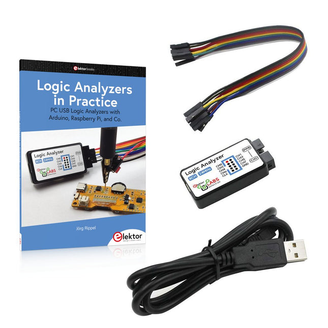
This bundle contains:
Book 'Logic Analyzers in Practice' (normal price: €35)
USB Logic Analyzer (8-ch, 24 MHz) (normal price: €20)
USB Cable
Jumper Wire Ribbon Cable
Build Your Own RISC-V ControllerFirst Steps with the NEORV32 RISC-V Softcore for Low-Cost FPGAs
How to Use Arduino’s Serial PlotterPlotting Graphs With Arduino Is Easy
CLUE from AdafruitA Smart Solution for IoT Projects
Buffer Board for the Raspberry Pi 400Protect the I/Os Raspberry Pi RP2040 Boards Aplenty
A Handbook on DIY Electronic Security and EspionageSRAM Heated or Deep-Frozen
Component IdentificationTips & Tricks, Best Practices and Other Useful Information DIY Touchless Light Switch
Starting out in ElectronicsMatching and Transforming
What’s New in Embedded Development?Rust and Keeping IoT Deployments Updated Infographics How the Industrial and Automotive Sectors Will Benefit from 5G
Moving Coil RelaysPeculiar Parts, the series
HomeLab ToursEverything Revolves Around the Tools...
Understanding the Neurons in Neural Networks (Part 4)Embedded Neurons
Magnetic Levitation the Very Easy WayThe Third and Most Compact Version
PLC Programming with the Raspberry Pi and the OpenPLC ProjectVisualization of PLC Programs with AdvancedHMI
From Life's ExperiencePack Up and Leave
Under Your RadarMicrocontrollers You Should Know About
Monitor and Debug Over the AirA Solution for Arduino, ESP32 and Co.
Portable Temperature- and Humidity-Measuring DeviceUsing Ready-Made Modules
Lithium Battery Pack RepairSave Money + More Power!
GUIs with PythonMeme-Generator
Three Questions to Build OnWhy, What, and Who?
HexadokuThe Original Elektorized Sudoku
Buch: Logic Analyzer im Einsatz
Schritt-für-Schritt-Anleitungen führen Sie in die Analyse moderner Protokolle von I²C, SPI, UART, RS-232, NeoPixel, WS28xx, HD44780 und 1-Wire ein. Anhand von zahlreichen Experimentierschaltungen mit dem Raspberry Pi Pico, Arduino Uno und dem Bus Pirate üben Sie die praxisnahe Anwendung gängiger USB-Logikanalysatoren ein.
Alle in diesem Buch vorgestellten Experimentierschaltungen wurden vollständig getestet und sind funktionsfähig. Die notwendigen Programmlistings sind enthalten, es sind keine besonderen Programmier- oder Elektronikkenntnisse für diese Schaltungen notwendig. Es werden die Programmiersprachen MicroPython und C mit den Entwicklungsumgebungen Thonny und Arduino IDE eingesetzt.
Dieses Buch verwendet mehrere Modelle flexibler und weit verbreiteter USB-Logikanalysatoren und zeigt die Stärken und Schwächen jeder Preisklasse. Sie werden kennenlernen, welche Kriterien für Ihre Arbeit wichtig sind und in der Lage sein, das für Sie passende Gerät zu finden.
Egal ob Arduino, Raspberry Pi oder Raspberry Pi Pico: Die abgebildeten Beispielschaltungen ermöglichen einen schnellen Start in die Protokollanalyse und können auch als Grundlage für eigene weitere Experimente dienen.
Sie werden alle wichtigen Begriffe und Zusammenhänge kennenlernen, eigene Experimente durchführen, selbstständig Protokolle analysieren und nach der Lektüre dieses Buches – im Bereich der digitalen Signale und Protokolle – ein umfassendes Wissen aufgebaut haben.
USB Logic Analyzer (8 Kanäle, 24 MHz)
Dieser USB Logic Analyzer ist ein 8-Kanal-Logikanalysator, bei dem jeder Eingang doppelt für die analoge Datenaufzeichnung dient. Es eignet sich perfekt zum Debuggen und Analysieren von Signalen wie I²C, UART, SPI, CAN und 1-Wire. Dabei wird ein digitaler Eingang, der mit einem zu testenden Gerät (DUT) verbunden ist, mit einer hohen Abtastrate abgetastet. Die Verbindung zum PC erfolgt via USB.
Technische Daten
Kanäle
8 digitale Kanäle
Maximale Abtastrate
24 MHz
Maximale Eingangsspannung
0 V ~ 5 V
Betriebstemperatur
0°C ~ 70°C
Eingangsimpedanz
1 MΩ || 10 pF
Unterstützte Protokolle
I²C, SPI, UART, CAN, 1-Wire etc.
PC-Verbindung
USB
Abmessungen
55 x 28 x 14 mm
Downloads
Software
Dieses Bundle enthält:
Buch: Logic Analyzer im Einsatz (Einzelpreis: 40 €)
USB Logic Analyzer (8 Kanäle, 24 MHz) (Einzelpreis: 20 €)
USB-Kabel
Jumper Wire Ribbon Kabel
Book: Mastering the Arduino Uno R4
Based on the low-cost 8-bit ATmega328P processor, the Arduino Uno R3 board is likely to score as the most popular Arduino family member, and this workhorse has been with us for many years. Eleven years later, the long-overdue successor, the Arduino Uno R4, was released. It is built around a 48 MHz, 32-bit Arm Cortex-M4 microcontroller and provides significantly expanded SRAM and Flash memory. Additionally, a higher-precision ADC and a new DAC are added to the design. The Uno R4 board also supports the CAN Bus with an interface.
Two versions of the board are available: Uno R4 Minima, and Uno R4 WiFi. This book is about using these new boards to develop many different and interesting projects with just a handful of parts and external modules. All projects described in the book have been fully tested on the Uno R4 Minima or the Uno R4 WiFi board, as appropriate.
The project topics include the reading, control, and driving of many components and modules in the kit as well as on the relevant Uno R4 board, including
LEDs
7-segment displays (using timer interrupts)
LCDs
Sensors
RFID Reader
4x4 Keypad
Real-time clock (RTC)
Joystick
8×8 LED matrix
Motors
DAC (Digital-to-analog converter)
LED matrix
WiFi connectivity
Serial UART
CAN bus
Infrared controller and receiver
Simulators
… all in creative and educational ways with the project operation and associated software explained in great detail.
Arduino Uno R4 WiFi
The Arduino Uno R4 is powered by the Renesas RA4M1 32-bit ARM Cortex-M4 processor, providing a significant boost in processing power, memory, and functionality. The WiFi version comes with an ESP32-S3 WiFi module in addition to the RA4M1, expanding creative opportunities for makers and engineers.
The Arduino Uno R4 runs at 48 MHz, which provides a 3x increase over the popular Uno R3. Additionally, SRAM has been upgraded from 2 kB to 32 kB, and flash memory from 32 kB to 256 kB to support more complex projects. Responding to community feedback, the USB port is now USB-C, and the maximum power supply voltage has been raised to 24 V with an enhanced thermal design. The board includes a CAN bus and an SPI port, enabling users to reduce wiring and perform parallel tasks by connecting multiple shields. A 12-bit analog DAC is also provided on the board.
Specifications
Microcontroller
Renesas RA4M1 (ARM Cortex-M4)
USB
USB-C
Programming Port
Pins
Digital I/O Pins
14
Pins
Analog input pins
6
DAC
1
RTC
1
PWM pins
6
Communication
UART
1x
I²C
1x
SPI
1x
Qwiic I²C connector
1x
CAN
1x CAN Bus
Power
Circuit operating voltage
5 V
Input voltage (VIN)
6-24 V
DC Current per I/O Pin
8 mA
Clock speed
Main core
48 MHz
Memory
RA4M1
256 kB Flash, 32 kB RAM
LED Matrix
12 x 8 (96 red LEDs)
Dimensions
68.9 x 53.4 mm
Downloads
Datasheet
Schematics
This bundle contains:
Book: Mastering the Arduino Uno R4 (normal price: €45)
Arduino Uno R4 WiFi (normal price: €30)
This bundle includes the Arduino UNO Q (2 GB) and the book "Arduino UNO Q and AI".
The Arduino UNO Q is the first UNO board with a hybrid dual-brain architecture, combining a powerful Linux processor with a real-time microcontroller – bringing advanced computing and precise control together on one board.
Powered by a Qualcomm Dragonwing QRB2210 MPU running Debian Linux and a STM32U585 MCU for real-time tasks, the UNO Q is built for next-generation applications. From Edge Computing and AI to robotics and automation, it delivers high performance without sacrificing ease of use.
Simply connect your peripherals and get started – no extra hardware required.
Features
Dual-core architecture: Linux MPU + real-time MCU
Qualcomm Dragonwing QRB2210 with Debian Linux support
STM32U585 microcontroller for deterministic control
Runs Arduino sketches via Zephyr OS
Ideal for AI, IoT, robotics, and industrial projects
Specifications
Microprocessor (MPU)
Qualcomm Dragonwing QRB2210:Quad-core Arm Cortex-A53 @ 2.0 GHzAdreno GPU 3D graphics accelerator2× ISP (13 MP + 13 MP or 25 MP) @ 30 fps
Microcontroller (MCU)
STM32U585Arm Cortex-M33 up to 160 MHz2 MB flash memory786 KB SRAM
RAM
2 GB LPDDR4
Power Supply
From USB-C connector 5 V max at 3 AInput Voltage (VIN): 7-24 V
Storage
16 GB eMMC
USB
1× USB-C port with host/device role switching, power role switch and video output
Connectivity
Wi-Fi 5 (2.4/5 GHz) with onboard antennaBluetooth 5.1 with onboard antenna
Interfaces
I²C/I³CSPIPWMCANUARTPSSIGPIOJTAGADC
Video
Video output support via USB-CMIPI DSI pins on JMEDIA header
Extra
4× RGB user-controllable LEDs8×13 Blue LED Matrix1× Qwiic connector voltage 3V3, I²C1× User push-buttonJCTL: MPU Remote Debug connector
Audio
Microphone IN / Headphone OUT / Line OUT on JMISC
MPU Operating System
Linux Debian OS with upstream support
Real-time Operating System
Arduino Core on Zephyr OS
Containerization
Docker and Docker Compose support
Support Operating Systems for Arduino App Lab
Windows: Windows 10 or later (64-bit)macOS: macOS 11 or later (64-bit)Linux: Ubuntu 22.04 or later, and Debian Trixie (64-bit)
Dimensions
68.85 × 53.34 mm (UNO form factor)
Downloads
Datasheet
User Manual
Pinout
Schematics
Book: Arduino UNO Q and AI – Learn to Build Intelligent Embedded Systems
Build smarter embedded systems with Arduino UNO Q. This book gives you the tools, knowledge, and confidence to turn ideas into intelligent, working solutions using the Arduino UNO Q platform. Discover how to build intelligent embedded systems with the Arduino UNO Q and AI.
Unlock the full potential of the Arduino UNO Q, a next-generation platform that combines the real-time power of the STM32U585 microcontroller with the flexibility of a Qualcomm Dragonwing QRB2210 microprocessor.
Learn how to rapidly prototype real-world applications using the Arduino IDE for low-level embedded control and Python in Arduino App Lab for high-level development.
Build confidence through hands-on projects that guide you step by step from basic board features to complete working systems.
Explore ready-to-use, AI based Arduino App Lab examples and see how they can jump-start your development and reduce time to deployment.
Step into the world of Edge AI with a clear, practical introduction to Edge Impulse Studio—no prior AI experience required.
Follow a complete, real-world workflow to create a Keyword Spotting AI application, covering data collection, model training, optimization, and on-device inference using the Edge Impulse Studio.
Bridge the gap between embedded systems and machine learning and learn how to bring intelligence directly onto your hardware.
Perfect for embedded engineers, educators, students, and makers looking to stay ahead in AI-enabled product development.
This bundle contains:
Arduino UNO Q (2 GB) (normal price: €50)
Book: Arduino UNO Q and AI (normal price: €35)
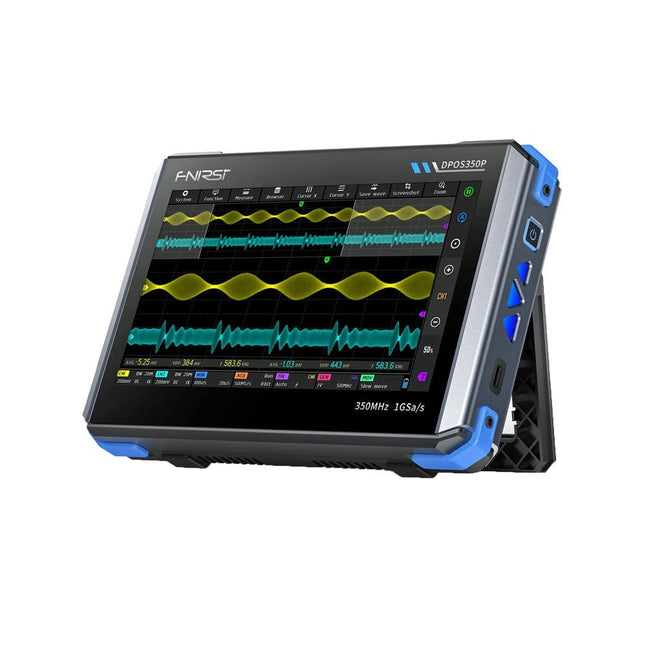
2 Channels • 350 MHz • 1 GSa/s • 50,000 wfm/s • 7 inch Touchscreen
The FNIRSI DPOS350P is a sleek 4-in-1 powerhouse in tablet form! This compact and portable device packs serious functionality: it combines a 2-channel oscilloscope (350 MHz), a signal generator (50 MHz), a frequency response analyzer (50 MHz), and a spectrum analyzer (200 kHz–350 MHz) – all in one unit.
Whether you're in R&D, troubleshooting, or field testing, the DPOS350P delivers the tools you need to measure, generate, analyze, and visualize electronic signals with precision and clarity. Its responsive high-resolution touchscreen and intuitive controls make signal analysis fast, flexible and efficient.
Features
Powerful Multi-Function Integration
350 MHz 2-channel oscilloscope with 1 GSa/s real-time sampling
50 MHz signal generator with 14 standard + custom waveforms
Spectrum analyzer (200 kHz–350 MHz): Perfect for EMI, RF & HF testing
Frequency response analyzer (FRA) up to 50 MHz
High-Performance Waveform Capture
50,000 wfm/s refresh rate for real-time signal clarity
350 MHz bandwidth (single-channel mode)
Detects rare and low-probability anomalies
Crisp Display & Smooth Operation
7" IPS touchscreen (1024 x 600 resolution)
Switch between grayscale and color temperature display
Easy to operate in various test environments
Reliable, Protected & Fast-Charging
High-voltage protection up to 400 V
Fast charging with QC 18 W (full charge in 2 hours)
Built for stable long-term operation
Data Storage & Export
Save up to 500 waveform records + 90 screenshots
USB export for easy reporting and offline analysis
Specifications
General
Display
7 inch (IPS full viewing angle)
Resolution
1024 x 600 pixels
Interaction mode
Capacitive touch screen
Total power consumption
10 W
Power-on configuration
5 presets
Charging
QC 18 W, 12 V/1.5 A (USB-C)
Battery
3.7 V, 8000 mAh lithium battery
Battery life
approx. 3 hours in operation, 5 hours standby
Heat dissipation
Air cooling
Expansion interface
USB data port
Automatic shutdown
15~60 minutes / off
Firmware upgrade
Support .iso image upgrade
Languages
English / Portuguese / Russian / Chinese
Dimensions
190 x 128 x 37 mm
Oscilloscope
Analog channels
2
Analog bandwidth
350 MHz
Rise time
1ns
Real-time sampling rate
1 GSa/s
Memory depth
60 Kpts
Input impedance
1 MΩ / 14PF
Time base range
5ns ~ 50s
Roll time base
50ms ~ 50s
Vertical sensitivity
2 mV ~ 20 V (1X)
Vertical range
16 mV ~ 160 V (1X)
DC accuracy
±2%
Time accuracy
±0.01%
Input coupling
DC / AC
Probe attenuation
1X / 10X / 100X
Hardware bandwidth limit
150M / 20M
High resolution mode
8bit ~ 16bit
Parameter measurements
12 types
Cursor measurement
Time, period, frequency, level, voltage
Trigger detection
Digital trigger
Trigger channel
CH1 / CH2
Trigger mode
Auto / Single / Normal
Trigger edge
Rising edge / Falling edge
Trigger suppression
L1 ~ L3
Trigger level
Manual / automatic 10% ~ 90%
Screenshot storage
90 pictures
Waveform storage
500 groups
Background grid
Display / hide
Waveform movement
Coarse adjustment / fine adjustment
Overvoltage protection
Withstand voltage 400 V
Waveform brightness
Adjustable
Simple FFT display
Yes
Digital fluorescence
Yes
Color temperature display
Yes
X-Y mode
Yes
ZOOM time base
Yes
One-key automatic adjustment
Yes
One-key return to zero
Yes
Data browser
Yes
Signal Generator
Waveform types
14 standard functions + captured waveform
Frequency
0~50 MHz (sine wave only, other waveforms up to 10M/5M/3M)
Amplitude
0~5 VPP
Offset
-2.5 V ~ +2.5V
Duty cycle
0.1~99.9%
Frequency resolution
1 Hz
Amplitude resolution
1 mV
Offset resolution
1 mV
Duty cycle resolution
0.1%
Customizable captured waveform
500 groups
Frequency Response Analyzer (FRA)
Excitation signal frequency
100 Hz ~ 50 MHz
Excitation signal amplitude
0~5 VPP
Excitation signal offset
-2.5V ~ +2.5V
Excitation frequency count
20~500
Cursor measurement
Frequency / gain / phase
Operating mode
Single / cyclic
System calibration
Yes
Spectrum Analyzer
Conversion method
FFT
FFT length
4K ~ 32K
Frequency range
200 KHz ~ 350 MHz
Level range
-60 dBmV ~ +260 dBmV
Cursor measurement
Frequency / amplitude
Marking parameter
Maximum energy harmonic
Waterfall chart
Yes
3D waterfall chart
Yes
Automatic adjustment
Yes
System calibration
Yes
Included
1x FNIRSI DPOS350P Oscilloscope (4-in-1)
2x 350 MHz Probes
1x QC 18 W Fast Charger (EU)
1x USB-C Cable
1x Alligator Clip
1x Storage Bag
1x Manual
Downloads
Manual
Firmware
,
by Clemens Valens
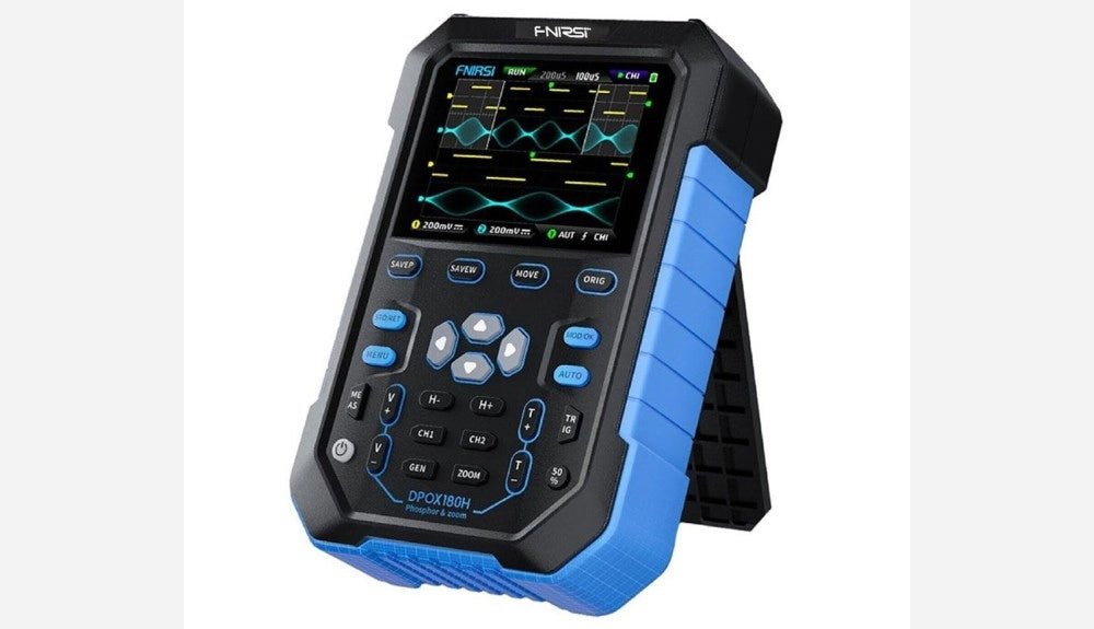
FNIRSI DPOX180H 2-in-1 Digital Phosphor Oscilloscope (Review)
Oscilloscopes sure have made a lot of progress over the past two decades. Twenty years ago, I still used my single-beam analog 20 MHz CRT oscilloscope...