Search results for "proton"
-
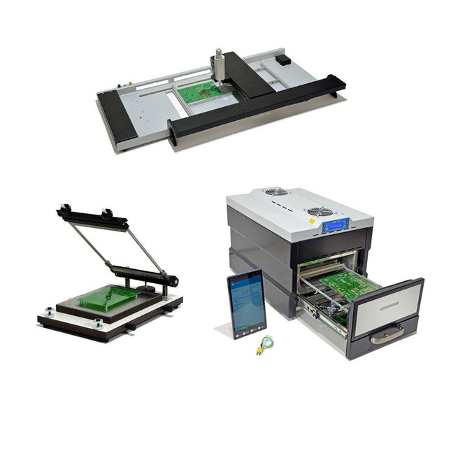
Paggen Werkzeugtechnik SMD Starter I – Production Line for Prototypes
The SMD Starter I prototype production line consists of the stencil printer TSD240, the SMD placement device PlaceMAN and the reflow oven 3LHR10. Stencil printer SD240 (+ Metal Squeegee 155 mm) Stencil size: max. 175 x 255 mm PCB size: max. 180 x 240 mm Size: 410 x 270 x 110 mm Weight: 6.7 kg incl. metal squeegee 155 mm incl. 8 magnets to hold the PCB, 6 of them with M3 grub screw Manual SMD pick-and-place device PlaceMAN for standard components incl. vacuum pump (without feeders, camera, monitor and dispenser) Equipped with smooth-running placement arm, placement head with one-hand operation, rotation of the Z-axis and automatic vacuum switch-off, incl. PCB holder, vacuum unit and 2 placement needles with rubber suction cups. Capacity of feeder (not included) 2x feeder cassette for 10 x 8 mm wheels left 4x feeder cassette for rod feeders for 5 rods each Further feeding systems are possible within the assembly area, e.g. strip-feeder plug-in system Dimensions Base unit (LxWxH): 765 x 390 x 210 mm With feeder cassette for 10 x 8 mm rolls (LxWxH): 765 x 390 x 210 mm With feeder cassette for 10 x 8 mm rolls and feeder cassette for rod feeder (LxWxH): 765 x 430 x 210 mm (height may vary due to rod length) With feeder cassette for 10 x 8 mm rolls incl. holder for 10 rolls and feeder cassette for rod feeder (LxWxH): 765 x 430 x 210 mm (height may vary due to rod length) Specifications Weight of basic unit: approx. 6 kg Axis travel (x,y,z): 470 x 230 x 15 mm Max. working area: 380 x 240 mm Max. PCB size: 230 x 360 mm Power supply: 230/12 V, 800 mA Power supply vacuum pump: 230 V, 6 W 3LHR10 Reflow Oven (programmable for lead-free soldering with manual drawer and tablet control) Reflow oven with IR and convection heating. Forced hot air convection ensures a uniform temperature profile throughout the chamber. After manually opening the door, the fans are turned on and the soldered PCB is quickly cooled. Small reflow oven with manual door Industry 4.0 ready, Bluetooth communication + tablet IR + convection heating Android application to connect to tablet or smartphone 100 different user programs Delivery content: 3LHR10, tablet with app, protective cover for tablet, 4 PCB holders, external thermocouple, manual at tablet Application Connect the oven to the power supply and connect the optionally available extraction system (3LFE10S) to the exhaust air nozzle. After the first turn on, the oven will search for a tablet or smartphone. When both are connected to the Android app, choose the programming of the oven. Here, programmable temperature and preheating time as well as temperature and other data are to be set. Register with the tablet to use the full scope of the software. If the oven is already programmed, the user can control the operation with buttons and display at the front panel. When the reflow process is complete, an audible signal sounds. A signal is also displayed on the tablet/smartphone. The drawer must now be opened manually. The Android application displays process status, time and temperature or other information. Specifications Power supply: 230 V, 50 Hz Maximum power: 3100 W Temperatures: 50-260°C Dimensions: 510 x 370 x 340 mm Maximum weight: 16 kg Grid dimensions: 350 x 220 mm Maximum dimensions of the printed circuit board: 300 x 200 mm Maximum component height on the PCB: 50 mm at the top, 30 mm at the bottom Scope of delivery Stencil printer TSD240 SMD placement device PlaceMAN Reflow oven 3LHR10
€ 6.549,00
Best Price
-
Elektor Digital Python 3 Programming and GUIs (E-book)
This is the second edition of a book aimed at engineers, scientists, and hobbyists who want to interface PCs with hardware projects using graphical user interfaces. Desktop and web-based applications are covered. The programming language used is Python 3, which is one of the most popular languages around: speed of programming being a key feature. The book has been revised and updated with an emphasis on getting the user to produce practical designs with ease – a text editor is all that is required to produce Python programs. Hardware interfacing is achieved using an Arduino Uno as a remote slave. A full description and source code of the communication interface is given in the book. The slave provides digital and analog input and outputs. Multiple Unos can be included in one project with all control code written in Python and running on a PC One project involves a PIC microcontroller with the code provided that can be loaded into the PIC using the Uno. The web applications and server are all implemented in Python, allowing you to access your electronic hardware over the Internet. The Raspberry Pi computer can be used as your web server. An introductory chapter is provided to get you started with using Linux. The book is written for use with Debian or variations including Mint or Ubuntu. All of the programs in the book are freely available, ready to use and experiment with by way of a download from Elektor.
€ 29,95
Members: € 23,96
-
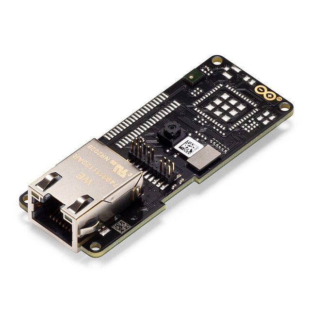
Arduino Arduino Pro Portenta Vision Shield (Ethernet)
The Arduino Pro Portenta Vision Shield brings industry-rated features to your Portenta. This hardware add-on will let you run embedded computer vision applications, connect wirelessly or via Ethernet to the Arduino Cloud or your own infrastructure, and activate your system upon the detection of sound events. Features 324x324 pixels camera sensor: use one of the cores in Portenta to run image recognition algorithms using the OpenMV for Arduino editor 100 Mbps Ethernet connector: get your Portenta H7 connected to the wired Internet 2 onboard microphones for directional sound detection: capture and analyse sound in real-time JTAG connector: perform low-level debugging of your Portenta board or special firmware updates using an external programmer SD-Card connector: store your captured data in the card, or read configuration files The Vision Shield has been designed to fit on top of the Arduino Portenta family. The Portenta boards feature multicore 32-bit ARM Cortex processors running at hundreds of megahertz, with megabytes of program memory and RAM. Portenta boards come with WiFi and Bluetooth. Embedded Computer Vision Made Easy Arduino has teamed up with OpenMV to offer you a free license to the OpenMV IDE, an easy way into computer vision using MicroPython as a programming paradigm. Download the OpenMV for Arduino Editor from our professional tutorials site and browse through the examples we have prepared for you inside the OpenMV IDE. Companies across the whole world are already building their commercial products based on this simple-yet-powerful approach to detect, filter, and classify images, QR codes, and others. Debugging With Professional Tools Connect your Portenta H7 to a professional debugger through the JTAG connector. Use professional software tools like the ones from Lauterbach or Segger on top of your board to debug your code step by step. The Vision Shield exposes the required pins for you to plug in your external JTAG. Camera Himax HM-01B0 camera module Resolution 320 x 320 active pixel resolution with support for QVGA Image sensor High sensitivity 3.6μ BrightSense pixel technology Microphone 2 x MP34DT05 Length 66 mm Width 25 mm Weight 11 gr For more information, check out the tutorials provided by Arduino here.
€ 69,95€ 19,95
Best Price
-
Elektor Digital Elektor Arduino Guest Edition 2022 (PDF) EN
Elektor GREEN and GOLD members can download their digital edition here. Not a member yet? Click here. Arduino Portenta Machine Control and Arduino Portenta H7A CAN-to-MQTT Gateway Demo Project Unboxing the Elektor LCR Meter with David Cuartielles MicroPython Enters the World of Arduino Connected Projects, SimplifiedDive Into the Arduino Cloud Introduction to TinyMLBig Is Not Always Better Arduino K-Way Writing Arduino Sketches Just Got Better Get to Know Arduino Getting Started with the Portenta X8Manage Software Securely with Containers Build, Deploy, and Maintain Scalable, Secure ApplicationsWith Arduino Portenta X8 Featuring NXP’s i.MX 8M Mini Applications Processor and EdgeLock SE050 Secure Element How I Automated My HomeArduino CEO Fabio Violante Shares Solutions Altair 8800 SimulatorHardware Simulation of a Vintage Computer MS-DOS on the Portenta H7Run Old-School Software on Contemporary Hardware Grow It YourselfA Digitally Controlled, Single-Box Solution for Indoor Farming Save the Planet With Home Automation?MQTT on the Arduino Nano RP2040 Connect Go Professional with Arduino Pro Smart Ovens Take a Leap Into the Future Tagvance Builds Safer Construction Sites with Arduino Santagostino Breathes Easywith Remote Monitoring that Leverages AI for Predictive Maintenance Security Flies High with RIoT Secure’s MKR-Based Solution Open-Source Brings a New Generation of Water Management to the World SensoDetect Deforestation with Sound Analysis The Mozzi Arduino Library for Sound SynthesisInsights from Tim Barrass The New Portenta X8 (with Linux!) and Max Carrier Redefine What’s Possible How Using Arduino Helps Students Build Future Skills Must-Haves for Your Electronics Workspace The Importance of Robotics in Education Dependable IoT Based Upon LoRa Unboxing the Portenta Machine Control 8-Bit Gaming with Arduboy Reducing Water Usage at Horseback Riding TracksAn IoT to Constantly Monitor Soil Humidity and Temperature Levels The Panettone ProjectA sourdough starter management and maintenance system Supporting Arduino Resellers Space Invaders with Arduino Art with ArduinoInspiring Insights from Artists and Designers Arduino Product Catalogue The Future of Arduino
€ 7,50
-

Elektor Digital Practical Microcontroller Cryptography (E-book)
From Simple Ciphers to Secure Systems Understanding how to apply cryptography on modern microcontrollers is essential for building secure, reliable, and trustworthy systems. This book explains cryptography in the context of embedded hardware, from classical ciphers that illustrate core principles to modern techniques such as AES for practical high-security applications. By combining mathematical theory with real-world microcontroller implementations, readers learn not only how cryptography works, but also how to implement it effectively on systems with limited processing power and memory. The book is intended for students starting out in cryptography, hobbyists securing personal projects, and engineers looking for a structured guide to embedded security. The book covers these key topics in applied cryptography: Classical ciphers on Arduino Uno and Raspberry Pi Pico, with full programs: Spartan Scytale, Hebrew Atbash, Caesar, ROT13, Alberti Disk, Vigenère, Affine, Polybius, Playfair, Beaufort, Ottoman Codebook, and One-Time Pad. Hacking classical ciphers using microcontrollers, with examples. Pseudo-random (PRNG) and true random number generation (TRNG) on microcontrollers. Symmetric-key cryptography with full programs: DES and AES-128/256. Memory and speed constraints of cryptography on microcontrollers. Asymmetric cryptography: public/private keys, digital signatures, key distribution and derivation (KDF), RSA, and SHA-256 implementations. A complete secure communication program using RSA and AES-256. A glossary of commonly used cryptography terms.
€ 29,95
Members: € 23,96
-

Elektor Digital Elektor March/April 2022 (PDF)
Build Your Own RISC-V ControllerFirst Steps with the NEORV32 RISC-V Softcore for Low-Cost FPGAs How to Use Arduino’s Serial PlotterPlotting Graphs With Arduino Is Easy CLUE from AdafruitA Smart Solution for IoT Projects Buffer Board for the Raspberry Pi 400Protect the I/Os Raspberry Pi RP2040 Boards Aplenty A Handbook on DIY Electronic Security and EspionageSRAM Heated or Deep-Frozen Component IdentificationTips & Tricks, Best Practices and Other Useful Information DIY Touchless Light Switch Starting out in ElectronicsMatching and Transforming What’s New in Embedded Development?Rust and Keeping IoT Deployments Updated Infographics How the Industrial and Automotive Sectors Will Benefit from 5G Moving Coil RelaysPeculiar Parts, the series HomeLab ToursEverything Revolves Around the Tools... Understanding the Neurons in Neural Networks (Part 4)Embedded Neurons Magnetic Levitation the Very Easy WayThe Third and Most Compact Version PLC Programming with the Raspberry Pi and the OpenPLC ProjectVisualization of PLC Programs with AdvancedHMI From Life's ExperiencePack Up and Leave Under Your RadarMicrocontrollers You Should Know About Monitor and Debug Over the AirA Solution for Arduino, ESP32 and Co. Portable Temperature- and Humidity-Measuring DeviceUsing Ready-Made Modules Lithium Battery Pack RepairSave Money + More Power! GUIs with PythonMeme-Generator Three Questions to Build OnWhy, What, and Who? HexadokuThe Original Elektorized Sudoku
€ 7,50
-

Elektor May/June 2026 (EN)
Elektor GREEN and GOLD members can download their digital edition here. Not a member yet? Click here. PbMonitor v2.0 UpdateBattery Monitoring with Improved Analog Design Audio Latency MeasurementA Standalone Tool for Evaluating Errors and Latency in Audio Transmission Square Wave vs. Bode PlotChecking the Performances of an Audio Device embedded world 2026 Clever Coding with AIAI in Software Development for Electronics Engineers QA403 Audio AnalyzerAffordable Precision for Audio Professionals and Hobbyists EasyGimbalAutonomous Camera Tracking with AI, Stepper and Servo Motors Sigfox Breakout Board (2)Sending Messages Circuit ProtectionControlling Overvoltages with TVS Diodes Emerging Battery Testing ApproachesA New Era of Diagnostics AudiotronicsA First Preamplifier CANopenTermAn Open-Source Tool That Brings CAN to Makers and Engineers Alike Stabilization of Operational AmplifiersAvoiding Feedback Instability Err-lectronicsCorrections, Updates, and Readers’ Letters Signal ConditioningTips and Tricks to Fit Voltage Ranges TDR Attachment for OscilloscopesLength, Short Circuit, Mismatch: Measure Cables Using Reflections! From Life's ExperienceLED It Be Speaker Oscillator and Resonance TesterA Fully Experimental Project for Your Speakers Elektor Community Perspectives on Test and Measurement ESP32 Audio Transceiver Board (Part 5)Audio Processing and Remote Control 2026: An AI OdysseyAI Has a Context Problem Battery Storage for Balcony Power PlantsSmall Batteries, Big Impact
€ 14,90
-

Elektor Digital Elektor March/April 2026 (PDF) EN
Elektor GREEN and GOLD members can download their digital edition here. Not a member yet? Click here. PIO Programming on the Raspberry Pi PicoNine Instructions, Many Possibilities Breaking AI Out of the BrowserUsing AI CLIs to Code, Compile, and Validate Embedded Projects The Scrutiny DebuggerDebug, Visualize, and Test Embedded C/C++ Code Sigfox Breakout Board (1)A Self-Built Radio BoB Low-Noise Power Supply (2)Construction, Assembly, and Practical Implementation Simple Signal Generator Using the RP2040Analog and Digital Signals for Around €10 Navigating the Future of Smart Homes with Matter and Edge AIAre Matter’s Latest Updates and the Rise of Edge AI Finally Giving Engineers the Tools to Build the Intelligent, Seamless Smart Homes Users Have Been Promised? Differential Pressure SensorsPredictive Maintenance in HVAC-Systems Security by DesignEngineering Fundamentals Limit Failure Embedded Security Is No Longer Optional CRA and PQC Are Rewriting Embedded Security PrioritiesWhy Even Small IoT and Industrial Firms Need an Upgrade Plan embedded world 2026An Interview With Benedikt Weyerer, Executive Director of embedded world Hands on with I3CUsing Hardware from ST and Microchip The BLEnky ProjectRapid Prototyping of Bluetooth Low Energy Applications Pulse Width ModulationFrom a Simple On/Off Thermostat to a Smoothed DC Analog Signal AudiotronicsEar-Pleasing Electronics for DIY Construction From Life’s ExperienceRead The F...ing Manual! ESP32 Audio Transceiver Board (Part 4)Tuning the Clocks - And a Wired Option 2026: An AI OdysseyThe 2025 Vibe-Coding Hangover Symmetrical DC LoadDC Load, Static or Dynamic, and Symmetrical Counting Faces with MaixCAMAn Easy Way to Capture Audience Sizes
€ 9,50
-

Elektor Publishing Experimenting with Red Pitaya STEMlab Gen 2
Practical Projects and Programs With Experimenting with Red Pitaya STEMlab Gen 2, Red Pitaya goes beyond a versatile board. It becomes a powerful laboratory instrument for precision measurement, analysis, and control. From the fundamentals of electronic project development, monitoring, control, and design to testing, this book walks you step-by-step through everything you need to know to harness the full potential of Red Pitaya hardware and software. The book presents real-time, FPGA-based projects that are developed on a PC using the Vivado environment, then transferred to the Red Pitaya for execution and testing. You will learn about enhanced performance, expanded I/O capabilities, improved FPGA features, and advanced connectivity options that open up new frontiers for precision measurement, monitoring, and control in your embedded applications. Inside the book you will discover: A deep dive into Red Pitaya architecture and hardware design Electronic experiments using Red Pitaya for measurement and monitoring Hands-on projects using the Python programming language Practical guidance for FPGA programming using Red Pitaya Red Pitaya FPGA projects using the Verilog HDL under Vivado IDE Practical design of electronic projects including measurement and testing Step-by-step examples that bridge theory and real-world implementation Whether you are designing your own electronic circuits, developing signal analysis tools, or creating real-time control or monitoring systems, this book provides you the knowledge and confidence you need to fully learn and customize the Red Pitaya platform.
€ 39,95€ 32,95
Best Price
-

Elektor Digital Experimenting with Red Pitaya STEMlab Gen 2 (E-book)
Practical Projects and Programs With Experimenting with Red Pitaya STEMlab Gen 2, Red Pitaya goes beyond a versatile board. It becomes a powerful laboratory instrument for precision measurement, analysis, and control. From the fundamentals of electronic project development, monitoring, control, and design to testing, this book walks you step-by-step through everything you need to know to harness the full potential of Red Pitaya hardware and software. The book presents real-time, FPGA-based projects that are developed on a PC using the Vivado environment, then transferred to the Red Pitaya for execution and testing. You will learn about enhanced performance, expanded I/O capabilities, improved FPGA features, and advanced connectivity options that open up new frontiers for precision measurement, monitoring, and control in your embedded applications. Inside the book you will discover: A deep dive into Red Pitaya architecture and hardware design Electronic experiments using Red Pitaya for measurement and monitoring Hands-on projects using the Python programming language Practical guidance for FPGA programming using Red Pitaya Red Pitaya FPGA projects using the Verilog HDL under Vivado IDE Practical design of electronic projects including measurement and testing Step-by-step examples that bridge theory and real-world implementation Whether you are designing your own electronic circuits, developing signal analysis tools, or creating real-time control or monitoring systems, this book provides you the knowledge and confidence you need to fully learn and customize the Red Pitaya platform.
€ 32,95
Members: € 26,36
-

Elektor March/April 2026 (EN)
Elektor GREEN and GOLD members can download their digital edition here. Not a member yet? Click here. PIO Programming on the Raspberry Pi PicoNine Instructions, Many Possibilities Breaking AI Out of the BrowserUsing AI CLIs to Code, Compile, and Validate Embedded Projects The Scrutiny DebuggerDebug, Visualize, and Test Embedded C/C++ Code Sigfox Breakout Board (1)A Self-Built Radio BoB Low-Noise Power Supply (2)Construction, Assembly, and Practical Implementation Simple Signal Generator Using the RP2040Analog and Digital Signals for Around €10 Navigating the Future of Smart Homes with Matter and Edge AIAre Matter’s Latest Updates and the Rise of Edge AI Finally Giving Engineers the Tools to Build the Intelligent, Seamless Smart Homes Users Have Been Promised? Differential Pressure SensorsPredictive Maintenance in HVAC-Systems Security by DesignEngineering Fundamentals Limit Failure Embedded Security Is No Longer Optional CRA and PQC Are Rewriting Embedded Security PrioritiesWhy Even Small IoT and Industrial Firms Need an Upgrade Plan embedded world 2026An Interview With Benedikt Weyerer, Executive Director of embedded world Hands on with I3CUsing Hardware from ST and Microchip The BLEnky ProjectRapid Prototyping of Bluetooth Low Energy Applications Pulse Width ModulationFrom a Simple On/Off Thermostat to a Smoothed DC Analog Signal AudiotronicsEar-Pleasing Electronics for DIY Construction From Life’s ExperienceRead The F...ing Manual! ESP32 Audio Transceiver Board (Part 4)Tuning the Clocks - And a Wired Option 2026: An AI OdysseyThe 2025 Vibe-Coding Hangover Symmetrical DC LoadDC Load, Static or Dynamic, and Symmetrical Counting Faces with MaixCAMAn Easy Way to Capture Audience Sizes
€ 14,90
-

Elektor Digital Elektor May/June 2026 (PDF) EN
Elektor GREEN and GOLD members can download their digital edition here. Not a member yet? Click here. PbMonitor v2.0 UpdateBattery Monitoring with Improved Analog Design Audio Latency MeasurementA Standalone Tool for Evaluating Errors and Latency in Audio Transmission Square Wave vs. Bode PlotChecking the Performances of an Audio Device embedded world 2026 Clever Coding with AIAI in Software Development for Electronics Engineers QA403 Audio AnalyzerAffordable Precision for Audio Professionals and Hobbyists EasyGimbalAutonomous Camera Tracking with AI, Stepper and Servo Motors Sigfox Breakout Board (2)Sending Messages Circuit ProtectionControlling Overvoltages with TVS Diodes Emerging Battery Testing ApproachesA New Era of Diagnostics AudiotronicsA First Preamplifier CANopenTermAn Open-Source Tool That Brings CAN to Makers and Engineers Alike Stabilization of Operational AmplifiersAvoiding Feedback Instability Err-lectronicsCorrections, Updates, and Readers’ Letters Signal ConditioningTips and Tricks to Fit Voltage Ranges TDR Attachment for OscilloscopesLength, Short Circuit, Mismatch: Measure Cables Using Reflections! From Life's ExperienceLED It Be Speaker Oscillator and Resonance TesterA Fully Experimental Project for Your Speakers Elektor Community Perspectives on Test and Measurement ESP32 Audio Transceiver Board (Part 5)Audio Processing and Remote Control 2026: An AI OdysseyAI Has a Context Problem Battery Storage for Balcony Power PlantsSmall Batteries, Big Impact
€ 9,50


