Search results for "multi OR purpose OR gps OR receiver OR pcb OR 3964"
-
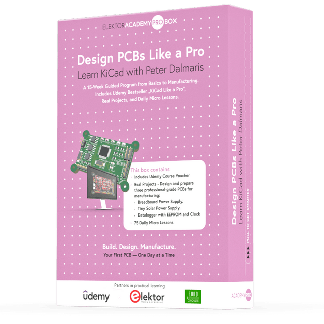
Elektor Academy Pro Design PCBs Like a Pro
Learn KiCad with Peter Dalmaris The Academy Pro Box "Design PCBs like a Pro" offers a complete, structured training programme in PCB design, combining online learning with practical application. Based on Peter Dalmaris’ KiCad course, the 15-week programme integrates video lessons, printed materials (2 books), and hands-on projects to ensure participants not only understand the theory but also develop the skills to apply it in practice. Unlike standard courses, the Academy Pro Box provides a guided learning path with weekly milestones and physical components to design, test, and produce working PCBs. This approach supports a deeper learning experience and better knowledge retention. The box is ideal for engineers, students, and professionals who want to develop practical PCB design expertise using open-source tools. With the added option to have their final project manufactured, participants complete the programme with real results – ready for use, testing, or further development. Learn by doing Build skills. Design real boards. Generate Gerbers. Place your first order. This isn’t just a course – it’s a complete project journey from idea to product. You’ll walk away with: Working knowledge of KiCad’s tools Confidence designing your own PCBs A fully manufacturable circuit board – made by you What's inside the Box (Course)? Both volumes of "KiCad Like a Pro" (valued at €105) Vol 1: Fundamentals and Projects Vol 2: Advanced Projects and Recipes Coupon code to join the bestselling KiCad 9 online course by Peter Dalmaris on Udemy, featuring 20+ hours of video training. You'll complete three full design projects: Breadboard Power Supply Tiny Solar Power Supply Datalogger with EEPROM and Clock Voucher from Eurocircuits for the production of PCBs (worth €85 excl. VAT) Learning Material (of this Box/Course) 15-Week Learning Program ▶ Click here to open Week 1: Setup, Fundamentals, and First Steps in PCB Design Week 2: Starting Your First PCB Project – Schematic Capture Week 3: PCB Layout – From Netlist to Board Design Week 4: Design Principles, Libraries, and Workflow Week 5: Your First Real-World PCB Project Week 6: Custom Libraries – Symbols, Footprints, and Workflow Week 7: Advanced Tools – Net Classes, Rules, Zones, Routing Week 8: Manufacturing Files, BOMs, and PCB Ordering Week 9: Advanced Finishing Techniques – Graphics, Refinement, and Production Quality Week 10: Tiny Solar Power Supply – From Schematic to Layout Week 11: Tiny Solar Power Supply – PCB Layout and Production Prep Week 12: ESP32 Clone Project – Schematic Design and Layout Prep Week 13: ESP32 Clone – PCB Layout and Manufacturing Prep Week 14: Final Improvements and Advanced Features Week 15: Productivity Tools, Simulation, and Automation KiCad Course with 18 Lessons on Udemy (by Peter Dalmaris) ▶ Click here to open Introduction Getting started with PCB design Getting started with KiCad Project: A hands-on tour of KiCad (Schematic Design) Project: A hands-on tour of KiCad (Layout) Design principles and PCB terms Design workflow and considerations Fundamental KiCad how-to: Symbols and Eeschema Fundamental KiCad how-to: Footprints and Pcbnew Project: Design a simple breadboard power supply PCB Project: Tiny Solar Power Supply Project: MCU datalogger with build-in 512K EEPROM and clock Recipes KiCad 9 new features and improvements Legacy (from previous versions of KiCad) KiCad 7 update (Legacy) (Legacy) Gettings started with KiCad Bonus lecture About the Author Dr. Peter Dalmaris, PhD is an educator, an electrical engineer and Maker. Creator of online video courses on DIY electronics and author of several technical books. As a Chief Tech Explorer since 2013 at Tech Explorations, the company he founded in Sydney, Australia, Peter's mission is to explore technology and help educate the world. What is Elektor Academy Pro? Elektor Academy Pro delivers specialized learning solutions designed for professionals, engineering teams, and technical experts in the electronics and embedded systems industry. It enables individuals and organizations to expand their practical knowledge, enhance their skills, and stay ahead of the curve through high-quality resources and hands-on training tools. From real-world projects and expert-led courses to in-depth technical insights, Elektor empowers engineers to tackle today’s electronics and embedded systems challenges. Our educational offerings include Academy Books, Pro Boxes, Webinars, Conferences, and industry-focused B2B magazines – all created with professional development in mind. Whether you're an engineer, R&D specialist, or technical decision-maker, Elektor Academy Pro bridges the gap between theory and practice, helping you master emerging technologies and drive innovation within your organization.
€ 199,95€ 164,95
Best Price
-
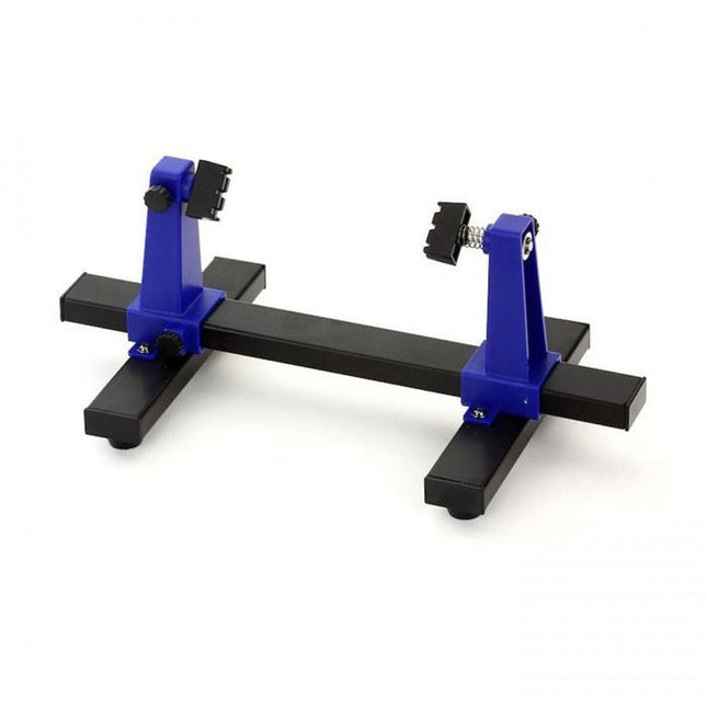
Zhongdi ZD-11E PCB Holder
This adjustable circuit board holder is ideal for clamping PCB for soldering, desoldering or rework. Features 2 adjustable grips on a retractable stand to accommodate various board sizes. The adjustable clamps allow the PCB to rotate 360 degrees and stay set in any position. The base of this rigid metal stand features four rubber feet to ensure stability. Specifications Product size 30 x 16.5 x 12.5 cm Max. holding size 20 x 14 cm Weight 450 g
€ 7,95
-
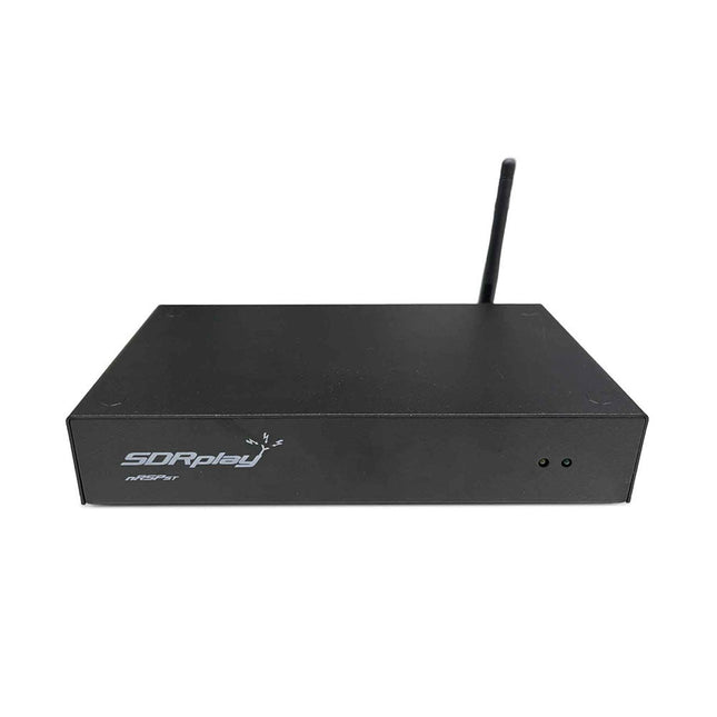
SDRplay SDRplay nRSP-ST Networked Radio Receiver (1 kHz to 2 GHz)
The nRSP-ST is a networked general coverage radio receiver for frequencies from 1 kHz to 2 GHz with up to 10 MHz of spectrum visibility. The nRSP-ST is your own personal remotely accessible SDR which can also be shared with a small number of trusted friends or colleagues. The nRSP-ST addresses the needs of radio enthusiasts who want a 'plug-and-play' solution for remote reception. As well as achieving this, we have addressed typical internet bandwidth limitations with the creation of a novel IQ Lite mode, which efficiently delivers channels of IQ data. We are also introducing the ability to control and store IQ recordings at the remote location. The nRSP-ST is ideal for anyone wanting a wideband remote receiver without needing computer skills and hours of set-up time and ongoing maintenance at the remote location. Features "Plug and play" integrated, networked general coverage receiver: Combines a receiver, a host computer and a whole lot more – all in one box! Apply power and connect to the internet (Ethernet or Wi-Fi) and the nRSP-ST is automatically accessible from anywhere Multi-platform SDRconnectTM software supports local operation or remote access on Windows, MacOS or Linux platforms The nRSP-ST & SDRconnect are configurable for available network bandwidth: In Full IQ mode, the nRSP-ST provides IQ data transfer of the visible spectrum bandwidth (e.g. for high-speed LAN or superfast internet connectivity) In IQ Lite mode, the nRSP-ST provides IQ data of channels up to 192 kHz wide (e.g. for digital decoding by the client) In Compact mode the nRSP-ST provides compressed audio (ideal for slower internet connections) Supports multiple client connections with a simultaneous mixture of connection modes – an admin tool allows you to assign usernames and timeouts to trusted friends or colleagues. All modes support visualization of up to 10 MHz spectrum bandwidth Two remote connection options: Use a remote SDRconnect client or Use the built-in web-server for remote access from any web browsing capable device, including Android/iOS tablets and phones The nRSP-ST offers the ability to record IQ and audio files to a NAS (network attached storage) device if available on the LAN. The 14-bit ADC full featured wideband SDR receiver covers all frequencies from 1 kHz through VLF, LF, MW, HF, VHF, UHF and L-band to 2 GHz, with no gaps Remotely monitor up to 10 MHz of spectrum at a time from a choice of 3 antennas Flash upgradable for future feature enhancements Included 1x nRSP-ST Receiver 1x WLAN antenna 1x Power supply 1x Manual Downloads Release notes Software
€ 554,18
-

SDRplay SDRplay RSP1B 14-bit SDR Receiver (1 kHz to 2 GHz)
The SDRplay RSP1B is an enhanced version of the popular RSP1A – a powerful, wideband, full-featured 14-bit SDR that covers the RF spectrum from 1 kHz to 2 GHz. The RSP1B comes in a rugged, black-painted steel case and offers significantly improved noise performance. All it needs is a computer and an antenna to deliver excellent communications-receiver functionality. It includes a choice of SDRuno for Windows and the multi-platform SDRconnect software for Windows, macOS, and Linux (supplied free of charge by SDRplay). You can monitor up to 10 MHz of spectrum at a time. A documented API allows developers to create new demodulators or applications for the platform. Features Covers all frequencies from 1 kHz through VLF, LF, MW, HF, VHF, UHF and L-band to 2 GHz, with no gaps Receive, monitor and record up to 10 MHz of spectrum at a time Free use of windows-based SDRuno software which provides an ever-increasing feature-set Strong and growing software support network Calibrated S meter/ RF power and SNR measurement with SDRuno (including datalogging to .CSV file capability) Documented API provided to allow demodulator or application development on multiple platforms Excellent dynamic range for challenging reception conditions Works with popular 3rd party SDR software (including HDSDR, SDR Console and Cubic SDR) ExtIO based plugin available Software upgradeable for future standards Strong and growing software support network API provided to allow demodulator or application development Multiplatform driver and API support including Windows, Linux, Mac, Android and Raspberry Pi Up to 16 individual receivers in any 10 MHz slice of spectrum using SDRuno Calibrated S meter and power measurements with SDRuno Stand-alone windows-based spectrum analyser software available (with sweep, sample and hold features) Ideal for monitoring of ISM/ IoT/ Telemetry bands <2 GHz Ideal for portable operation Specifications Frequency Range 1 kHz – 2 GHz Antenna Connector SMA Antenna Impedance 50 Ohms Current Consumption (Typical) 185 mA (excl. Bias-T) USB Connector USB Type B Maximum Input Power +0 dBm Continuous+10 dBm Short Duration ADC Sample Rates 2-10.66 MSPS ADC Number of Bits 14 bit 2-6.048 MSPS12 bit 6.048-8.064 MSPS10 bit 8.064-9.216 MSPS8 bit >9.216 MSPS Bias-T 4.7 V100 mA guaranteed Reference 0.5ppm 24 MHz TCXO.Frequency error trimmable to 0.01ppm in field. Operating Temperature Range -10˚C to +60˚C Dimensions 98 x 88 x 34 mm Weight 110 g Downloads Datasheet Software RSP1B vs RSPdx vs RSPduo RSP1B RSPdx RSPduo Continuous coverage from 1 kHz to 2 GHz ✓ ✓ ✓ Up to 10 Mhz visible bandwidth ✓ ✓ ✓ 14-bit ADC silicon technology plus multiple high-performance input filters ✓ ✓ ✓ Software selectable AM/FM & DAB broadcast band notch filters ✓ ✓ ✓ 4.7 V Bias-T for powering external remote antenna amplifier ✓ ✓ ✓ Powers over the USB cable with a simple type B socket ✓ ✓ ✓ 50Ω SMA antenna input(s) for 1 kHz to 2 GHz operation (software selectable) 1 2 2 Additional software selectable Hi-Z input for up to 30 Mhz operation ✓ Additional software selectable 50Ω BNC input for up to 200 MHz operation ✓ Additional LF/VLF filter for below 500 kHz ✓ 24 MHz reference clock input (+ output on RSPduo) ✓ ✓ Dual tuners enabling reception on 2 totally independent 2 MHz ranges ✓ Dual tuners enabling diversity reception using SDRuno ✓ Robust and strong plastic case (with internal RF shielding layer) ✓ Rugged black painted steel case ✓ ✓ Overall performance below 2 MHz for MW and LF + ++ + Multiple simultaneous applications + + ++ Performance in challenging fading conditions (*using diversity tuning) + + *++
€ 148,99
-
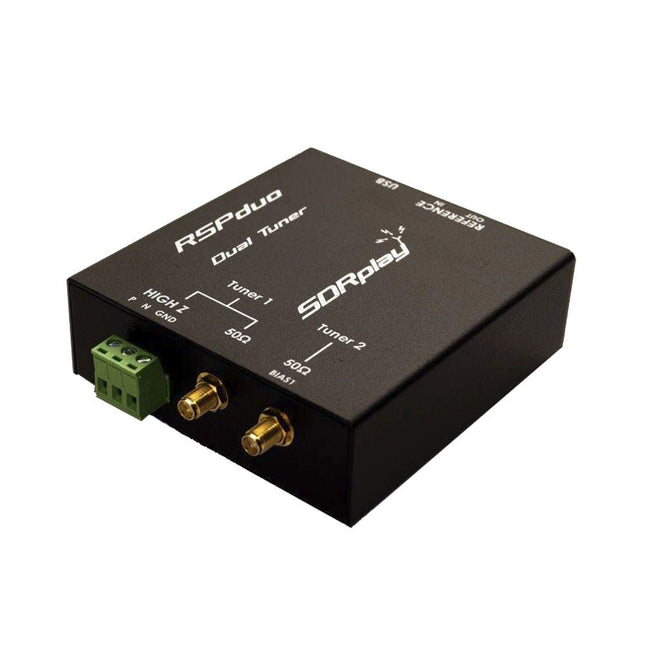
SDRplay SDRplay RSPduo Dual-Tuner 14-bit SDR Receiver (1 kHz to 2 GHz)
The SDRplay RSPduo is a high performance dual-tuner 14-bit SDR receiver. Housed in a high quality steel enclosure, each tuner can operate individually anywhere between 1 kHz and 2 GHz with up to 10 MHz of bandwidth or both tuners can operate simultaneously anywhere between 1 kHz and 2 GHz with up to 2 MHz of bandwidth per tuner. A high stability reference along with external clocking features makes this device ideally suited to industrial, scientific & educational applications. Features Dual tuner provides independent coverage from 1 kHz to 2 GHz using 2 antenna ports simultaneously 14-bit ADC silicon technology Up to 10 MHz visible bandwidth (single tuner mode) or 2 slices of 2 MHz spectrum (dual tuner mode) 3 software-selectable antenna ports (2x 50Ω and 1x 1kΩ high impedance balanced/unbalanced input) High impedance antenna port (1 kHz to 30 MHz) with selectable MW notch filter and choice of 2 pre-selection filters Software selectable AM/FM and DAB broadcast band notch filters for the 2 SMA antenna (1 kHz to 2 GHz) antenna ports External clock input and output enables easy synchronisation to multiple RSPs or external reference clock Powers over the USB cable with a simple type B socket 11 high-selectivity, built in front-end preselection filters on both the 2 SMA antenna ports Software selectable multi-level Low Noise Preamplifier Bias-T power supply for powering antenna-mounted LNA Enclosed in a rugged black painted steel case. SDRuno – World Class SDR software for Windows Documented API for new apps development Specifications Frequency Range 1 kHz – 2 GHz Antenna Connector SMA Antenna Impedance 50 Ohms Current Consumption (Typical) Single Tuner Mode: 180 mA (excl. Bias-T)Dual Tuner Mode: 280 mA (excl. Bias-T) USB Connector USB-B Maximum Input Power +0 dBm Continuous+10 dBm Short Duration ADC Sample Rates 2-10.66 MSPS ADC Number of Bits 14 bit 2-6.048 MSPS12 bit 6.048-8.064 MSPS10 bit 8.064-9.216 MSPS8 bit >9.216 MSPS Bias-T 4.7 V100 mA guaranteed Reference High Temperature Stability (0.5ppm) 24 MHz TCXO.Frequency error trimmable to 0.01ppm in field. Operating Temperature Range −10˚C to +60˚C Dimensions 98 x 94 x 33 mm Weight 315 g Downloads Datasheet Detailed Technical Information Software RSPdx-R2 vs RSPduo RSPdx-R2 RSPduo Continuous coverage from 1 kHz to 2 GHz ✓ ✓ Up to 10 MHz visible bandwidth ✓ ✓ 14-bit ADC silicon technology plus multiple high-performance input filters ✓ ✓ Software selectable AM/FM & DAB broadcast band notch filters ✓ ✓ 4.7 V Bias-T for powering external remote antenna amplifier ✓ ✓ Powers over the USB cable with a simple type B socket ✓ ✓ 50Ω SMA antenna input(s) for 1 kHz to 2 GHz operation (software selectable) 2 2 Additional software selectable Hi-Z input for up to 30 Mhz operation ✓ Additional software selectable 50Ω BNC input for up to 200 MHz operation ✓ Additional LF/VLF filter for below 500 kHz ✓ 24 MHz reference clock input (+ output on RSPduo) ✓ ✓ Dual tuners enabling reception on 2 totally independent 2 MHz ranges ✓ Dual tuners enabling diversity reception using SDRuno ✓ Rugged black painted steel case ✓ ✓ Overall performance below 2 MHz for MW and LF ++ + Multiple simultaneous applications + ++ Performance in challenging fading conditions (*using diversity tuning) + *++
€ 287,98
-
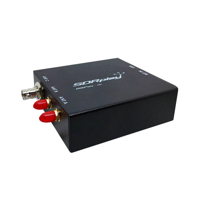
SDRplay SDRplay RSPdx-R2 Single-Tuner 14-bit SDR Receiver (1 kHz to 2 GHz)
The SDRplay RSPdx-R2 is a wideband full featured single-tuner 14-bit SDR receiver which covers the entire RF spectrum from 1 kHz to 2 GHz giving up to 10 MHz of spectrum visibility. It contains three antenna ports, two of which use SMA connectors and operate across the full 1 kHz to 2 GHz range and the third uses a BNC connector which operates up to 200 MHz. The RSPdx-R2 is an enhanced version of the RSPdx with further design improvements for use at frequencies below 2 MHz. Housed in a strong steel case, in addition to the functionality of the RSP1B, the RSPdx-R2 provides three software selectable antenna inputs and an external clock input. It offers excellent performance through HF and VHF frequencies all the way up to 2 GHz. The RSPdx-R2 also supports an "HDR mode" optimised for the demanding radio reception conditions below 2 MHz. The RSPdx-R2, when used in conjunction with SDRplay’s own software, introduces a special HDR (High Dynamic Range) mode for reception within selected bands below 2 MHz. HDR mode delivers improved intermodulation performance and fewer spurious responses for those challenging bands. Features Covers all frequencies from 1 kHz through VLF, LF, MW, HF, VHF, UHF and L-band to 2 GHz, with no gaps Receive, monitor and record up to 10 MHz of spectrum at a time Significantly improved noise performance below 1 MHz (i.e. for some MF, LF and below) Improved dynamic range below 2 MHz both in tuner mode and HDR mode HDR mode below 2 MHz giving overall dynamic range and selectivity advantages Software selectable choice of 3 antenna ports External clock input for synchronisation purposes, or connection to GPS reference clock for extra frequency accuracy Excellent dynamic range for challenging reception conditions Free use of Windows-based SDRuno software (check website for versions supported) Free use of SDRconnect SDR and server software for Windows, MacOS and Linux (Check website for versions supported) Multiplatform driver and API support including Windows, Linux, Mac and Raspberry Pi 4/5 Strong and growing software support network Calibrated S meter/RF power and SNR measurement with SDRuno (including datalogging to .CSV file capability) Documented API provided to allow demodulator or application development on multiple platforms Applications (Amateur) Shortwave radio listening Broadcast DXing (AM/FM/TV) Panadaptor Aircraft (ADS-B and ATC) Slow Scan TV Multi-amateur band monitoring WSPR & digital modes Weather fax (HF and satellite) Satellite monitoring Geostationary environmental satellites Trunked radio Utility and emergency service monitoring Fast and effective antenna comparison Applications (Industrial) Spectrum Analyser Surveillance Wireless microphone monitoring RF surveying IoT receiver chain Signal logging RFI/EMC detection Broadcast integrity monitoring Spectrum monitoring Power measurement Applications (Educational/Scientific) Teaching Receiver design Radio astronomy Passive radar Ionosonde Spectrum analyser Receiver for IoT sensor projects Antenna research Specifications Frequency Range 1 kHz – 2 GHz Antenna Connector SMA Antenna Impedance 50 Ohms Current Consumption (Typical) 190 mA @ >60 MHz (excl. Bias-T)120 mA @ <60 MHz (excl. Bias-T) USB Connector USB-B Maximum Input Power +0 dBm Continuous+10 dBm Short Duration ADC Sample Rates 2-10.66 MSPS ADC Number of Bits 14 bit 2-6.048 MSPS12 bit 6.048-8.064 MSPS10 bit 8.064-9.216 MSPS8 bit >9.216 MSPS Bias-T 4.7 V100 mA guaranteed Reference 0.5ppm 24 MHz TCXOFrequency error trimmable to 0.01ppm in field Operating Temperature −10˚C to +60˚C Dimensions 113 x 94 x 35 mm Weight 315 g Downloads Datasheet Software RSPdx-R2 vs RSPduo RSPdx-R2 RSPduo Continuous coverage from 1 kHz to 2 GHz ✓ ✓ Up to 10 MHz visible bandwidth ✓ ✓ 14-bit ADC silicon technology plus multiple high-performance input filters ✓ ✓ Software selectable AM/FM & DAB broadcast band notch filters ✓ ✓ 4.7 V Bias-T for powering external remote antenna amplifier ✓ ✓ Powers over the USB cable with a simple type B socket ✓ ✓ 50Ω SMA antenna input(s) for 1 kHz to 2 GHz operation (software selectable) 2 2 Additional software selectable Hi-Z input for up to 30 Mhz operation ✓ Additional software selectable 50Ω BNC input for up to 200 MHz operation ✓ Additional LF/VLF filter for below 500 kHz ✓ 24 MHz reference clock input (+ output on RSPduo) ✓ ✓ Dual tuners enabling reception on 2 totally independent 2 MHz ranges ✓ Dual tuners enabling diversity reception using SDRuno ✓ Rugged black painted steel case ✓ ✓ Overall performance below 2 MHz for MW and LF ++ + Multiple simultaneous applications + ++ Performance in challenging fading conditions (*using diversity tuning) + *++
€ 263,00
-
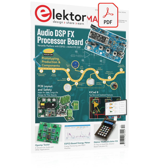
Elektor Digital Elektor November/December 2024 (PDF)
Elektor GREEN and GOLD members can download their digital edition here. Not a member yet? Click here. Audio DSP FX Processor BoardPart 1: Features and Design 50 Years of Elektor in English KiCad 8Top New and Updated Features Elektor MultiCalculator KitAn Arduino-Based Calculator Kit for Electronic Purposes Low-Cost GNSS RTK SystemsWith Centimeter-Level Degree of Accuracy PCB Layout and SafetyHints for a Safe, Long-Life Design of Your Boards Opamp TesterFor Audio and Other Applications Project Update #4: ESP32-Based Energy MeterEnergy Monitoring with MQTT Real-Time Spectrum Analyzer with Waveguide Technology and Multi-Interface PCsAaronia Establishes New Product Segment and Presents First Prototypes at Electronica in Munich Applications of Ynvisible’s E-paper DisplaysTransform Businesses and Shape the Future SMT InductorsCoils and Ferrites — Selection Made Easy Arrow Electronics to Showcase Innovative Technologies at electronica 2024 Using EMI Shielding to Achieve Electromagnetic Compatibility Compliance The Ultimate Tool for Every Electronics EnthusiastUnlock Endless Possibilities with Red Pitaya and 1,000+ Click Boards™ V-LD1 Distance Radar Module Siglent Presents Its New Vector Network Analyzer Platform SNA6000A HDI in the MiddleA New Cost-Effective PCB Pooling Service for Tiny BGAs Remote Access IoT LabOne and Only Solution for Remote Learning and Development in Embedded Industry Challenges of DFM Analysis for Flex and Rigid-Flex Design From Life's ExperienceMicrotechnophobia 3D Christmas TreeA 3D PCB with a Low-Cost, 32-bit Microcontroller Starting Out in Electronics……Continues with the Opamp! An Autonomous Sensor Node (Project Update #1)Reducing Idle Power Consumption with External RTC and Power Switch 2024: An AI OdysseyA Look Back at the Future LED Displays with the MAX7219A Hands-On Approach to a Great Chip Err-lectronicsCorrections, Updates, and Readers’ Letters VibroTactile GlovesA Breakthrough for Parkinson’s Patients
€ 7,50
-
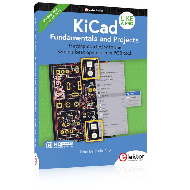
Elektor Publishing KiCad Like A Pro – Fundamentals and Projects
Getting started with the world’s best open-source PCB tool The latest iteration of KiCad, the world’s best free-to-use Printed Circuit Board tool, is packed with features usually found only in expensive commercial CAD tools. This modern, cross-platform application suite built around schematic and design editors, with auxiliary applications is a stable and mature PCB tool. KiCad 8 is a perfect fit for electronic engineers and makers. Here are the most significant improvements and features in KiCad 8, both over and under the hood: Modern user interface, completely redesigned from earlier versions Improved and customizable electrical and design rule checkers Theme editor allowing you to customize KiCad on your screen Ability to import projects from Eagle, CADSTART, and more Python scripting API Improved integrated SPICE circuit simulator Multi-sheet schematics Filters define selectable elements Enhanced interactive router helps you draw single tracks and differential pairs with precision New or enhanced tools to draw tracks, measure distances, tune track lengths, etc. Advanced interactive router Built-in bill of materials generator Realistic ray-tracing capable 3D viewer Customizable teardrops Plug-in manager for quick installation of themes, libraries and functionalities such as autorouters and BOM generators This book will teach you to use KiCad through a practical approach. It will help you become productive quickly and start designing your own boards. Example projects illustrate the basic features of KiCad, even if you have no prior knowledge of PCB design. The author describes the entire workflow from schematic entry to the intricacies of finalizing the files for PCB production and offers sound guidance on the process. Further full-fledged projects, of incremental difficulty, will be presented in a second book, together with a variety of advanced recipes.
€ 54,95
Members: € 49,46
-

Elektor Digital KiCad Like A Pro – Fundamentals and Projects (E-book)
Getting started with the world’s best open-source PCB tool The latest iteration of KiCad, the world’s best free-to-use Printed Circuit Board tool, is packed with features usually found only in expensive commercial CAD tools. This modern, cross-platform application suite built around schematic and design editors, with auxiliary applications is a stable and mature PCB tool. KiCad 8 is a perfect fit for electronic engineers and makers. Here are the most significant improvements and features in KiCad 8, both over and under the hood: Modern user interface, completely redesigned from earlier versions Improved and customizable electrical and design rule checkers Theme editor allowing you to customize KiCad on your screen Ability to import projects from Eagle, CADSTART, and more Python scripting API Improved integrated SPICE circuit simulator Multi-sheet schematics Filters define selectable elements Enhanced interactive router helps you draw single tracks and differential pairs with precision New or enhanced tools to draw tracks, measure distances, tune track lengths, etc. Advanced interactive router Built-in bill of materials generator Realistic ray-tracing capable 3D viewer Customizable teardrops Plug-in manager for quick installation of themes, libraries and functionalities such as autorouters and BOM generators This book will teach you to use KiCad through a practical approach. It will help you become productive quickly and start designing your own boards. Example projects illustrate the basic features of KiCad, even if you have no prior knowledge of PCB design. The author describes the entire workflow from schematic entry to the intricacies of finalizing the files for PCB production and offers sound guidance on the process. Further full-fledged projects, of incremental difficulty, will be presented in a second book, together with a variety of advanced recipes.
€ 44,95
Members: € 35,96


-
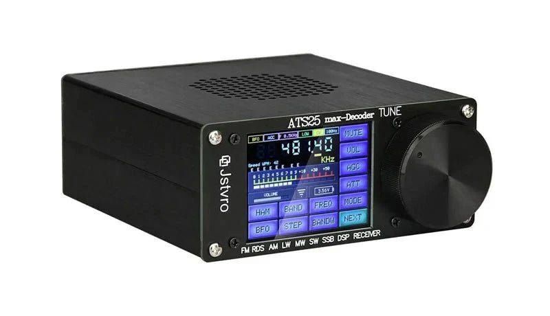
, by Jan Buiting Introducing the ATS25 Max: The Ultimate Ultra-Portable Decoder Receiver
Elektor proudly presents the ATS25 max-Decoder, a powerful yet ultra-compact multimode DSP receiver. This cutting-edge device offers comprehensive coverage of LW, SW, MW, FM, and...
-
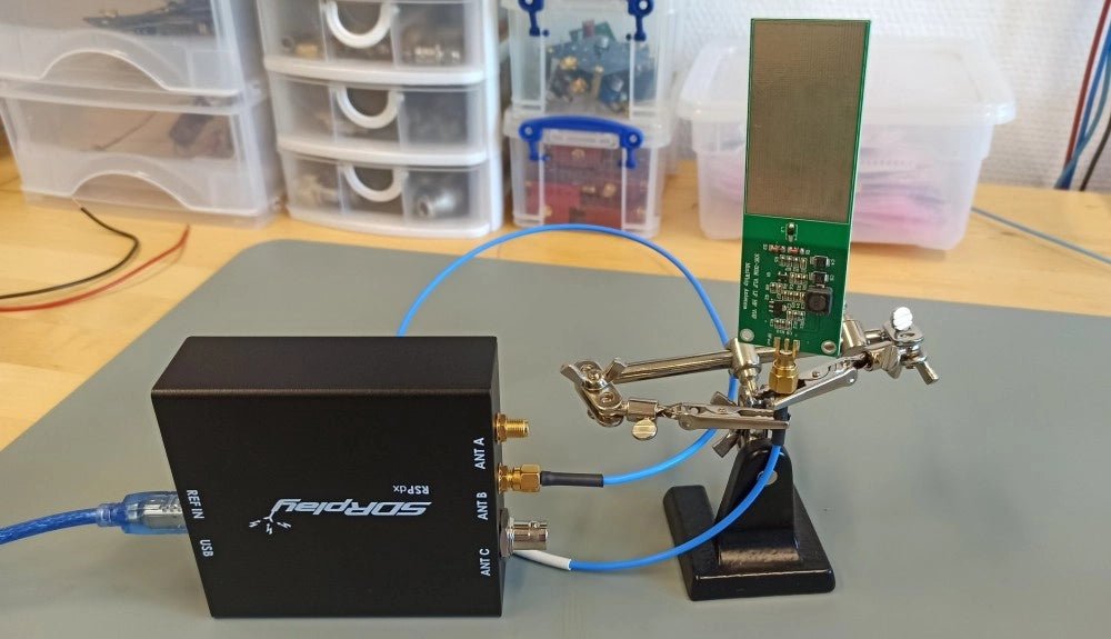
, by Sebastian Westerhold The SDRplay RSPdx SDR Receiver Features Frequency Range of 1 kHz up to 2 GHz (Review)
The SDRplay RSPdx is a 14-bit single-tuner receiver with continuous coverage from 1 kHz up to 2GHz. Three input connectors, an ample array of software...
-
, by Lobna Belarbi Kickstart Your Electronics Journey with Elektor’s Learning Collection
Whether you're new to electronics or aiming to level up your embedded skills, Elektor’s Learning Collection delivers expert-curated kits, courses, and hands-on bundles. The first...


