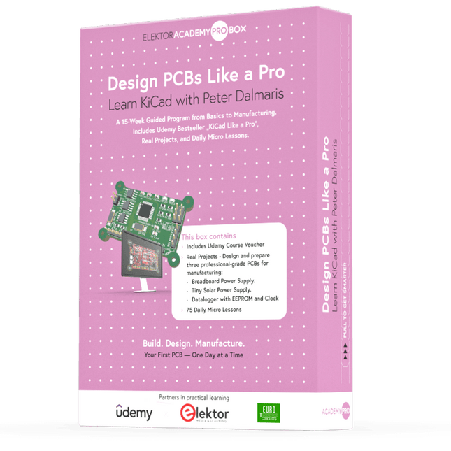
Learn KiCad with Peter Dalmaris
The Academy Pro Box "Design PCBs like a Pro" offers a complete, structured training programme in PCB design, combining online learning with practical application. Based on Peter Dalmaris’ KiCad course, the 15-week programme integrates video lessons, printed materials (2 books), and hands-on projects to ensure participants not only understand the theory but also develop the skills to apply it in practice.
Unlike standard courses, the Academy Pro Box provides a guided learning path with weekly milestones and physical components to design, test, and produce working PCBs. This approach supports a deeper learning experience and better knowledge retention.
The box is ideal for engineers, students, and professionals who want to develop practical PCB design expertise using open-source tools. With the added option to have their final project manufactured, participants complete the programme with real results – ready for use, testing, or further development.
Learn by doing
Build skills. Design real boards. Generate Gerbers. Place your first order. This isn’t just a course – it’s a complete project journey from idea to product.
You’ll walk away with:
Working knowledge of KiCad’s tools
Confidence designing your own PCBs
A fully manufacturable circuit board – made by you
What's inside the Box (Course)?
Both volumes of "KiCad Like a Pro" (valued at €105)
Vol 1: Fundamentals and Projects
Vol 2: Advanced Projects and Recipes
Coupon code to join the bestselling KiCad 9 online course by Peter Dalmaris on Udemy, featuring 20+ hours of video training. You'll complete three full design projects:
Breadboard Power Supply
Tiny Solar Power Supply
Datalogger with EEPROM and Clock
Voucher from Eurocircuits for the production of PCBs (worth €85 excl. VAT)
Learning Material (of this Box/Course)
15-Week Learning Program
▶ Click here to open
Week 1: Setup, Fundamentals, and First Steps in PCB Design
Week 2: Starting Your First PCB Project – Schematic Capture
Week 3: PCB Layout – From Netlist to Board Design
Week 4: Design Principles, Libraries, and Workflow
Week 5: Your First Real-World PCB Project
Week 6: Custom Libraries – Symbols, Footprints, and Workflow
Week 7: Advanced Tools – Net Classes, Rules, Zones, Routing
Week 8: Manufacturing Files, BOMs, and PCB Ordering
Week 9: Advanced Finishing Techniques – Graphics, Refinement, and Production Quality
Week 10: Tiny Solar Power Supply – From Schematic to Layout
Week 11: Tiny Solar Power Supply – PCB Layout and Production Prep
Week 12: ESP32 Clone Project – Schematic Design and Layout Prep
Week 13: ESP32 Clone – PCB Layout and Manufacturing Prep
Week 14: Final Improvements and Advanced Features
Week 15: Productivity Tools, Simulation, and Automation
KiCad Course with 18 Lessons on Udemy (by Peter Dalmaris)
▶ Click here to open
Introduction
Getting started with PCB design
Getting started with KiCad
Project: A hands-on tour of KiCad (Schematic Design)
Project: A hands-on tour of KiCad (Layout)
Design principles and PCB terms
Design workflow and considerations
Fundamental KiCad how-to: Symbols and Eeschema
Fundamental KiCad how-to: Footprints and Pcbnew
Project: Design a simple breadboard power supply PCB
Project: Tiny Solar Power Supply
Project: MCU datalogger with build-in 512K EEPROM and clock
Recipes
KiCad 9 new features and improvements
Legacy (from previous versions of KiCad)
KiCad 7 update (Legacy)
(Legacy) Gettings started with KiCad
Bonus lecture
About the Author
Dr. Peter Dalmaris, PhD is an educator, an electrical engineer and Maker. Creator of online video courses on DIY electronics and author of several technical books. As a Chief Tech Explorer since 2013 at Tech Explorations, the company he founded in Sydney, Australia, Peter's mission is to explore technology and help educate the world.
What is Elektor Academy Pro?
Elektor Academy Pro delivers specialized learning solutions designed for professionals, engineering teams, and technical experts in the electronics and embedded systems industry. It enables individuals and organizations to expand their practical knowledge, enhance their skills, and stay ahead of the curve through high-quality resources and hands-on training tools.
From real-world projects and expert-led courses to in-depth technical insights, Elektor empowers engineers to tackle today’s electronics and embedded systems challenges. Our educational offerings include Academy Books, Pro Boxes, Webinars, Conferences, and industry-focused B2B magazines – all created with professional development in mind.
Whether you're an engineer, R&D specialist, or technical decision-maker, Elektor Academy Pro bridges the gap between theory and practice, helping you master emerging technologies and drive innovation within your organization.
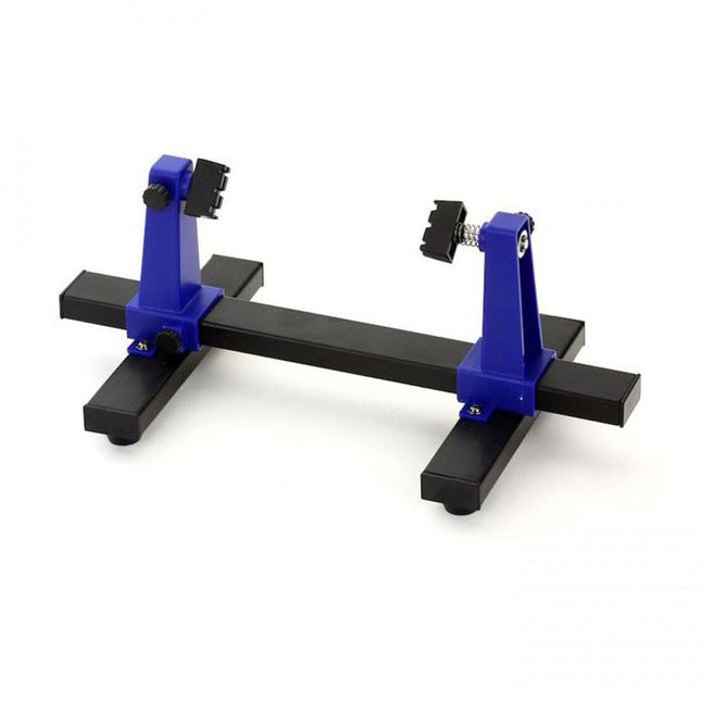
This adjustable circuit board holder is ideal for clamping PCB for soldering, desoldering or rework.
Features
2 adjustable grips on a retractable stand to accommodate various board sizes.
The adjustable clamps allow the PCB to rotate 360 degrees and stay set in any position.
The base of this rigid metal stand features four rubber feet to ensure stability.
Specifications
Product size
30 x 16.5 x 12.5 cm
Max. holding size
20 x 14 cm
Weight
450 g
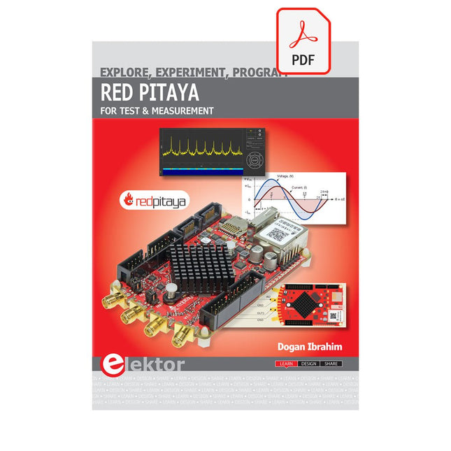
The Red Pitaya (STEMlab) is a credit card-sized, open-source test and measurement board that can be used to replace most measurement instruments used in electronics laboratories. With a single click, the board can transform into a web-based oscilloscope, spectrum analyser, signal generator, LCR meter, Bode plotter, and microcontroller.
The Red Pitaya (STEMlab) can replace the many pieces of expensive measurement equipment found at professional research organisations and teaching laboratories. The device, that based on Linux, includes an FPGA, digital signal processing (DSP), dual core ARM Cortex processor, signal acquisition and generation circuitry, micro USB socket, microSD card slot, RJ45 socket for Ethernet connection, and USB socket – all powered from an external mains adaptor.
This book is an introduction to electronics. It aims to teach the principles and applications of basic electronics by carrying out real experiments using the Red Pitaya (STEMlab). The book includes many chapters on basic electronics and teaches the theory and use of electronic components including resistors, capacitors, inductors, diodes, transistors, and operational amplifiers in electronic circuits. Many fun and interesting Red Pitaya (STEMlab) experiments are included in the book. The book also makes an introduction to visual programming environment.
The book is written for college level and first year university students studying electrical or electronic engineering.
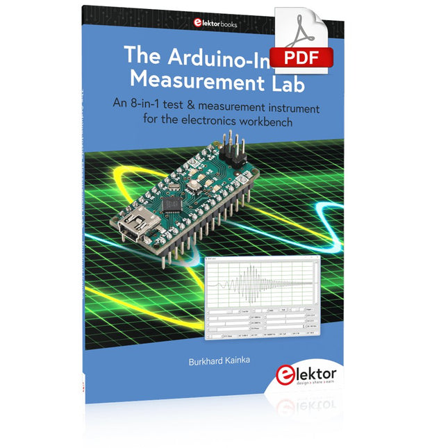
An 8-in-1 test & measurement instrument for the electronics workbench
A well-equipped electronics lab is crammed with power supplies, measuring devices, test equipment and signal generators. Wouldn‘t it be better to have one compact device for almost all tasks? Based on the Arduino, a PC interface is to be developed that’s as versatile as possible for measurement and control. It simply hangs on a USB cable and – depending on the software – forms the measuring head of a digital voltmeter or PC oscilloscope, a signal generator, an adjustable voltage source, a frequency counter, an ohmmeter, a capacitance meter, a characteristic curve recorder, and much more.
The circuits and methods collected here are not only relevant for exactly these tasks in the "MSR" electronics lab, but many details can also be used within completely different contexts.
This book is intended as a highly-practical guide for Hobbyists, Engineers and Scientists wishing to build measurement and control systems to be controlled by a local or remote Personal Computer running the Linux operating system. Both hardware and software aspects of designing typical embedded systems are covered in detail with schematics, code listings and full descriptions. Numerous examples have been designed to show clearly how straightforward it can be to create the interfaces between digital and analog electronics, with programming techniques for creating control software for both local and remote systems. Hardware developers will appreciate the variety of circuits, including a novel, low cost modulated wireless link and will discover how using Matlab® overcomes the need for specialist programming skills.
Software developers will appreciate how a better understanding of circuits plus the freedom offered by Linux to directly control at the register level enables them to optimize related programs. There is no need to buy special equipment or expensive software tools in order to create embedded projects covered in this book. You can build such quality systems quickly using popular low-cost electronic components and free distributed or low-cost software tools. Some knowledge of basic electronics plus the very basics of C programming only is required.
Many projects in this book are developed using Matlab® being a very popular worldwide computational tool for research in engineering and science. The book provides a detailed description of how to combine the power of Matlab® with practical electronics.
With an emphasis on learning by doing, readers are encouraged by examples to program with ease; the book provides clear guidelines as to the appropriate programming techniques “on the fly”. Complete and well-documented source code is provided for all projects.
If you want to learn how to quickly build Linux-based applications able to collect, process and display data on a PC from various analog and digital sensors, how to control circuitry attached to a computer, then even how to pass data via a network or control your embedded system wirelessly and more – then this is the book for you!
Features of this Book
Use the power, flexibility and control offered only by a Linux operating system on a PC.
Use a free, distributed downloadable GNU C compiler Use (optional) a low-cost Student Version of Matlab®.
Use low-cost electronic sub-assemblies for projects.
Improve your skills in electronics, programming, networking and wireless design.
A full chapter is dedicated to controlling your sound card for audio input and output purposes.
Program sound using OSS and ALSA.
Learn how to combine electronic circuits, software, networks and wireless technologies in the complete embedded system.
Clever Tricks with ATmega328 Pro Mini Boards
With a simple Pro Mini board and a few other components, projects that 20 or 30 years ago were unthinkable (or would have cost a small fortune) are realized easily and affordably in this book: From simple LED effects to a full battery charging and testing station that will put a rechargeable through its paces, there’s something for everyone.
All the projects are based on the ATmega328 microcontroller, which offers endless measuring, switching, and control options with its 20 input and output lines. For example, with a 7-segment display and a few resistors, you can build a voltmeter or an NTC-based thermometer. The Arduino platform offers the perfect development environment for programming this range of boards.
Besides these very practical projects, the book also provides the necessary knowledge for you to create projects based on your own ideas. How to measure, and what? Which transistor is suitable for switching a certain load? When is it better to use an IC? How do you switch mains voltage? Even LilyPad-based battery-operated projects are discussed in detail, as well as many different motors, from simple DC motors to stepper motors.
Sensors are another exciting topic: For example, a simple infrared receiver that can give disused remote controls a new lease on life controlling your home, and a tiny component that can actually measure the difference in air pressure between floor and table height!
Learn RC and RL Filters with Hands-On Circuits and Simulation
Introduction to Electronic Filters is your comprehensive guide to understanding, designing, and applying first-order electronic filters using resistors, capacitors, and inductors. Whether you are a student, maker, or educator, this book demystifies the theory behind RC and RL filters and bridges the gap between concepts and real-world applications through simulation and experimentation.
From the basics of frequency response and phase shift to hands-on breadboard builds and Python-based simulations, this book offers a deeply practical learning experience. You will learn to analyse filters using Bode plots and phasors, and explore applications in audio tone shaping, sensor signal conditioning, noise reduction, and power supply filtering.
As you progress, you’ll build, measure, simulate, and tune filters using modern tools like CircuitLab, Python, and the Analog Discovery 3. Each chapter includes thoughtfully crafted activities that reinforce learning by doing – designing filters for specific tasks, simulating dynamic behaviour, and observing how theory translates into performance.
Inside you’ll find:
A clear introduction to the fundamentals of electronic filters
Detailed explanations of RC and RL filters, cutoff frequency, and phase
Guided activities using both simulation and hardware tools
Real-life applications in audio, sensors, power supplies, and more
A beginner-friendly primer on Python and algebra for electronics
Whether you’re working through simulations or experimenting with real components on your workbench, this book will help you develop a solid understanding of electronic filters and their role in practical circuits.
PCBite is the complete solution handling your circuit board during the development phase. Powerful magnets together with a stainless base plate makes the system flexible, mobile and user friendly.
The holder can easily be repositioned to handle circuit boards of varying shape and sizes.
The probes are steady but yet flexible made for instant measurements or total hands-free operations together with your multimeter or prefered tool.
Included
4x PCBite holder
2x Banana to DuPont test wires red/black
2x SP10 probe with red/black probe head and pin tipped test needles
2x Extra crown tipped test needle
1x Set of yellow insulation washers
1x Large Baseplate (A4)
1x Microfiber cloth
Downloads
User Guide
The SQ series of handsfree PCBite probes from Sensepeek are insulated, come with included color-coded cable holders and have a lower point of gravity making them even more stable compared with the original SP series of probes. All the loved features of handsfree measurement, exchangeable fine pitch spring tipped test needle and the minimalistic design is maintained to make traditional sized and handheld probes obsolete.
Features
All handsfree probes from Sensepeek makes instant measurements or long triggering sessions a breeze.
No more soldering wires to connect your probe or complicated tools to setup, just positioning the probe needle on any test point or component in the signal path and release.
Saves time and frustration during development, verification and repairs.
The minimalist design and the spring-loaded test needle makes it possible to simultaneously measure on fine pitch components and nearby signals.
Both length and weight of the SQ probes are perfectly balanced to be used with PCBite PCB holders and base plate which is a must for handsfree function.
The probe holder comes with a powerful magnet in the base, as for all PCBite probes and holders which makes the probe easy to place and reposition.
The SQ series of probes can be used handheld without the probe holder as they have an insulated grip but their full potential is used when measuring handsfree.
Included
4x PCBite PCB holders
2x SQ10 probes and pin tipped test needles (red/black)
2x Banana to dupont test wires (red/black)
1x Large Base plate (A4)
1x Insulation cover for the base plate (A4)
1x Set of yellow insulation washers for the PCB holders
1x Set of cable holders (red/black)
2x Extra test needles
1x Micro fiber cloth
Downloads
User Guide (PCBite Kit)
User Guide (SQ10)
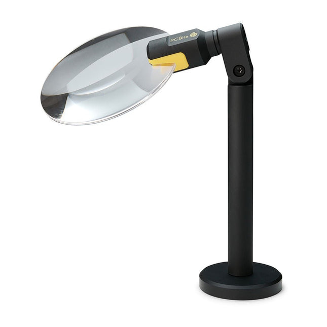
The PCBite Magnifier (premium build quality made from CNC machined aluminum) enlarges your target and makes it easier to see during soldering, inspection and measurements. Especially useful when placing PCBite hands free probes on fine pitch SMD components during measurements.
3x magnification edgeless lens for increased visibility of the work surface and AR coating (anti-reflection) to reduce reflections from nearby light sources.
Optimized design, magnification and focal point for use together with the PCBite PCB holders and baseplates included in all PCBite kits. Can also be used handheld but not standalone without a metal surface as base.
At the bottom of the magnifier foot there is a strong magnet perfectly balanced in strength. A low friction bottom cap protects the magnet and the baseplate to make the magnifier easy to slide when repositioning or removing the magnifier from the baseplate.
Friction based adjustment of lens tilt and rotate positions takes away the need for annoying and complicated set screws.
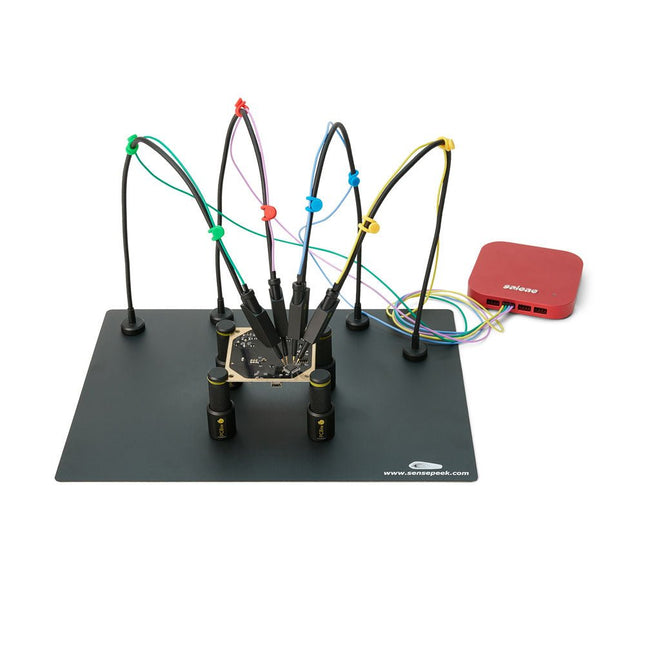
The SQ series of handsfree PCBite probes from Sensepeek are insulated, come with included color-coded cable holders and have a lower point of gravity making them even more stable compared with the original SP series of probes. All the loved features of handsfree measurement, exchangeable fine pitch spring tipped test needle and the minimalistic design is maintained to make traditional sized and handheld probes obsolete.
Features
All handsfree probes from Sensepeek makes instant measurements or long triggering sessions a breeze.
No more soldering wires to connect your probe or complicated tools to setup, just positioning the probe needle on any test point or component in the signal path and release.
Saves time and frustration during development, verification and repairs.
The minimalist design and the spring-loaded test needle makes it possible to simultaneously measure on fine pitch components and nearby signals.
Both length and weight of the SQ probes are perfectly balanced to be used with the included PCB holders and base plate which is a must for handsfree function.
The probe holder comes with a powerful magnet in the base, as for all PCBite probes and holders which makes the probe easy to place and reposition.
The SQ series of probes can be used handheld without the probe holder as they have an insulated grip but their full potential is used when measuring handsfree.
One side of the included baseplate is matte and the other is mirror polished. The mirror polished surface makes it easy to see components on the circuit board underside. For added protection during measurement the included insulation cover can be mounted on one of the surfaces.
Included
4x PCBite PCB holders
1x Set of yellow insulation washers for the PCB holders
1x Large Base plate (A4)
1x Insulation cover for the base plate (A4)
1x Micro fiber cloth
4x SQ10 probes and pin tipped test needles (black)
2x Banana to dupont test wires (red/black)
5x Dupont to dupont test wires
1x Set of cable holders (4 colors)
4x Extra test needles
Downloads
User guide (PCBite kit)
User guide (SQ10 probes)
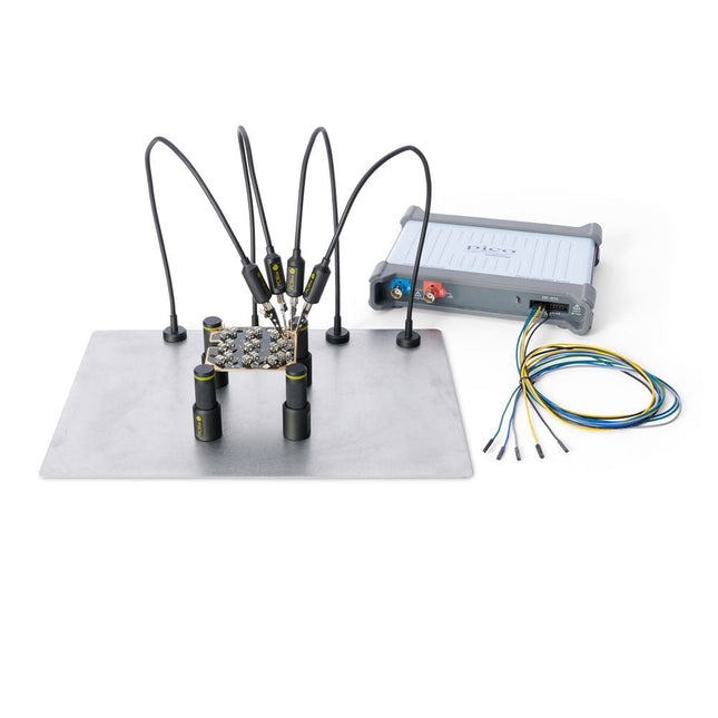
The minimalist design and the spring loaded test needle makes it possible to simultaneously measure on fine pitch components and nearby signals.
The probe is steady but yet flexible made for instant measurements or total hands-free operations together with your multimeter, logic analyzer or preferred tool.
The dual pin header connector fits directly on a 2.54 mm (0.100”) connector.
The SP10 comes with a powerful magnet in the base, as for all PCBite probes and holders which makes the probe easy to place and reposition.
Included
4x PCBite holder
1x Large base plate (A4)
4x PCBite probe with pin tipped test needle
4x Extra crown tipped test needle
1x Set of yellow insulation washers
5x Dupont to dupont test wire
2x Banana to dupont test wire
1x Microfiber cloth
Downloads
User Guide