Search results for "mastering OR microcontrollers OR helped OR by OR arduino OR chapter OR 11 OR pdf"
-
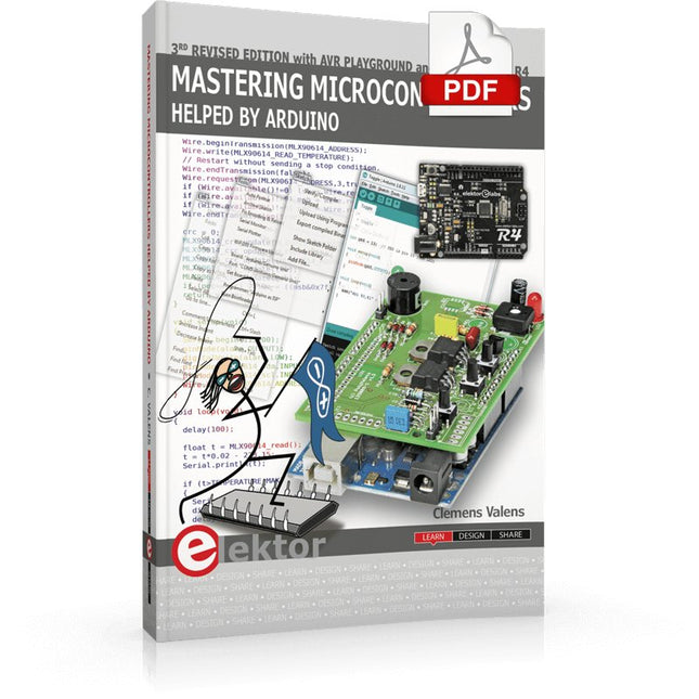
Elektor Digital Mastering Microcontrollers Helped by Arduino (3rd Edition) | E-book
Third, extended and revised edition with AVR Playground and Elektor Uno R4 Arduino boards have become hugely successful. They are simple to use and inexpensive. This book will not only familiarize you with the world of Arduino but it will also teach you how to program microcontrollers in general. In this book theory is put into practice on an Arduino board using the Arduino programming environment. Some hardware is developed too: a multi-purpose shield to build some of the experiments from the first 10 chapters on; the AVR Playground, a real Arduino-based microcontroller development board for comfortable application development, and the Elektor Uno R4, an Arduino Uno R3 on steroids. The author, an Elektor Expert, provides the reader with the basic theoretical knowledge necessary to program any microcontroller: inputs and outputs (analog and digital), interrupts, communication busses (RS-232, SPI, I²C, 1-wire, SMBus, etc.), timers, and much more. The programs and sketches presented in the book show how to use various common electronic components: matrix keyboards, displays (LED, alphanumeric and graphic color LCD), motors, sensors (temperature, pressure, humidity, sound, light, and infrared), rotary encoders, piezo buzzers, pushbuttons, relays, etc. This book will be your first book about microcontrollers with a happy ending! This book is for you if you are a beginner in microcontrollers, an Arduino user (hobbyist, tinkerer, artist, etc.) wishing to deepen your knowledge,an Electronics Graduate under Undergraduate student or a teacher looking for ideas. Thanks to Arduino the implementation of the presented concepts is simple and fun. Some of the proposed projects are very original: Money Game Misophone (a musical fork) Car GPS Scrambler Weather Station DCF77 Decoder Illegal Time Transmitter Infrared Remote Manipulator Annoying Sound Generator Italian Horn Alarm Overheating Detector PID Controller Data Logger SVG File Oscilloscope 6-Channel Voltmeter All projects and code examples in this book have been tried and tested on an Arduino Uno board. They should also work with the Arduino Mega and every other compatible board that exposes the Arduino shield extension connectors. Please note For this book, the author has designed a versatile printed circuit board that can be stacked on an Arduino board. The assembly can be used not only to try out many of the projects presented in this book but also allows for new exercises that in turn provide the opportunity to discover new techniques. Also available is a kit of parts including the PCB and all components. With this kit you can build most of the circuits described in the book and more. Datasheets Active Components Used (.PDF file): ATmega328 (Arduino Uno) ATmega2560 (Arduino Mega 2560) BC547 (bipolar transistor, chapters 7, 8, 9) BD139 (bipolar power transistor, chapter 10) BS170 (N-MOS transistor, chapter 8) DCF77 (receiver module, chapter 9) DS18B20 (temperature sensor, chapter 10) DS18S20 (temperature sensor, chapter 10) HP03S (pressure sensor, chapter 8) IRF630 (N-MOS power transistor, chapter 7) IRF9630 (P-MOS power transistor, chapter 7) LMC6464 (quad op-amp, chapter 7) MLX90614 (infrared sensor, chapter 10) SHT11 (humidity sensor, chapter 8) TS922 (dual op-amp, chapter 9) TSOP34836 (infrared receiver, chapter 9) TSOP1736 (infrared receiver, chapter 9) MPX4115 (analogue pressure sensor, chapter 11) MCCOG21605B6W-SPTLYI (I²C LCD, chapter 12) SST25VF016B (SPI EEPROM, chapter 13) About the author Clemens Valens, born in the Netherlands, lives in France since 1997. Manager at Elektor Labs and Webmaster of ElektorLabs, in love with electronics, he develops microcontroller systems for fun, and sometimes for his employer too. Polyglot—he is fluent in C, C++, PASCAL, BASIC and several assembler dialects—Clemens spends most of his time on his computer while his wife, their two children and two cats try to attract his attention (only the cats succeed). Visit the author’s website: www.polyvalens.com.Authentic testimony of Hervé M., one of the first readers of the book:'I almost cried with joy when this book made me understand things in only three sentences that seemed previously completely impenetrable.'
€ 34,95
Members: € 27,96
-

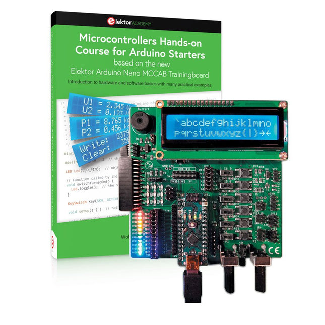
Elektor Publishing Hands-on Microcontroller Course for Advanced Arduino Users
32 new Projects, Practical Examples and Exercises with the Elektor Arduino Nano MCCAB Training Board Electronics and microcontroller technology offer the opportunity to be creative. This practical microcontroller course provides you with the chance to bring your own Arduino projects and experience such moments of success. Ideally, everything works as you imagined when you switch it on for the first time. In practice, however, things rarely work as expected. At that point, you need knowledge to efficiently search for and find the reason for the malfunction. In this book for advanced users, we delve deep into the world of microcontrollers and the Arduino IDE to learn new procedures and details, enabling you to successfully tackle and solve even more challenging situations. With this book, the author gives the reader the necessary tools to create projects independently and also to be able to find errors quickly. Instead of just offering ready-made solutions, he explains the background, the hardware used, and any tools required. He sets tasks in which the reader contributes their own creativity and writes the Arduino sketch themselves. If you don’t have a good idea and get stuck, there is, of course, a suggested solution for every project and every task, along with the corresponding software, which is commented on and explained in detail in the book. This practical course will teach you more about the inner workings of the Arduino Nano and its microcontroller. You will get to know hardware modules that you can use to realize new and interesting projects. You will familiarize yourself with software methods such as ‘state machines,’ which can often be used to solve problems more easily and clearly. The numerous practical projects and exercise sketches are once again realized on the Arduino Nano MCCAB Training Board, which you may already be familiar with from the course book ‘Microcontrollers Hands-on Course for Arduino Starters’, and which contains all the hardware peripherals and operating elements we need for the input/output operations of our sketches. Readers who do not yet own the Arduino Nano MCCAB Training Board can purchase the required hardware separately, or alternatively, build it on a breadboard.
€ 49,95
Members: € 44,96
-

Elektor Publishing Mastering the Arduino Uno R4
Programming and Projects for the Minima and WiFi Based on the low-cost 8-bit ATmega328P processor, the Arduino Uno R3 board is likely to score as the most popular Arduino family member, and this workhorse has been with us for many years. Eleven years later, the long-overdue successor, the Arduino Uno R4, was released. It is built around a 48 MHz, 32-bit Arm Cortex-M4 microcontroller and provides significantly expanded SRAM and Flash memory. Additionally, a higher-precision ADC and a new DAC are added to the design. The Uno R4 board also supports the CAN Bus with an interface. Two versions of the board are available: Uno R4 Minima, and Uno R4 WiFi. This book is about using these new boards to develop many different and interesting projects with just a handful of parts and external modules. All projects described in the book have been fully tested on the Uno R4 Minima or the Uno R4 WiFi board, as appropriate. The project topics include the reading, control, and driving of many components and modules in the kit as well as on the relevant Uno R4 board, including LEDs 7-segment displays (using timer interrupts) LCDs Sensors RFID Reader 4x4 Keypad Real-time clock (RTC) Joystick 8×8 LED matrix Motors DAC (Digital-to-analog converter) LED matrix WiFi connectivity Serial UART CAN bus Infrared controller and receiver Simulators … all in creative and educational ways with the project operation and associated software explained in great detail.
€ 39,95
Members: € 35,96
-
Elektor Bundles Microcontrollers Hands-on Course for Arduino Starters (Bundle)
Realize your own projects with the Elektor Arduino Nano MCCAB Training Board The microcontroller is probably the most fascinating subfield of electronics. Due to the multitude of functions, it combines on its chip, it is a universal multi-tool for developers to realize their projects. Practically every device of daily use today is controlled by a microcontroller. However, for an electronic layman, realizing his own ideas with a microcontroller has so far remained a pipe dream due to its complexity. The Arduino concept has largely simplified the use of microcontrollers, so that now even laymen can realize their own electronics ideas with a microcontroller. Book & Hardware in the Bundle: 'Learning by Doing' This book, which is included in the bundle, shows how you can realize your own projects with a microcontroller even without much experience in electronics and programming languages. It is a microcontrollers hands-on course for starters, because after an overview of the internals of the microcontroller and an introduction to the programming language C, the focus of the course is on the practical exercises. The reader acquires the necessary knowledge by 'learning by doing': in the extensive practical section with 12 projects and 46 exercises, what is learned in the front part of the book is underpinned with many examples. The exercises are structured in such a way that the user is given a task to solve using the knowledge built up in the theoretical part of the book. Each exercise is followed by a sample solution that is explained and commented on in detail, which helps the user to solve problems and compare it with his own solution. Arduino IDE The Arduino IDE is a software development environment that can be downloaded for free to your own PC and that contains the entire software package needed for your own microcontroller projects. You write your programs ('apps') with the IDE’s editor in the C programming language. You translate them into the bits and bytes that the microcontroller understands using the Arduino IDE's built-in compiler, and then load them into the microcontroller's memory on the Elektor Arduino MCCAB Nano Training Board via a USB cable. Query or control external sensors, motors or assemblies In addition to an Arduino Nano microcontroller module, the Elektor Arduino Nano MCCAB Training Board contains all the components required for the exercises, such as light-emitting diodes, switches, pushbuttons, acoustic signal transmitters, etc. External sensors, motors or assemblies can also be queried or controlled with this microcontroller training system. Specifications (Arduino Nano MCCAB Training Board) Power Supply Via the USB connection of the connected PC or an external power supply unit (not included) Operating Voltage +5 Vcc Input Voltage All inputs 0 V to +5 V VX1 and VX2 +8 V to +12 V (only when using an external power supply) Hardware periphery LCD 2x16 characters Potentiometer P1 & P2 JP3: selection of operating voltage of P1 & P2 Distributor SV4: Distributor for the operating voltagesSV5, SV6: Distributor for the inputs/outputs of the microcontroller Switches and buttons RESET button on the Arduino Nano module 6x pushbutton switches K1 ... K6 6x slide switches S1 ... S6 JP2: Connection of the switches with the inputs of the microcontroller Buzzer Piezo buzzer Buzzer1 with jumper on JP6 Indicator lights 11 x LED: Status indicator for the inputs/outputs LED L on the Arduino Nano module, connected to GPIO D13 JP6: Connection of LEDs LD10 ... LD20 with GPIOs D2 ... D12 Serial interfacesSPI & I²C JP4: Selection of the signal at pin X of the SPI connector SV12 SV9 to SV12: SPI interface (3.3 V/5 V) or I²C interface Switching output for external devices SV1, SV7: Switching output (maximum +24 V/160 mA, externally supplied) SV2: 2x13 pins for connection of external modules 3x3 LED matrix(9 red LEDs) SV3: Columns of the 3x3 LED matrix (outputs D6 ... D8) JP1: Connection of the rows with the GPIOs D3 ... D5 Software Library MCCABLib Control of hardware components (switches, buttons, LEDs, 3x3 LED matrix, buzzer) on the MCCAB Training Board Operating Temperature Up to +40 °C Dimensions 100 x 100 x 20 mm Specifications (Arduino Nano) Microcontroller ATmega328P Architecture AVR Operating Voltage 5 V Flash Memory 32 KB, of which 2 KB used by bootloader SRAM 2 KB Clock Speed 16 MHz Analog IN Pins 8 EEPROM 1 KB DC Current per I/O Pins 40 mA on one I/O pin, total maximum 200 mA on all pins together Input Voltage 7-12 V Digital I/O Pins 22 (6 of which are PWM) PWM Output 6 Power Consumption 19 mA Dimensions 18 x 45 mm Weight 7 g Included Elektor Arduino Nano MCCAB Training Board Arduino Nano Book: Microcontrollers Hands-on Course for Arduino Starters
€ 139,95€ 119,95
Best Price
-
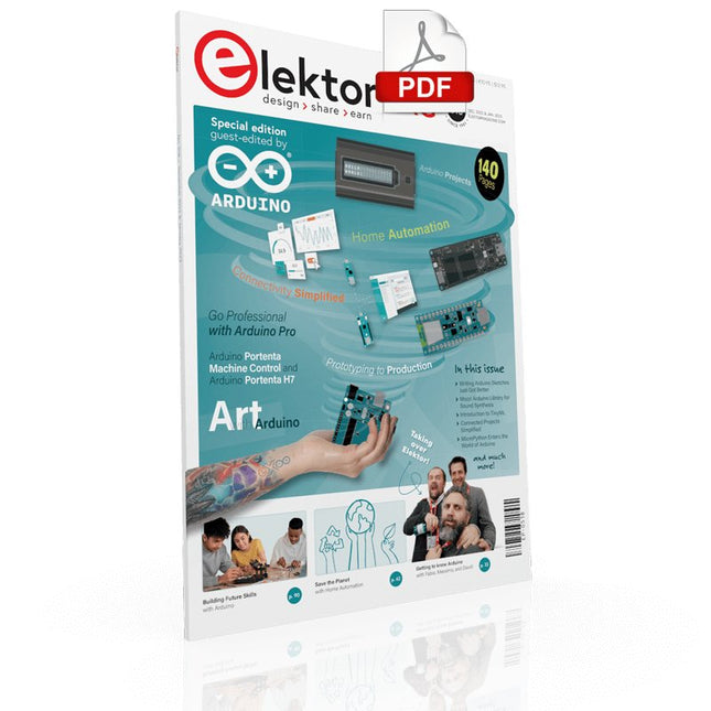
Elektor Digital Elektor Arduino Guest Edition 2022 (PDF) EN
Elektor GREEN and GOLD members can download their digital edition here. Not a member yet? Click here. Arduino Portenta Machine Control and Arduino Portenta H7A CAN-to-MQTT Gateway Demo Project Unboxing the Elektor LCR Meter with David Cuartielles MicroPython Enters the World of Arduino Connected Projects, SimplifiedDive Into the Arduino Cloud Introduction to TinyMLBig Is Not Always Better Arduino K-Way Writing Arduino Sketches Just Got Better Get to Know Arduino Getting Started with the Portenta X8Manage Software Securely with Containers Build, Deploy, and Maintain Scalable, Secure ApplicationsWith Arduino Portenta X8 Featuring NXP’s i.MX 8M Mini Applications Processor and EdgeLock SE050 Secure Element How I Automated My HomeArduino CEO Fabio Violante Shares Solutions Altair 8800 SimulatorHardware Simulation of a Vintage Computer MS-DOS on the Portenta H7Run Old-School Software on Contemporary Hardware Grow It YourselfA Digitally Controlled, Single-Box Solution for Indoor Farming Save the Planet With Home Automation?MQTT on the Arduino Nano RP2040 Connect Go Professional with Arduino Pro Smart Ovens Take a Leap Into the Future Tagvance Builds Safer Construction Sites with Arduino Santagostino Breathes Easywith Remote Monitoring that Leverages AI for Predictive Maintenance Security Flies High with RIoT Secure’s MKR-Based Solution Open-Source Brings a New Generation of Water Management to the World SensoDetect Deforestation with Sound Analysis The Mozzi Arduino Library for Sound SynthesisInsights from Tim Barrass The New Portenta X8 (with Linux!) and Max Carrier Redefine What’s Possible How Using Arduino Helps Students Build Future Skills Must-Haves for Your Electronics Workspace The Importance of Robotics in Education Dependable IoT Based Upon LoRa Unboxing the Portenta Machine Control 8-Bit Gaming with Arduboy Reducing Water Usage at Horseback Riding TracksAn IoT to Constantly Monitor Soil Humidity and Temperature Levels The Panettone ProjectA sourdough starter management and maintenance system Supporting Arduino Resellers Space Invaders with Arduino Art with ArduinoInspiring Insights from Artists and Designers Arduino Product Catalogue The Future of Arduino
€ 7,50
-

Elektor Digital Mastering the Arduino Uno R4 (E-book)
Programming and Projects for the Minima and WiFi Based on the low-cost 8-bit ATmega328P processor, the Arduino Uno R3 board is likely to score as the most popular Arduino family member, and this workhorse has been with us for many years. Eleven years later, the long-overdue successor, the Arduino Uno R4, was released. It is built around a 48 MHz, 32-bit Arm Cortex-M4 microcontroller and provides significantly expanded SRAM and Flash memory. Additionally, a higher-precision ADC and a new DAC are added to the design. The Uno R4 board also supports the CAN Bus with an interface. Two versions of the board are available: Uno R4 Minima, and Uno R4 WiFi. This book is about using these new boards to develop many different and interesting projects with just a handful of parts and external modules. All projects described in the book have been fully tested on the Uno R4 Minima or the Uno R4 WiFi board, as appropriate. The project topics include the reading, control, and driving of many components and modules in the kit as well as on the relevant Uno R4 board, including LEDs 7-segment displays (using timer interrupts) LCDs Sensors RFID Reader 4x4 Keypad Real-time clock (RTC) Joystick 8×8 LED matrix Motors DAC (Digital-to-analog converter) LED matrix WiFi connectivity Serial UART CAN bus Infrared controller and receiver Simulators … all in creative and educational ways with the project operation and associated software explained in great detail.
€ 32,95
Members: € 26,36
-
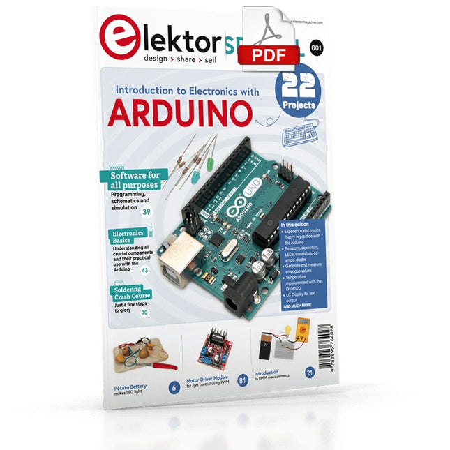
Elektor Digital Elektor Special: Introduction to Electronics with Arduino (PDF)
Although the Arduino isn’t a novelty any longer, there are still many beginners who want to try programming and development with a microcontroller, and to them, it is all new. All beginnings can be difficult, though they should be light and enjoyable. You do not need much or expensive equipment for the examples. The circuits are built on a small breadboard, and, if necessary, connected to an Arduino Uno, which you can program on a Windows PC. You will find clear examples of how to build all circuits, ensuring easy and error-free reproduction. Projects Discussed Current & Voltage – How it all began Arduino Hardware Arduino Programming The Electrical Circuit Measuring with the Multimeter Circuit Diagrams and Breadboards Creating Circuit Diagrams Breadboard Views with Fritzing Online Circuit Simulation Indispensable: Resistors (Part 1) Hands-on with Resistors (Part 2) Variable Resistors Diodes: One-way Street for Current The Transistor Switch Electromagnetism Relays and Motors op-amps: Operational Amplifiers Capacitors The NE555 Timer PWM and Analogue Values with Arduino 7-Segment Temperature Display Introduction to Soldering and LCDs
€ 11,95
Members: € 10,76
-
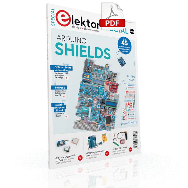
Elektor Digital Elektor Special: Arduino Shields (PDF) EN
Make your project dreams come true: an odometer for the hamster wheel, a fully automatic control of your ant farm with web interface, or the Sandwich-O-Mat – a machine that toasts and grills sandwiches of your choice. With the Arduino and the DIY or Maker movement, not only did entry into microcontroller programming become child's play, but a second development also took place: Resourceful developers brought small boards – so-called shields or modules – to the market, which greatly simplified the use of additional hardware. The small modules contain all the important electronic parts to be connected to the microcontroller with a few plug-in cables, eliminating the need for a fiddly and time-consuming assembly on the plug-in board. In addition, it is also possible to handle tiny components that do not have any connecting legs (so-called SMDs). Projects Discussed Arduino seeks connection BMP and introduction to libraries, I²C Learn I/O basics with the multi-purpose shield I²C LCD adapter and DOT matrix displays LCD keypad shield Level converter W5100: Internet connection I/O expansion shield Relays and solid-state relays The multi-function shield: A universal control unit Connecting an SD card reader via SPI Keys and 7-segment displays 16-bit ADC MCP4725 DAC 16-way PWM servo driver MP3 player GPS data logger using an SD card Touch sensor Joystick SHT31: Temperature and humidity VEML6070 UV-A sensor VL53L0X time-of-flight Ultrasonic distance meter MAX7219-based LED DOT matrix display DS3231 RTC Port expander MCP23017 433 MHz radio MPU-650 gyroscope ADXL345 accelerometer WS2812 RGB LEDs Power supply MQ-xx gas sensors CO2 gas sensor ACS712 current sensor INA219 current sensor L298 motor driver MFRC522 RFID 28BYJ-48 stepper motor TMC2209 silent step stick X9C10x digital potentiometer ST7735 in a color TFT display e-Paper display Bluetooth Geiger counter SIM800L GSM module I²C multiplexer Controller Area Network
€ 11,95
Members: € 10,76
-

Elektor Labs Elektor Arduino MultiCalculator
The Elektor MultiCalculator Kit is an Arduino-based multifunction calculator that goes beyond basic calculations. It offers 22 functions including light and temperature measurement, differential temperature analysis, and NEC IR remote control decoding. The Elektor MultiCalculator is a handy tool for use in your projects or for educational purposes. The kit features a Pro Mini module as the computing unit. The PCB is easy to assemble using through-hole components. The enclosure consists of 11 acrylic panels and mounting materials for easy assembly. Additionally, the device is equipped with a 16x2 alphanumeric LCD, 20 buttons, and temperature sensors. The Elektor MultiCalculator is programmable with the Arduino IDE through a 6-way PCB header. The available software is bilingual (English and Dutch). The calculator can be programmed with a programming adapter, and it is powered through USB-C. Modes of Operation Calculator 4-Ring Resistor Code 5-Ring Resistor Code Decimal to Hexadecimal and Character (ASCII) conversion Hexadecimal to Decimal and Character (ASCII) conversion Decimal to Binary and Character (ASCII) conversion Binary to Decimal and Hexadecimal conversion Hz, nF, capacitive reactance (XC) calculation Hz, µH, inductive reactance (XL) calculation Resistance calculation of two resistors connected in parallel Resistance calculation of two resistors connected in series Calculation of unknown parallel resistor Temperature measurement Differential temperature measurement T1&T2 and Delta (δ) Light measurement Stopwatch with lap time function Item counter NEC IR remote control decoding AWG conversion (American Wire Gauge) Rolling Dice Personalize startup message Temperature calibration Specifications Menu languages: English, Dutch Dimensions: 92 x 138 x 40 mm Build time: approx. 5 hours Included PCB and though-hole components Precut acrylic sheets with all mechanical parts Pro Mini microcontroller module (ATmega328/5 V/16 MHz) Programming adapter Waterproof temperature sensors USB-C cable Downloads Software
€ 49,95€ 39,95
Best Price
-

Elektor Academy Pro Arduino (Programming Course)
This complete Arduino Uno-based microcontroller programming course features a textbook, a component kit, hands-on projects, and a comprehensive online course with simulations. It is ideal for step-by-step learning of embedded systems programming with Arduino using a practical, hands-on approach. A Practical Introduction to Embedded Systems with the Arduino Uno This course is designed for people who are new to embedded systems and looking for a structured, example-driven way to get started. A kit of parts comprising LEDs and resistors, switches, sensors and actuators, displays, a breadboard and wires, and more is included. These are used in the course to illustrate example applications. No prior experience with Arduino or embedded development is required. Each section features hands-on examples and mini projects designed to reinforce key concepts and inspire deeper exploration. By the end of the course, you’ll be able not only to reproduce the examples but also to build on them with your own ideas and applications. What Will You Learn? Microcontroller programming with Arduino using the Uno R3 board Working with Digital I/O, read buttons and encoders, control LEDs and relays Read analog inputs, voltages, and analog sensors Generating analog output signals and PWM Use serial communication like UART, I²C and SPI to control displays and read digital sensors and SD cards Managing time Working with interrupts Real-time sensor input and control via buttons, LEDs, and displays Control actuators like relays and servo motors Who Is It For? Students and self-learners exploring embedded systems Makers and IoT enthusiasts looking to improve their hardware skills Educators and trainers seeking ready-to-teach material What's Inside the Box? Access to the full course on the Elektor Academy Pro Learning Platform Uno R3 microcontroller board + USB cable Book: Programming Microcontrollers in C/C++ Using Arduino Downloadable project files for every module Component Box: 2× LED, red, 5 mm LED, green, 5 mm 3× Resistor, 470 Ω, 0.25 W LDR Potentiometer, 10 kΩ, linear Pushbutton Rotary encoder module Relay module DHT22 Humidity & Temperature Sensor TM1637-compatible 4-digit 7-segment display MPU-6050 IMU with headers SSD1306-compatible I²C OLED display Micro SD card adapter with header Buzzer SG90 Micro Servo ILI9341-compatible SPI 240×320 TFT display 20× Jumper wires Breadboard All Programming Courses (and differences in content) Course Arduino Raspberry Pi Pico with Arduino C/C++ ESP32 with Arduino C/C++ Raspberry Pi Pico with MicroPython ESP32 with MicroPython Online Course Access to Arduino Course Access to Pico with Arduino C/C++ Course Access to ESP32 with Arduino C/C++ Course Access to Pico with MicroPython Course Access to ESP32 with MicroPython Course Board Uno R3 Raspberry Pi Pico ESP32 Raspberry Pi Pico ESP32 Book Programming Microcontrollers in C/C++ Using Arduino Programming Microcontrollers in C/C++ Using Arduino Programming Microcontrollers in C/C++ Using Arduino Programming Microcontrollers in MicroPython Programming Microcontrollers in MicroPython Kit 40-piece Component Box 40-piece Component Box 40-piece Component Box 40-piece Component Box 40-piece Component Box
€ 69,95
Members: € 62,96
-
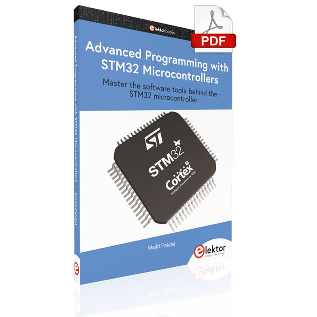
Elektor Digital Advanced Programming with STM32 Microcontrollers (E-book)
Master the software tools behind the STM32 microcontroller This book is project-based and aims to teach the software tools behind STM32 microcontroller programming. Author Majid Pakdel has developed projects using various different software development environments including Keil MDK, IAR Embedded Workbench, Arduino IDE and MATLAB. Readers should be able to use the projects as they are, or modify them to suit to their own needs. This book is written for students, established engineers, and hobbyists. STM32 microcontroller development boards including the STM32F103 and STM32F407 are used throughout the book. Readers should also find it easy to use other ARM-based development boards. Advanced Programming with STM32 Microcontrollers includes: Introduction to easy-to-use software tools for STM32 Accessing the features of the STM32 Practical, goal oriented learning Complete code available online Producing practical projects with ease Topics cover: Pulse Width Modulation Serial Communication Watchdog Timers I²C Direct Memory Access (DMA) Finite State Machine Programming ADCs and DACs External Interupts Timers and Counters
€ 29,95
Members: € 23,96
-
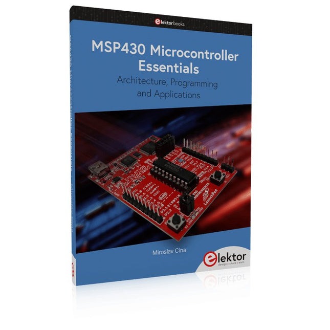
Elektor Publishing MSP430 Microcontroller Essentials
Architecture, Programming and Applications The MSP430 is a popular family of microcontrollers from Texas Instruments. In this book we will work with the smallest type, which is the powerful MSP430G2553. We will look at the capabilities of this microcontroller in detail, as it is well-suited for self-made projects because it is available in a P-DIP20 package. We will take a closer look at the microcontroller and then build, step by step, some interesting applications, including a 'Hello World' blinking LED and a nice clock application, which can calculate the day of the week based on the date. You also will learn how to create code for the MSP microcontroller in assembler. In addition to that, we will work with the MSP-Arduino IDE, which makes it quite easy to create fast applications without special in-depth knowledge of the microcontrollers. All the code used in the book is available for download from the Elektor website.
€ 39,95
Members: € 35,96


