
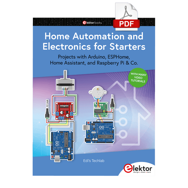
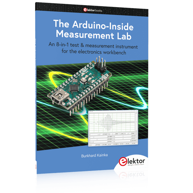
New Products
€ 269,00
Members € 242,10
€ 84,95
Members € 76,46
€ 139,95
Members € 125,96
€ 64,95
Members € 58,46


Bestsellers
€ 94,95€ 89,95
Members identical
€ 185,50€ 154,95
Members identical
€ 34,95
Members € 31,46
€ 39,95
Members € 31,96
€ 29,95
Members € 26,96


Deals
€ 449,00€ 299,00
Members identical
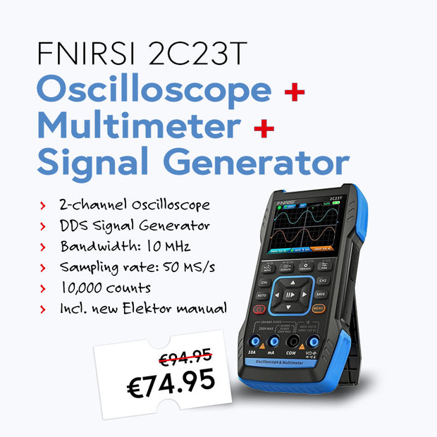
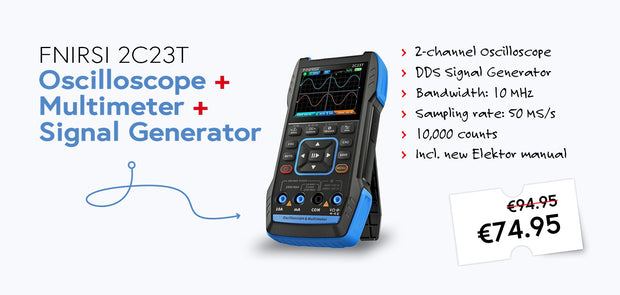
€ 89,95€ 74,95
Members identical
€ 79,95€ 59,95
Members identical
€ 44,95€ 29,95
Members identical
€ 69,95€ 34,95
Members identical


Collections
Elektor Products
€ 39,95€ 29,95
Members identical
€ 34,95
Members € 31,46
-
€ 29,95
Members € 26,96

€ 10,95
Members € 9,86
-
€ 34,95
Members € 31,46


Top Brands


Reviews
-
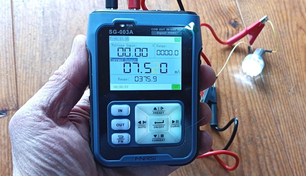
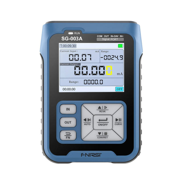
by Clemens Valens FNIRSI SG-003A Signal Generator
The FNIRSI SG-003A Multi-Functional Signal Generator is a kind of process meter for generating and measuring voltages, currents, and frequencies compatible with PLCs and other...
-
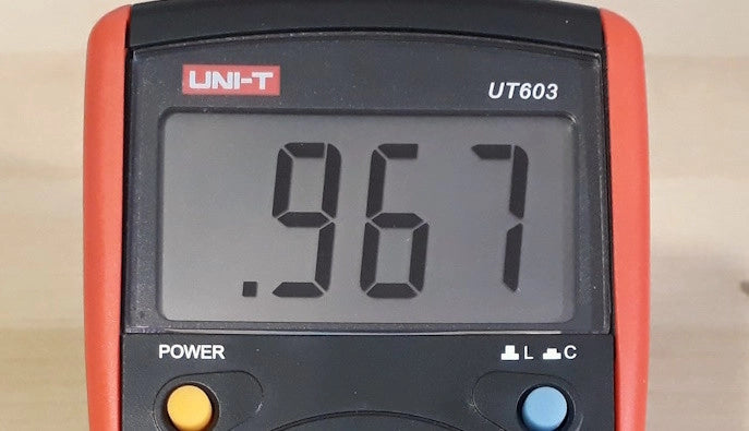
by Jean-François Simon LCR Meter: The UNI-T UT603 (Review)
Looking for a portable LCR meter? Check out the features and uses for the UNI-T UT603 LCR meter in our detailed review!
-
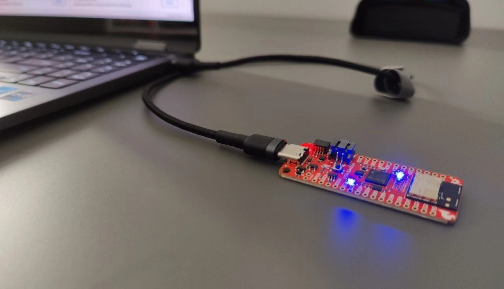
by Saad Imtiaz SparkFun Thing Plus Matter (MGM240P): A Versatile Matter-Based IoT Development Board (Review)
The SparkFun Thing Plus Matter (MGM240P) is a versatile and feature-rich development board designed for creating Matter-based IoT devices. Matter, formerly known as Project CHIP...
-
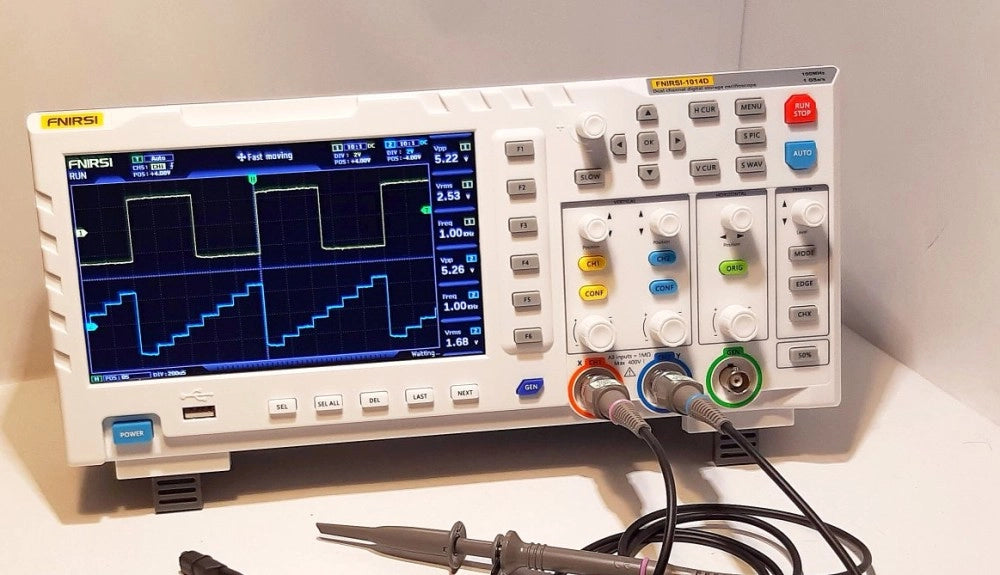
by Günter Spanner FNIRSI 1014D Digital Storage Oscilloscope: Good Performance for Tight Budgets
For activities such as tinkering with amplifiers, sensors, and microcontrollers like Arduinos, ESPs, Raspberry Pis, or repairing consumer electronics, a 100 MHz bandwidth and two...


