
Search results for "labnation"
-

JOY-iT JOY-iT PS1440-C-Pro Programmable Laboratory Power Supply with RS485 (1440 W)
With the JOY-iT PS1440-C-Pro, you get a programmable laboratory power supply that delivers DC voltages ranging from 0.01 to 60 V and DC currents from 0.01 to 24 A at the voltage output. The intuitive control panel allows you to program, store, and recall up to 9 different DC voltage settings. You can also configure individual protection and limiting functions—such as overvoltage protection. All settings are easily adjusted via the keypad and/or rotary control and are clearly shown on the high-resolution 2.4" color display. For enhanced connectivity, the PS1440-C-Pro includes an RS485 interface for robust, long-distance communication. This makes it ideal for complex setups where signal stability, noise immunity, and reliable data transfer are critical. The included connector ensures a secure connection, improving the overall reliability and performance of your laboratory equipment setup. Features Complete device ready for immediate use RS485 interface Battery charging function Values can be entered conveniently via keypad Over current & over voltage protection adjustable Integrated RTC, NTC temperature sensor Included detailed documentation in English, German & French Specifications Input voltage 230 V Output voltage 060 V Output current 0-24 A Output power 0-1440 W Input voltage accuracy ±1% +5 digits Output voltage accuracy ±0.3% +3 digits Output current accuracy ±0.5% +5 digits Battery voltage ±0.5% +3 digits Input voltage measurement resolution 0.01 V Output voltage measurement resolution 0.01 V Current measurement resolution 0.01 V Battery voltage measurement resolution 0.01 V Response time in constant voltage mode 2 ms @ 0.1-5 A Load regulation in constant voltage mode ±0.1% +2 digits Load regulation in constant current mode ±0.1% +3 digits Measuring range electric charge 0-9999.99 Ah Measuring range energy 0-9999.99 Wh Statistical errors in electric charge & energy ±2% Output ripple 100 mV VPP @ 12 V150 mV VPP @ 24 V Sensor temperature detection range −10~100°C (0-200°F) Sensor temperature detection accuracy ±3°C (±6°F) Working mode Step-down operation Screen brightness setting Level 0-5, 6 levels in total Permissible working temperature −10~40°C (0-104°F) Dimensions 170 x 93 x 340 mm Included JOY-iT PS1440-C Power Supply 2-pin connector for RS485 interface Power cord Manual Downloads Datasheet MODBUS Protocol PC Software Driver for Windows
€ 499,00
Members: € 449,10
-

Elektor Labs Elektor Low-Noise Lab Power Supply
The Elektor Low-Noise Lab Power Supply is a fully analogue, adjustable, medium-power symmetrical bench supply that contains no switching or digital components. It provides an output voltage adjustable between 0 V and ±22 V, and an output current adjustable from 0 A to 1 A. Because it avoids any form of switching circuitry, the design delivers extremely low noise. To display both output voltages and currents, four miniature moving-coil panel meters are used. Most modern laboratory power supplies and AC adapters employ switch-mode techniques. Even the best examples inevitably exhibit high-frequency ripple and other switching artefacts on their output, which can interfere with the testing of sensitive analogue circuits and disturb low-level measurements. To overcome this, the concept here is a completely analogue power supply. Although less efficient than its switch-mode counterparts, the reduced efficiency is of little importance for test-bench use and ensures cleaner, more reliable measurement results. Because many analogue circuits require a symmetrical supply, this design delivers positive and negative output voltages of equal magnitude. A small amount of adjustment is available to compensate for any imbalance. Naturally, a variable current-limit function is also included. The kit includes the components required to build the power supply, except for the transformers. Specifications Output Voltage 0…+22 V, 0, −22 V Output Current 0…+1 A, 0…−1 A Noise −85 dBV, (at 0.95 A/20 V, B = 22 kHz) −84 dBV (at 0.95 A/20 V, B > 500 kHz) Ripple 50 µVRMS (at 950 mA/20 V, B = 22 kHz, mainly 100 Hz component) Included 3x PCBs: Regulator (PCB-1), Mains Filter (PCB-2) and Transformer (PCB-3) All the components except the AC transformers 4x moving-coil meters Additional parts for wiring (wires, banana sockets, IEC Power entry module, etc.) Not included The three AC transformers An enclosure Parts List For the Regulator PCB (240386-1) Resistors (250 mW, 1%) R1 = 12 Ω R2, R8, R37, R62 = 1 MΩ R3, R7, R10, R13, R17, R20, R22, R30, R35, R42, R45, R47, R55, R60 = 100 Ω, 600 mW R4, R5 = 4.7 kΩ R6 = 100 kΩ R9, R12, R14, R36, R38, R39, R61, R63, R66, R72, R78, R79 = 10.0 kΩ, 600 mW R11 = 9.76 kΩ, 600 mW R15, R40 = 44.2 kΩ, 600 mW R16, R41, R77 = 1 kΩ R18, R43 = 1.5 kΩ, 1 W, 5% R19, R44 = 470 Ω, 1 W, 5% R21, R46 = 330 Ω, 600 mW R23, R24, R48, R49 = 1.0 Ω, 1 W R25, R50 = 1 kΩ, 1 W, 5% R26, R28, R51, R53 = 1.000 kΩ 0.1%, 15 ppm/C R27, R29, R52, R54 = 10.00 kΩ 0.1%, 15 ppm/C R31, R56 = 1.2 kΩ, 1 W, 5% R32, R57 = 47 kΩ R33, R58 = 270 Ω R34, R59 = 27 kΩ R64, R69 = 12.0 kΩ R65 = 3.0 kΩ, 600 mW R67, R80 = 470 Ω, 600 mW R68, R70 = 6.8 kΩ, 600 mW R71 = 30.0 kΩ,, 600 mW R73, R74, R75, R76 = 10 MΩ P1, P2, P3 = 10 kΩ, 200 mW, 20%, potentiometer, 1 turns, single, lin., panel mount P4, P5 = 500 Ω, 500 mW, 10%, trimmer, 25 turns, 3296Y-1-501LF Bourns P6, P7 = 10 kΩ, 500 mW, 10%, trimmer, 25 turns, 3296Y-1-501LF Bourns Capacitors C1 = 100 nF, 50 V, 10%, ceramic X7R, LS 5 mm C2, C3, C6, C7, C30 = 10 µF, 63V, 20%, LS 2.5 mm, 3000hours@105°C C4, C5, C8, C9, C13, C14, C18, C19, C23, C24, C28, C29, C31, C32, C38, C39 = 100 nF, 250 V, 10%, PET, LS 7.5 mm C10, C20 = 47 nF, 100 V, 5%, PET, LS 5 mm C11, C21 = 10 nF, 100 V, 5%, PET, LS 5 mm C12, C22 = 220 µF, 35 V, 20%, 0.024 Ω, LS2.5/3.5 mm, Ir 3.4 A, 2000hours@125°C, polymer C15, C25 = 120 µF, 50 V, 20%, ESR 0.02 Ω, Diam. 10 mm max., LS 5 mm C16, C26 = 15 nF, 100 V, 5%, PET, LS 5 mm C17, C27 = 47 nF, 100 V, 5%, PET, LS 5 mm C33, C34 = 22 µF, 50 V, 20%, LS 2 mm, 10000 hours @ 105°C C35, C36, C44, C45 = 1 µF, 100 V, 10%, LS 5 mm, ceramic X7R C37 = 100 uF, 50 V, 20%. LS 3.5 mm C40, C41, C42, C43, C46, C47, C48, C49 = 1000 µF, 50 V, 20%, LS 5/7.5 mm, Ir 3.32 A, 10000hours@105°C, D 16 mm C50, C51, C52, C53 = 47 nF, 100 V, 10%, ceramic X7R, LS 5 mm Inductors L1, L2 = 4.7 µH, 3.2 A, 0.033 Ω, LS 5 mm, RLB0914-4R7ML Bourns L3 = Commom mode choke, 14.5 mH, 3 A, SSRH24NH-30145 Kemet Semiconductors D1, D2, D3, D4, D5, D9, D10, D11, D15 = BAT85, DO-34 D6, D7, D12, D13 = SR560, DO-201AD D8, D14, D16 = 1N4148, DO-35 D17 = Zenerdiode, 5.6 V, 0.5 W, DO-41 D18, D19 = 1N4004, DO-41 D20, D21 D22, D23 = V30100CI-M3/P, dual common cathode, TO-220 D24 = Zener diode, 30 V, 1 W, DO-41 LED1, LED2 = LED, red, T-1 (3 mm) LED3, LED4 = LED, green, T-1 (3 mm) TVS1, TVS2 = BZW50-33B, R6 T1, T2, T4 = BC337.25, TO-92 T3 = NJW0302G, TO-3P T5, T6, T8 = BC327.25, TO-92 T7 = NJW0281G, TO-3P T9 = BD139, TO-126 (SOT-32) IC1 = LM334Z, TO-92 IC2 = LM4040AIZ-5.0/NOPB, TO-92 (TO-226AA-3) IC3, IC4 = OPA2992IDR, SOIC-8 IC5, IC6 = OPA4992IDR, SOIC-14 IC7 = OPA992IDBVR, SOT-23-5 IC8 = LM339N, DIP-14 IC9 = LM317, TO-220 IC10 = LM337, TO-220 Others F1, F2 = 5×20 mm fuse, 1.6 A, fast acting HS1, HS2 = Heatsink MC33271 (for T3/T7), 2.7°C/W, PCB mount, height 63.5 mm K1, K4 = 3-way screw terminal block, LS 3.5 mm, max. 1.5 mm² K2, K3 = 3-way screw terminal block, LS 3.5 mm, max. 1 mm² M1, M3 = Moving coil meter, Range 30 V, type 91C4, 45×45 mm M2, M4 = Moving coil meter, Range 1 A, type 91C4, 45×45 mm² RE1 = Relay DPDT,5V, UA2-5NU Miscellaneous 3× 3-way screw terminal block, LS 3.5 mm, max. 1 mm² (for P1, P2, P3) 4× Pin header, 1×2, vertical, pitch 2.54 mm (for LED1, LED2, LED3, LED4) 4× Pin socket, 1×2, vertical. pitch 2.54 mm (for LED1, LED2, LED3, LED4) 2× Heatsink FK222SA220, 20°C/W, PCB mount (for IC9 & IC10) 2× Mica thermal pad for TO-220, 12×18×0.05 mm (for IC9 & IC10) 2× Insulating bushing IB 6, TO-220 (for IC9 & IC10) 2× Ceramic thermal pad, 23×20×2 mm (for T3 & T7) 2× PCB Fuse Holder, for 5×20 mm fuse, 10 A (for F1, F2) 2× Cover for PCB Fuse Holder, transparent (for F1, F2) 2× 2-way screw terminal block, LS 3.5 mm, max. 1 mm² (for M1 & M3) 2× 2-way screw terminal block, LS 3.5 mm, max. 1.5 mm² (for M2 & M4) 8× M3 solder lug, thickness 0.35 mm (for M1…M4) M4 solder lug, thickness 0.35 mm (to connect 4 mm banana connectors) Screened cable, 1 pair, 2×24 AWG/0.22 mm², 1 m (for P1, P2 & P3) IC socket, DIP, 14 contacts (for IC8) M3 washer, plain, steel M3 screw, 16 mm, steel, pan head M3 nut M3 spring washer 50 mm M3 standoff, steel, male-female 12 mm M3 standoff, steel, male-female 10 mm M3 standoff, steel, male-female M3 screw, 8 mm, steel, pan head For the Mains Fiter PCB (240386-2) Resistor R1 = 220 kΩ, 1 W, 500 V, 5% Capacitors C1, C2 = 470 nF, 305 VAC, Class X2, 11 × 27 mm max., LS 15/22.5 mm C3, C4, C5, C6 = 2.2 nF, 300 VAC, Class Y2, 13 × 4 mm, LS 10 mm, PP Inductors L1, L2 = Common-mode choke, 6.8 mH, 1.7 A, TDK B82732R2172B030 Semiconductor MOV1 = TVS varistor, 300 VAC, S14K300 (230 VAC, B72214S0301K101) and SK14K150 (150 VAC, B72214S0151K101) Others K1, K2 = 3-way screw terminal block, LS 7.62 mm F1 = Time-delay fuse, 0.5 A (230 VAC) or 1 A (115 VAC) Miscellaneous 1× Fuse holder, 5×20 mm, 10 A, 500 VAC 1× Transparent fuse cover 4× 10 mm M3 standoff, steel, male–female 4× M3 screw, 8 mm, steel, pan head 4× M3 nut For the Transformer PCB (240386-3) Resistors R1, R2 = 2.7 kΩ, 600 mW, 1% R3 = 10.0 kΩ, 600 mW, 1% Capacitor C1 = 220 µF, 50 V, 20%, Ø10 mm, LS 5 mm, 4000 h @ 105°C Transformers (not included in this kit!) TR1, TR2, TR3 = 2×7 V, 25 VA, PCB-mounted toroid, 70060K Talema Semiconductors D1–D4 = 1N4148, DO-35 D5, D6 = 1N4004, DO-41 D7 = Zener 5.6 V, 1.3 W, DO-41 LED1 = LED, red, T-1 (3 mm) IC1, IC2 = MOC8021M, CTR ≥ 1000%, DIP-6 Others F1, F2, F3 = 160 mA time-delay fuse (230 VAC) or 315 mA time-delay fuse (115 VAC) K1 = 2-way screw terminal block, LS 7.62 mm K2 = 3-way screw terminal block, LS 3.5 mm, max 1.5 mm² K3, K4 = 3-way screw terminal block, LS 3.5 mm, max 1 mm² RE1, RE2 = Relay DPDT, 5 A/250 VAC / 24 VDC Miscellaneaous 1× Pin header 1×2, pitch 2.54 mm + matching socket for LED1 3× Fuse holder 5 × 20 mm, 10 A, 500 VAC + transparent cover 3× M4 screw, 8 mm, pan head + washer for TR1-TR3 8× M3 screw, 8 mm, pan head + nut + washer 8× 10 mm M3 standoff, steel, male–female 2× IC socket, DIP-6 for IC1 & IC2 Additional Parts 1 m red insulated wire, stranded, 1.5 mm² 0.5 m blue insulated wire, stranded, 1.5 mm² 0.5 m black insulated wire, stranded, 1.5 mm², 0.5 m 2 m red insulated wire, stranded, D 0.56 mm (0.25 mm²) 2 m black insulated wire, stranded, D 0.56 mm (0.25 mm²) 0.5 m Multicore Cable, Flexible, 3 Core, 0.75 mm² (24 x 0.2 mm) Red banana socket Black banana socket Blue banana socket Green banana socket IEC Power Entry Module with switch, IEC C14 3 crimp terminals, FASTON, 4.75 x 0.81 mm 3 knobs Links Elektor Labs JumpStarter Page Article (Part 1) Article (Part 2)
€ 299,00€ 249,00Best Price
-
FNIRSI FNIRSI DPS150PD DC Power Supply (150 W)
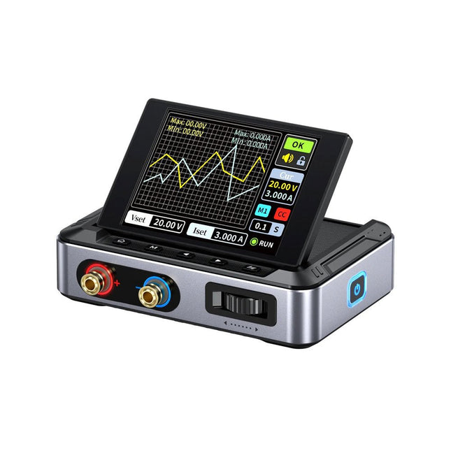
The FNIRSI DPS150 is a high-performance adjustable DC power supply that features a USB-C input interface and multiple power supply modes, allowing precise adjustment of output voltage (0-30 V) and current (0-5 A). It provides efficient, low-consumption, and stable output, equipped with multiple safety protection functions including overvoltage, overcurrent, overload, overheating, and reverse connection. It can be flexibly applied to serial connection of multiple devices, with rich and user-friendly display and operation, compact and portable design, meeting various application needs. Features 30 V, 5 A, 150 W variable DC power with 0.01 V, 0.001 A precision, CC/CV modes, and <20 mV ripple to protect sensitive electronics. Supports PC, QC, and DC inputs with programmable outputs and 6 preset voltage/current settings. Compatible with 4 mm banana plugs, U-shaped terminals, and copper wires for various equipment. 8 safety mechanisms including overvoltage, current, short circuit, and overheating protection. 2.8-inch HD IPS screen with 90° flip, numerical and curve displays for easy monitoring. Small, space-saving design for use in labs, repairs, and DIY projects. Specifications Input Voltage 5~32 V DC Input Current 100 mA-5 A Output Voltage 0-30 V Output Current 0~5 A Output Power 0-150 W Input Way PD fast charger QC fast charger Power bank DC power adapters Operating Environment 0-40°C Load Regulation 0.49% Full Load Efficiency 96.30% Display 2.8 inch (320 x 240) Dimensions 106 x 76 x 28 mm Weight 178 g Included 1x DPS150 Power Supply 2x Alligator clip wires (black & red) 1x C2C PD charging cable 1x 100 W PD GaN Adapter (EU) 1x Micro USB cable 1x Manual Downloads Manual Firmware V0.0.1
€ 95,00
-

LabNation LabNation SmartScope USB Oscilloscope
SmartScope is a compact 2-channel USB oscilloscope with a bandwidth of 30 MHz and a sampling rate of 2x 100 MSa/s. It is compatible with all major platforms, including Windows, macOS, Linux, and Android. The operation and display of measurement signals are done via smartphone, tablet, or PC. Additionally, a logic analyzer and a signal generator are integrated. Even more, you can get mobile with it: take the SmartScope on the road, thanks to the single-cable connectivity. Everything is going to be intuitive: pointing, pinching and swiping finally replaces the clunky interfaces of old scopes. With the SmartScope you develop your digital interfaces using the 100 MS/s logic analyzer. With this tool you can design any signal you want using Excel, then upload it to the built-in Arbitrary Waveform Generator (AWG). At the end capture the voltage at any point of your design at 100 million times each second. The Software for the support of Windows / macOS / Linux / Android and Export formats (Excel .csv / Matlab .mat) are given. Features Channel sampled at 100 MHz/s each AC/DC coupling on analog inputs 100% silent 64 Mbit RAM: x10000 zoom Arbitrary Waveform Generator 8 digital inputs at 100 MS/s each 4 digital outputs at 100 MS/s each Externally power your scope in case your mobile can't supply the juice. Specifications Oscilloscope Bandwidth 30 MHz (-3 dB point) Sample rate 2x 100 MS/s Channels 2 Max pre-trigger position 16x full scale Max post-trigger position Full scale Max full voltage scale 10 V/div (±35 V input range) Min full voltage scale 20 mV/div Analog input range -35 V, +35 V Max input peak-to-peak 40 V Signal coupling AC / DC Precision 8 bit Input impedance 1 MΩ // 10 pF Waverforms 200 waveforms/s Data delay to host < 10 ms Sample depth Up to 4 million samples per channel External trigger Yes Logic Analyzer Input channels 8 Input impedance 100 kOhm // 2 pF to GND Sample rate 100 MS/s Logic level 1.8 V to 5.0 V Diode protection Bidirectional Input data buffer 4 million samples Waverforms 200 waveforms/s Data delay to host < 10 ms Protocol decoders I²C, SPI, UART, I²S integrated User extensible Wave Generator (Analog Output) Output channels 1 Data rate Up to 50 MS/s Output level 0-3.3 V (Opamp driven) Output buffer Up to 2048 samples Max slew rate 30 ns/V Step 13 mV Wave Generator (Digital Output) Channels 4 Data rate Up to 100 MS/s Output level 3.3 V or 5 V (selectable) Output buffer Up to 2048 samples Diode protected Yes Programmable Logic USB controller MicroChip PIC18F14K50 USB interface PicKit3 or USB flashable FPGA Xilinx Spartan 6 FPGA interface JTAG and USB flashable Size & Weight Dimensions (L x W x D) 110 x 64 x 24.2 mm (4.33 x 2.52 x 0.95") Weight 158 g Case Aluminium Connectivity Device/Host mini USB included Record waveforms Store Matlab (.mat) or Excel (.csv) files through Dropbox Analog BNC 2 probes included Digital 8x 0.1" pitch, probes (included) Sync USB micro B-B Power USB micro B (optional) Included 1x SmartScope USB Oscilloscope 2x Analog probes 1x Digital probe cable 1x USB cable Downloads Software GitHub Wiki



