Search results for "joy OR it OR sensor OR kit OR x40"
-

JOY-iT JOY-iT PS1440-C-Pro Programmable Laboratory Power Supply with RS485 (1440 W)
With the JOY-iT PS1440-C-Pro, you get a programmable laboratory power supply that delivers DC voltages ranging from 0.01 to 60 V and DC currents from 0.01 to 24 A at the voltage output. The intuitive control panel allows you to program, store, and recall up to 9 different DC voltage settings. You can also configure individual protection and limiting functions—such as overvoltage protection. All settings are easily adjusted via the keypad and/or rotary control and are clearly shown on the high-resolution 2.4" color display. For enhanced connectivity, the PS1440-C-Pro includes an RS485 interface for robust, long-distance communication. This makes it ideal for complex setups where signal stability, noise immunity, and reliable data transfer are critical. The included connector ensures a secure connection, improving the overall reliability and performance of your laboratory equipment setup. Features Complete device ready for immediate use RS485 interface Battery charging function Values can be entered conveniently via keypad Over current & over voltage protection adjustable Integrated RTC, NTC temperature sensor Included detailed documentation in English, German & French Specifications Input voltage 230 V Output voltage 060 V Output current 0-24 A Output power 0-1440 W Input voltage accuracy ±1% +5 digits Output voltage accuracy ±0.3% +3 digits Output current accuracy ±0.5% +5 digits Battery voltage ±0.5% +3 digits Input voltage measurement resolution 0.01 V Output voltage measurement resolution 0.01 V Current measurement resolution 0.01 V Battery voltage measurement resolution 0.01 V Response time in constant voltage mode 2 ms @ 0.1-5 A Load regulation in constant voltage mode ±0.1% +2 digits Load regulation in constant current mode ±0.1% +3 digits Measuring range electric charge 0-9999.99 Ah Measuring range energy 0-9999.99 Wh Statistical errors in electric charge & energy ±2% Output ripple 100 mV VPP @ 12 V150 mV VPP @ 24 V Sensor temperature detection range −10~100°C (0-200°F) Sensor temperature detection accuracy ±3°C (±6°F) Working mode Step-down operation Screen brightness setting Level 0-5, 6 levels in total Permissible working temperature −10~40°C (0-104°F) Dimensions 170 x 93 x 340 mm Included JOY-iT PS1440-C Power Supply 2-pin connector for RS485 interface Power cord Manual Downloads Datasheet MODBUS Protocol PC Software Driver for Windows
€ 499,00
Members: € 449,10
-

JOY-iT Joy-Pi Advanced Development Platform (incl. Raspberry Pi 4, 8 GB)
For a limited time, the Joy-Pi Advanced is available in a great-value bundle with a Raspberry Pi 4 (8 GB)! The Joy-Pi Advanced is a compact and powerful device that allows you to realize your projects quickly and easily. Whether you already have a lot of experience, or next to none, the Joy-Pi Advanced lets you unleash your creativity. Thanks to its compatibility with a wide range of platforms, including Raspberry Pi, Raspberry Pi Pico, Arduino Nano, BBC micro:bit, and NodeMCU ESP32, you can easily and quickly access your preferred platform. In addition, the Joy-Pi Advanced features more than 30 stations, lessons, and modules, giving you an unlimited variety of ways to get your projects done. With the self-developed learning center, you can not only improve your skills but also create new projects. The learning center offers a wealth of information and tutorials that will guide you step by step through your projects. Joy-Pi Advanced is characterized in particular by its intelligent switch units, which allow an extended use of the available pins. A total of three switch units are integrated, each equipped with 12 individual switches that provide precise control of the connected sensors and modules. This system solves the well-known problem of limited pin count that occurs with conventional microcontrollers. The switch units allow you to operate a large number of sensors and modules in parallel by switching them on and off individually. This simulates multiple pin assignment, allowing you to exploit the full power of your projects without compromising functionality. By combining innovative adapter boards and the micro:bit slot, you can achieve seamless compatibility with a wide range of microcontrollers such as Raspberry Pi Pico, NodeMCU ESP32, micro:mit and Arduino Nano. The specially developed adapter boards are designed to perfectly match the respective microcontroller. By plugging the microcontroller onto the appropriate adapter board and then plugging it into the micro:bit slot, the Joy-Pi Advanced quickly and easily becomes compatible with the different microcontrollers. This allows seamless integration of your preferred platform and the ability to combine the strengths of the different microcontrollers in your projects. This way, you can fully focus on your creative projects without worrying about the compatibility of different microcontrollers. The Joy-Pi Advanced simplifies the development process and gives you the possibility to design your projects flexibly and individually. Features Highly integrated development platform & learning center Fast, easy & wireless combination of various sensors & actuators Installation option for Raspberry Pi 4 Compatible with various microcontrollers Self-developed, didactic learning platform for Raspberry Pi & Windows Specifications Compatible to Raspberry Pi 4, Arduino Nano, NodeMCU ESP32, BBC micro:bit, Raspberry Pi Pico Installed sensors, actuators & components 39 Learning platform Over 40 entries in the know-ledge database, 10 projects, 10 learning tasks, 14 visions Displays 7-segment display, 16x2 display, 1.8“ TFT display, 0.96" OLED display, 8x8 RGB matrix Sensors DS18B20, shock sensor, hall sensor, barometer, sound sensor, gyroscope, PIR sensor, Light barrier, NTC, Light sensor, 6x touch sensor, color sensor, ultrasonic distance sensor, DHT11 temperature & humidity sensor Control Joystick, 5x switches, potentiometer, rotary encoder, 4x4 button matrix, relays, PWM fan Motors Servo interface, Stepper motor interface, Vibration motor Measuring & conversion modules Analog-Digital Converter, Level converter, voltmeter, Variable voltage supply Other components RTC real time clock, buzzer, EEPROM memory, infrared receiver, breadboard, RFID reader Adapter boards Adapter for NodeMCU ESP32, Arduino Nano & Raspberry Pi Pico, Board connectors for Raspberry Pi & External Boards Electronic components Infrared remote control, RFID chip, RFID card, 6x alligator clips, microSD card reader, servo motor, stepper motor, 32 GB microSD card Components 40x resistors, 3x green LEDs, 3x yellow LEDs, 3x red LEDs, 1x transistor, 5x buttons, 1x potentiometer, 2x capacitors Other accessories Screw assortment, screwdriver, accessory storage bag, power supply & power cable, servo mount Power supply Built-in power supply: 36 W, 12 V, 3 A Case connector: Small device plug C8 Voltage outputs 12 V, 5 V, 3.3 V, Variable voltage output (2-11 V) Data buses & signal outputs I²C, SPI, Analog to digital converter Battery (RTC) CR2032 Dimensions 327 x 200 x 52 mm Included Raspberry Pi 4 (8 GB RAM) Downloads Joy-Pi website Datasheet Manual
€ 519,00€ 419,00
Best Price
-

Elektor Publishing Automotive Sensors and Actuators
Principles, Systems, and Electronics This handbook provides a detailed study of the sensors and actuators at the heart of modern vehicle electronics. It begins with basic electrical and electronic concepts, introducing the principles and terminology essential for understanding automotive systems. The book explores sensors and actuators on a system-by-system basis, including: Fundamentals of electrical engineering, electromagnetic phenomena, and motor principles Passive and active electronic components, integrated circuits, protection devices, and automotive-grade electronics Sensor characteristics, signal conditioning, ADCs, PWM and frequency outputs, and interface adaptation Automotive communication links and protocols, including LIN and SENT Engine sensors: air mass, pressure, temperature, speed, position, exhaust and emissions-related sensors Transmission sensors for manual and automatic systems Steering and suspension sensors for conventional and active systems Vehicle body and electrical system sensors for comfort, climate, access, and monitoring functions Engine actuators such as throttle bodies, injectors, turbo actuators, EGR systems, ignition components, and pumps Transmission, brake, steering, suspension, and body actuators Identification and coding of electronic components and packages commonly used in automotive applications The structure and operating principles of each component are explained, with relevant electronic circuitry illustrated. Its system-oriented organization and practical focus make it a valuable reference for understanding, testing, and troubleshooting automotive electronic systems.
€ 39,95
Members: € 35,96
-
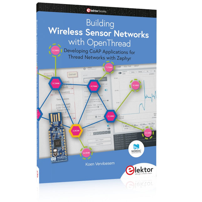
Elektor Publishing Building Wireless Sensor Networks with OpenThread
Developing CoAP applications for Thread networks with Zephyr This book will guide you through the operation of Thread, the setup of a Thread network, and the creation of your own Zephyr-based OpenThread applications to use it. You’ll acquire knowledge on: The capture of network packets on Thread networks using Wireshark and the nRF Sniffer for 802.15.4. Network simulation with the OpenThread Network Simulator. Connecting a Thread network to a non-Thread network using a Thread Border Router. The basics of Thread networking, including device roles and types, as well as the diverse types of unicast and multicast IPv6 addresses used in a Thread network. The mechanisms behind network discovery, DNS queries, NAT64, and multicast addresses. The process of joining a Thread network using network commissioning. CoAP servers and clients and their OpenThread API. Service registration and discovery. Securing CoAP messages with DTLS, using a pre-shared key or X.509 certificates. Investigating and optimizing a Thread device’s power consumption. Once you‘ve set up a Thread network with some devices and tried connecting and disconnecting them, you’ll have gained a good insight into the functionality of a Thread network, including its self-healing capabilities. After you’ve experimented with all code examples in this book, you’ll also have gained useful programming experience using the OpenThread API and CoAP.
€ 39,95
Members: € 35,96
-
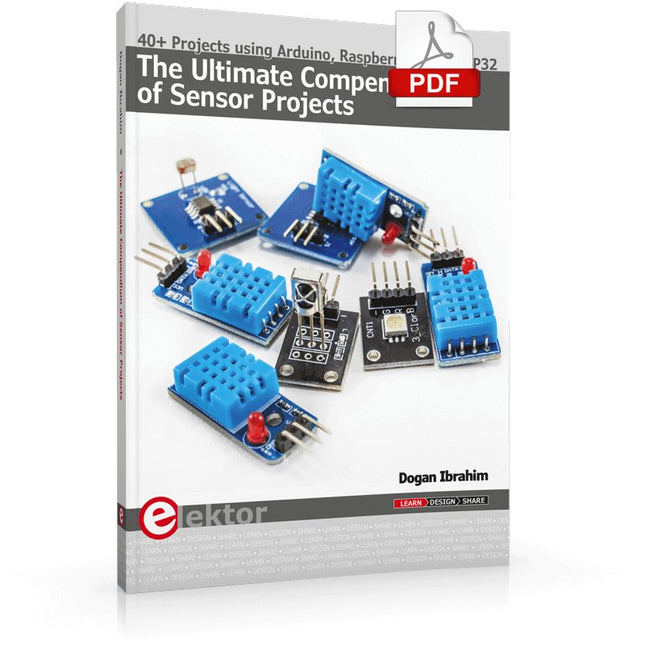
Elektor Digital The Ultimate Compendium of Sensor Projects (E-book)
40+ Projects using Arduino, Raspberry Pi and ESP32 This book is about developing projects using the sensor-modules with Arduino Uno, Raspberry Pi and ESP32 microcontroller development systems. More than 40 different sensors types are used in various projects in the book. The book explains in simple terms and with tested and fully working example projects, how to use the sensors in your project. The projects provided in the book include the following: Changing LED brightness RGB LEDs Creating rainbow colours Magic wand Silent door alarm Dark sensor with relay Secret key Magic light cup Decoding commercial IR handsets Controlling TV channels with IT sensors Target shooting detector Shock time duration measurement Ultrasonic reverse parking Toggle lights by clapping hands Playing melody Measuring magnetic field strength Joystick musical instrument Line tracking Displaying temperature Temperature ON/OFF control Mobile phone-based Wi-Fi projects Mobile phone-based Bluetooth projects Sending data to the Cloud The projects have been organized with increasing levels of difficulty. Readers are encouraged to tackle the projects in the order given. A specially prepared sensor kit is available from Elektor. With the help of this hardware, it should be easy and fun to build the projects in this book.
€ 34,95
Members: € 27,96
-

Elektor Digital Automotive Sensors and Actuators (E-book)
Principles, Systems, and Electronics This handbook provides a detailed study of the sensors and actuators at the heart of modern vehicle electronics. It begins with basic electrical and electronic concepts, introducing the principles and terminology essential for understanding automotive systems. The book explores sensors and actuators on a system-by-system basis, including: Fundamentals of electrical engineering, electromagnetic phenomena, and motor principles Passive and active electronic components, integrated circuits, protection devices, and automotive-grade electronics Sensor characteristics, signal conditioning, ADCs, PWM and frequency outputs, and interface adaptation Automotive communication links and protocols, including LIN and SENT Engine sensors: air mass, pressure, temperature, speed, position, exhaust and emissions-related sensors Transmission sensors for manual and automatic systems Steering and suspension sensors for conventional and active systems Vehicle body and electrical system sensors for comfort, climate, access, and monitoring functions Engine actuators such as throttle bodies, injectors, turbo actuators, EGR systems, ignition components, and pumps Transmission, brake, steering, suspension, and body actuators Identification and coding of electronic components and packages commonly used in automotive applications The structure and operating principles of each component are explained, with relevant electronic circuitry illustrated. Its system-oriented organization and practical focus make it a valuable reference for understanding, testing, and troubleshooting automotive electronic systems.
€ 32,95
Members: € 26,36
-

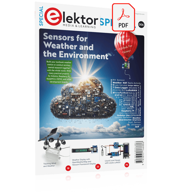
Elektor Special: Sensors for Weather and the Environment
Build your textbook weather station or conduct environmental research together with the whole world. With many practical projects for Arduino, Raspberry Pi, NodeMCU, ESP32, and other development boards. Weather stations have enjoyed great popularity for decades. Every current and even every long discontinued electronics magazine has regularly featured articles on building your own weather station. Over the years, they have become increasingly sophisticated and can now be fully integrated into an automated home — although this often requires loyalty to an (expensive) brand manufacturer across all components. With your own weather and environmental data, you can keep up and measure things that no commercial station can. It’s also fun: expand your knowledge of electronics, current microcontroller development boards and programming languages in a fun and meaningful way. For less than 10 euros you can get started and record your first environmental data — with time and growing interest, you will continue to expand your system. In this Edition Which Microcontroller Fits My Project? The Right Development Environment Tracking Wind and Weather Weather Display with OpenWeatherMap and Vacuum Fluorescent Display Volatile Organic Compounds in the Air We Breathe Working with MQ Sensors: Measuring Carbon Monoxide — Odorless but Toxic CO2 Traffic Light with ThingSpeak IoT Connection An Automatic Plant Watering System Good Indoor Climate: Temperature and Humidity are Important criteria Classy Thermometer with Vintage Tube Technology Nostalgic Weather House for the Whole Family Measuring Air Pressure and Temperature Accurately Sunburn Warning Device DIY Sensor for Sunshine Duration Simple Smartphone Says: Fog or Clear View? Identifying Earthquakes Liquid Level Measurement for Vessels and Reservoirs Water pH Value Measurement Detecting Radioactive Radiation GPS: Sensor Location Service Across the Globe Saving and Timestamping Log Files on SD Cards LoRaWAN, The Things Network, and ThingSpeak Operating a LoRaWAN Gateway for TTN Defying "Wind and Weather" Mega Display with Weather Forecasz
€ 19,95
Members: € 17,96
-

Elektor Digital Building Wireless Sensor Networks with OpenThread (E-book)
Developing CoAP applications for Thread networks with Zephyr This book will guide you through the operation of Thread, the setup of a Thread network, and the creation of your own Zephyr-based OpenThread applications to use it. You’ll acquire knowledge on: The capture of network packets on Thread networks using Wireshark and the nRF Sniffer for 802.15.4. Network simulation with the OpenThread Network Simulator. Connecting a Thread network to a non-Thread network using a Thread Border Router. The basics of Thread networking, including device roles and types, as well as the diverse types of unicast and multicast IPv6 addresses used in a Thread network. The mechanisms behind network discovery, DNS queries, NAT64, and multicast addresses. The process of joining a Thread network using network commissioning. CoAP servers and clients and their OpenThread API. Service registration and discovery. Securing CoAP messages with DTLS, using a pre-shared key or X.509 certificates. Investigating and optimizing a Thread device’s power consumption. Once you‘ve set up a Thread network with some devices and tried connecting and disconnecting them, you’ll have gained a good insight into the functionality of a Thread network, including its self-healing capabilities. After you’ve experimented with all code examples in this book, you’ll also have gained useful programming experience using the OpenThread API and CoAP.
€ 32,95
Members: € 26,36
-
Elektor Digital Elektor Special: Sensors for Weather and the Environment (PDF)
Build your textbook weather station or conduct environmental research together with the whole world. With many practical projects for Arduino, Raspberry Pi, NodeMCU, ESP32, and other development boards. Weather stations have enjoyed great popularity for decades. Every current and even every long discontinued electronics magazine has regularly featured articles on building your own weather station. Over the years, they have become increasingly sophisticated and can now be fully integrated into an automated home — although this often requires loyalty to an (expensive) brand manufacturer across all components. With your own weather and environmental data, you can keep up and measure things that no commercial station can. It’s also fun: expand your knowledge of electronics, current microcontroller development boards and programming languages in a fun and meaningful way. For less than 10 euros you can get started and record your first environmental data — with time and growing interest, you will continue to expand your system. In this Edition Which Microcontroller Fits My Project? The Right Development Environment Tracking Wind and Weather Weather Display with OpenWeatherMap and Vacuum Fluorescent Display Volatile Organic Compounds in the Air We Breathe Working with MQ Sensors: Measuring Carbon Monoxide — Odorless but Toxic CO2 Traffic Light with ThingSpeak IoT Connection An Automatic Plant Watering System Good Indoor Climate: Temperature and Humidity are Important criteria Classy Thermometer with Vintage Tube Technology Nostalgic Weather House for the Whole Family Measuring Air Pressure and Temperature Accurately Sunburn Warning Device DIY Sensor for Sunshine Duration Simple Smartphone Says: Fog or Clear View? Identifying Earthquakes Liquid Level Measurement for Vessels and Reservoirs Water pH Value Measurement Detecting Radioactive Radiation GPS: Sensor Location Service Across the Globe Saving and Timestamping Log Files on SD Cards LoRaWAN, The Things Network, and ThingSpeak Operating a LoRaWAN Gateway for TTN Defying "Wind and Weather" Mega Display with Weather Forecasz
€ 14,95
Members: € 13,46


-
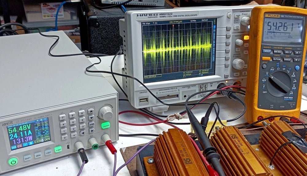
, by Clemens Valens Trying Out the Joy-it JT-PS1440-C 1.5 kW Power Supply (Review)
In today's high-powered world of e-bikes, electric scooters, and various other electronic vehicles, robust and adaptable power supplies are indispensable for motor testing and battery...
-
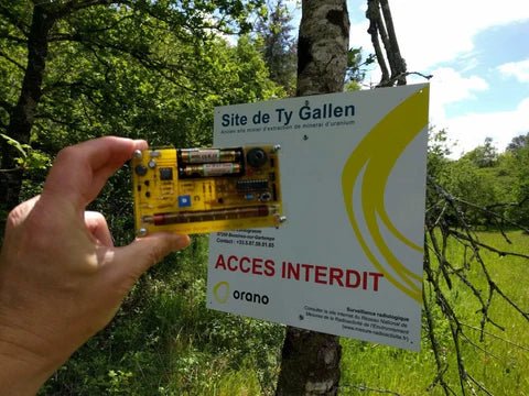
, by Clemens Valens Review: Detect Radiation with the MightyOhm Geiger Counter Kit
The MightyOhm Geiger Counter is a device for detecting beta and gamma radiation levels. Because radiation is so harmful, you may want to keep an...
-
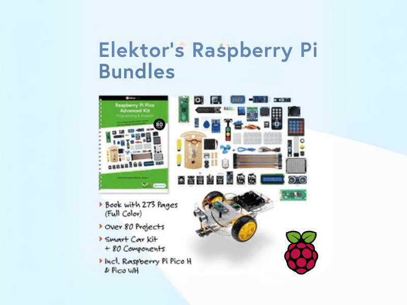
, by Lobna Belarbi Elektor’s Raspberry Pi Bundles: From Beginner-Friendly to Advanced Kits
Find the Perfect Raspberry Pi Bundle for Your Skill Level Whether you're a beginner eager to explore the world of Raspberry Pi or an advanced...


