65 jaargangen op USB – Nu incl. jaargang 2025!
NIEUW: Voor artikelen vanaf het jaar 2000 is er nu een aparte downloadoptie voor extra materiaal zoals PCB-layouts, Gerber-bestanden en software!
Deze USB-stick (64 GB) bevat de complete jaargangen 1961-2025 (alle nummers) van het elektronica-vakblad Elektor. Elektor wil mensen inspireren om zich elektronica en computertechniek eigen te maken door het presenteren van nabouwvriendelijke, professioneel ontworpen schakelingen op alle terreinen van de elektronica:
Audio & Video
Basiskennis
Computer & apparatuur
Hobby & modelbouw
Hoogfrequent
Huis & tuin
Meten & testen
Microcontrollers
Stroomvoorziening
Al dat andere dat niet zo gemakkelijk in een van deze categorieën kan worden ondergebracht.
De meer dan 15.000 afzonderlijke artikelen zijn chronologisch op publicatiedatum (maand/jaar) geordend.
Elektor GPT
Elektor GPT is een AI-aangedreven tool waarmee gebruikers door het decennialange Elektor-archief kunnen navigeren. Met behulp van geavanceerde zoekalgoritmen en natuurlijke taalverwerking vindt Elektor GPT snel artikelen, projecten en andere bronnen uit het archief.
Specificaties
Geheugen
64 GB
Connectoren
1x USB-A1x USB-C
Systeemeisen
Computer geschikt voor Adobe Reader vanaf versie 7
Webbrowser
48 années sur clé USB – Année 2025 incluse !
NOUVEAU : Pour les articles à partir de l’année 2000, une option de téléchargement séparée est désormais disponible pour des ressources supplémentaires telles que les plans de PCB, les fichiers Gerber et les logiciels !
Cette clé USB (64 Go) contient tous les numéros d’Elektor en français des années 1978 à 2025. Elektor propose à ses lecteurs des montages électroniques de conception professionnelle et aisément reproductibles, dans les domaines de l’électronique et de l’informatique appliquées. Il leur apporte également des informations sur l’évolution technologique et les nouveaux produits. Les principaux domaines d’application sont :
Alimentation
Audio, vidéo & HiFi
Auto, moto & vélo
Domestique
Expérimentation
Hautes-fréquences
Informations générales
Loisirs
Mesure
Microcontrôleurs & PC
Photographie
Plus de 10.000 articles d’Elektor sont réunis sur cette clé USB, présentés par ordre de parution (mois/année).
Elektor GPT
Elektor GPT est un outil basé sur l'IA qui aide les utilisateurs à naviguer dans les archives d'Elektor, vieilles de plusieurs décennies. Grâce à des algorithmes de recherche avancés et au traitement du langage naturel, Elektor GPT trouve rapidement des articles, des projets et d'autres ressources dans les archives.
Spécifications
Stockage
64 Go
Connecteurs
1x USB-A1x USB-C
Matériel et logiciel requis
Ordinateur avec Adobe Reader version 7 ou sup.
Navigateur Internet
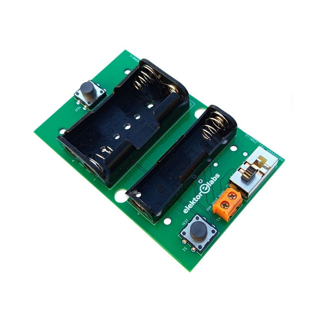
The Elektor Milliohmmeter Adapter uses the precision of a multimeter to measure very low resistance values. It is an adapter that converts a resistance into a voltage that can be measured with a standard multimeter.
The Elektor Milliohmmeter Adapter can measure resistances below 1 mΩ using a 4-wire (Kelvin) method. It is useful for locating short circuits on printed circuit boards (PCB).
The adapter features three measurement ranges – 1 mΩ, 10 mΩ, and 100 mΩ – selectable via a slide switch. It also includes onboard calibration resistors. The Elektor Milliohmmeter Adapter is powered by three 1.5 V AA batteries (not included).
Specifications
Measurement ranges
1 mΩ, 10 mΩ, 100 mΩ, 0.1%
Power supply
3x 1.5 V AA batteries (not included)
Dimensions
103 x 66 x 18 mm (compatible with Hammond 1593N-type enclosure, not included)
Special feature
On-board calibration resistors
Downloads
Documentation
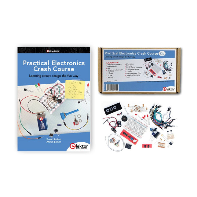
Getting started in electronics is not as difficult as you may think. With this bundle (book + kit of parts), you can explore and learn the most important electrical and electronics engineering concepts in a fun way by doing various experiments. You will learn electronics practically without getting into complex technical jargon and long calculations. As a result, you will be creating your own projects soon.
This kit contains the components required to build most of the detailed examples of the book on a breadboard and try them out for real.
The kit can, of course, also be used without the book for building other circuits and doing your own experiments.
Kit contents
1x 39 Ω, 1 W resistor
1x 47 Ω resistor
1x 180 Ω resistor
1x 330 Ω resistor
3x 1 kΩ resistor
1x 2.2 kΩ resistor
1x 3.9 kΩ resistor
1x 6.8 kΩ resistor
1x 10 kΩ resistor
1x 15 kΩ resistor
1x 22 kΩ resistor
1x 33 kΩ resistor
1x 47 kΩ resistor
1x 56 kΩ resistor
1x 82 kΩ resistor
1x 120 kΩ resistor
1x 680 kΩ resistor
2x 100 kΩ resistor
1x 10 kΩ trimmer
1x 10 kΩ linear potentiometer
1x 100 kΩ linear potentiometer
1x LDR
1x 1 nF ceramic capacitor
2x 10 nF ceramic capacitor
1x 100 nF ceramic capacitor
1x 1 µF, 25 V aluminium electrolytic capacitor
2x 10 µF, 25 V aluminium electrolytic capacitor
1x 100 µF, 25 V aluminium electrolytic capacitor
1x 470 µF, 25 V aluminium electrolytic capacitor
1x 1000 µF, 25 V aluminium electrolytic capacitor
1x RGB LED, Common-Cathode (CC)
1x 1N4148 small signal diode
1x 1N4733A 5.1 V, 1 W Zener diode
3x LED, red
2x BC337 NPN transistor
1x IRFZ44N N-channel MOSFET
2x NE555 timer
1x LM393 comparator
1x 74HCT08 quad AND gate
3x Tactile switch
2x SPDT switch
1x Relay, SPDT, 9 VDC
1x Active buzzer
1x Passive buzzer
50 cm Solid wire, 16 AWG, unjacketed
2x PP3 9 V battery clip
1x Breadboard
20x Jumper wire
This bundle contains:
Practical Electronics Crash Course Kit (valued at: €45)
Book: Practical Electronics Crash Course (normal price: €45)
The Elektor Zener Diode Tester is essentially a constant-current source that can be switched in steps from 1 to 50 mA. It can be used to test Z-diodes up to a maximum of 54 V. Thanks to a 60-V step-up converter, the device can be powered by the usual 5 to 12 V.
The principle of this tester is straightforward. A Z-diode or other DUT (device under test, such as an LED) is biased by an adjustable current source. The voltage across the DUT can be measured with a multimeter. The voltage of most (small) Z-diodes is specified at a current of 5 mA. Depending on the application, the voltage at other currents can also be of interest. That is why six current settings are available: 1, 2, 5, 10, 20, and 50 mA. LEDs are often specified at a current of 20 mA.
What can be tested is:
Whether a Z-diode is defective (short circuit or high impedance).
Whether a Z-diode exhibits the correct Z-voltage.
How a Z-voltage changes with different currents.
What exact voltage is present at an integrated voltage reference.
Whether LEDs in a series chain differ in brightness (hence the 20 mA current).
What the current gain is for different base currents in (power) transistors.
The kit contains all parts listed in the bill of materials including PCB and enclosure.
Specifications
Supply voltage
5…12 V/2 A (USB-C)
Supply current (Itest = 50 mA)
1.1 A @ 5 V / 412 mA @ 12 V
Selectable currents
1, 2, 5, 10, 20, and 50 mA
Max. test voltage
>54 V @ Itest ≥1 mA
Max. output voltage
60 V @ Itest = 0 mA
Voltage limit at 5 V
4.5 V @ Itest = 1 mA / 5.18 V @ Itest = 50 mA
Enclosure dimensions
110 x 82 x 44 mm
PCB size
105.4 x 67.3 mm
Connections
4 mm banana sockets for multimeter
2 mm banana sockets for test clips
USB-C socket for power supply
Included
Resistors
R1 = 3.3 kΩ, 600 mW, 1%
R2 = 0.15 Ω, 1 W, 5%, LS 12.7 mm, ø 3.5 mm
R3, R8 = 180 Ω, 600 mW, 1%
R4, R6, R16 = 1 kΩ, 600 mW, 1%
R5, R19 = 47 kΩ, 600 mW, 1%
R7 = 3.9 kΩ, 1 W, 5%, LS 12.7 mm, ø 3.5 mm
R9, R10, R12 = 10 kΩ, 600 mW, 1%
R11, R13 = 100 Ω, 600 mW 1%
R14 = 249 Ω, 600 mW, 1%
R15 = 499 Ω, 600 mW, 1%
R17 = 2.49 kΩ, 250 mW, 1%
R18 = 4.99 kΩ, 250 mW, 1%
Capacitors
C1 = 470 uF / 35 V, 20%, Ir = 1.86 A, ø 12.5 mm, LS 5 mm, ESR = 0.038 Ω (Panasonic EEUTP1V471)
C2 = 1 uF / 100 V, 10%, X7R, LS 5 mm
C3 = 2.2 nF / 50 V, 10%, X7R, LS 5 mm
C4, C7 = 100 nF / 100 V, 10%, X7R, LS 5 mm
C5 = 100 uF / 100 V, 20%, ø 14 mm max., LS 5 mm
C6 = 1 nF / 100 V, 10%, X7R, LS 5 mm
Inductor
L1 = 100 uH, Irms = 2.4 A, Isat = 3.5 A, 0.09 Ω, radial, pitch 2.5/5/10 mm, ø 14 mm max. (Kemet SBC8-101-242)
Semiconductors
D1 = MUR120G, DO-41
D2, D4 = STPS3150RL, DO-201AD
D3 = Z-diode, 18 V, 1.3 W (BZX85C18)
D5 = Z-diode, 5.1 V, 0.5 W (1N5231B)
LED1 = LED in pushbutton S1
LED2 = LED, green, 3 mm
IC1 = MC34063, DIP-8
IC2 = LM4040BIZ-5.0/NOPB, TO-92 (TO-226AA-3)
IC3 = TL051CP, DIP-8
T1 = BC327.25, TO-92
T2 = STP40NF10L, TO-220
T3 = IRF9510PBF, TO-220
T4 = 2N7000, TO-92
Others
K1, K2, S1, S3 = 2-way screw terminal block, LS 3.5 mm, max. 1.5 mm²
connected to K1 = USB-C socket, 30 V/3 A, chassis mounted, wired, 9 x 16 mm
connected to K2 = Banana Connector, 2 mm, Socket, 60 VDC, Panel Mount, red (Multicomp 24.102.1)
connected to K2 = Banana Connector, 2 mm, Socket, 60 VDC, Panel Mount, black (Multicomp 24.102.2)
Test clip, red, 30 VAC/60 VDC (Hirschmann 931467101)
Test clip, black, 30 VAC/60 VDC (Hirschmann 931467100)
S1 = Pushbutton, panel mount, SPST-NO, 30 DC/100 mA, with red LED
S2 = Rotary Switch, 6 position, 2 pole, 30°, 250 V/150 mA
S3 = Toggle switch, panel mount, SPDT, solder lugs, 28 VDC
T2, T3 = Heat sink, 15°C/W, FK 214 SA-CB
Enclosure Hammond 1591XXSSBK, ABS, 110 x 82 x 44 mm
Knob for S2, round shaft 6 mm, ø 21 mm, with indicator line (Multicomp CP-LB21-6-6D)
4 x Self-tapping screw #4-1/4", carbon steel, pan head
Banana plug, red, 2 mm, 60 VDC (Multicomp 25.205.1)
Banana plug, black, 2 mm, 60 VDC (Multicomp 25.205.2)
Banana socket, black 4 mm, panel mount
Banana socket, red 4 mm, panel mount
for LED1, LED2 = Pin header, 1 x 2, vertical, pitch 2.54 mm
for LED1, LED2 = Pin socket, 1 x 2, vertical, pitch 2.54 mm
for T2, T3 = M3 screw, 10 mm, steel, pan head
2 x M3 washer, plain, steel
4 x M3 nut
for IC1, IC3 = DIP-8 socket
Wire, black, 0.25 mm² (24 AWG), stranded 14 x 0.15 mm, 1 m
Wire, red, 0.25 mm² (24 AWG), stranded 14 x 0.15 mm, 1 m
PCB 250772-1 v1.1
Links
Article
Elektor Labs
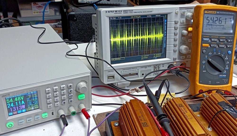
With the JOY-iT PS1440-C-Pro, you get a programmable laboratory power supply that delivers DC voltages ranging from 0.01 to 60 V and DC currents from 0.01 to 24 A at the voltage output.
The intuitive control panel allows you to program, store, and recall up to 9 different DC voltage settings. You can also configure individual protection and limiting functions—such as overvoltage protection. All settings are easily adjusted via the keypad and/or rotary control and are clearly shown on the high-resolution 2.4" color display.
For enhanced connectivity, the PS1440-C-Pro includes an RS485 interface for robust, long-distance communication. This makes it ideal for complex setups where signal stability, noise immunity, and reliable data transfer are critical. The included connector ensures a secure connection, improving the overall reliability and performance of your laboratory equipment setup.
Features
Complete device ready for immediate use
RS485 interface
Battery charging function
Values can be entered conveniently via keypad
Over current & over voltage protection adjustable
Integrated RTC, NTC temperature sensor
Included detailed documentation in English, German & French
Specifications
Input voltage
230 V
Output voltage
060 V
Output current
0-24 A
Output power
0-1440 W
Input voltage accuracy
±1% +5 digits
Output voltage accuracy
±0.3% +3 digits
Output current accuracy
±0.5% +5 digits
Battery voltage
±0.5% +3 digits
Input voltage measurement resolution
0.01 V
Output voltage measurement resolution
0.01 V
Current measurement resolution
0.01 V
Battery voltage measurement resolution
0.01 V
Response time in constant voltage mode
2 ms @ 0.1-5 A
Load regulation in constant voltage mode
±0.1% +2 digits
Load regulation in constant current mode
±0.1% +3 digits
Measuring range electric charge
0-9999.99 Ah
Measuring range energy
0-9999.99 Wh
Statistical errors in electric charge & energy
±2%
Output ripple
100 mV VPP @ 12 V150 mV VPP @ 24 V
Sensor temperature detection range
−10~100°C (0-200°F)
Sensor temperature detection accuracy
±3°C (±6°F)
Working mode
Step-down operation
Screen brightness setting
Level 0-5, 6 levels in total
Permissible working temperature
−10~40°C (0-104°F)
Dimensions
170 x 93 x 340 mm
Included
JOY-iT PS1440-C Power Supply
2-pin connector for RS485 interface
Power cord
Manual
Downloads
Datasheet
MODBUS Protocol
PC Software
Driver for Windows
More than 275 Power Supply Designs for Home Construction
This USB Stick contains over 275 different power supply circuits from the volumes 2001-2025 of Elektor. The article search feature allows you to search full-text content. The results are always displayed as pre-formatted PDF documents.
Highlights
Cuk Converter
Automatic Battery Switchover
Battery Voltage LED
Digital Benchtop Power Supply
Lithium-Ion Charger
Solar Cell Charger
Electronic Fuse
High Voltage Regulator
Power Supply for USB Devices
Step-up Converter for LEDs
Battery Management
and much more...
On the Stick you will also find a folder with additional material such as PCB layouts, Gerber files and software.
Specifications
Storage
16 GB
Interfaces
1x USB-A1x USB-C
System requirements
PC with Adobe Reader 7.0 or higher
Web browser
For a limited time, the Joy-Pi Advanced is available in a great-value bundle with a Raspberry Pi 4 (8 GB)!
The Joy-Pi Advanced is a compact and powerful device that allows you to realize your projects quickly and easily. Whether you already have a lot of experience, or next to none, the Joy-Pi Advanced lets you unleash your creativity. Thanks to its compatibility with a wide range of platforms, including Raspberry Pi, Raspberry Pi Pico, Arduino Nano, BBC micro:bit, and NodeMCU ESP32, you can easily and quickly access your preferred platform.
In addition, the Joy-Pi Advanced features more than 30 stations, lessons, and modules, giving you an unlimited variety of ways to get your projects done. With the self-developed learning center, you can not only improve your skills but also create new projects. The learning center offers a wealth of information and tutorials that will guide you step by step through your projects.
Joy-Pi Advanced is characterized in particular by its intelligent switch units, which allow an extended use of the available pins. A total of three switch units are integrated, each equipped with 12 individual switches that provide precise control of the connected sensors and modules. This system solves the well-known problem of limited pin count that occurs with conventional microcontrollers. The switch units allow you to operate a large number of sensors and modules in parallel by switching them on and off individually. This simulates multiple pin assignment, allowing you to exploit the full power of your projects without compromising functionality.
By combining innovative adapter boards and the micro:bit slot, you can achieve seamless compatibility with a wide range of microcontrollers such as Raspberry Pi Pico, NodeMCU ESP32, micro:mit and Arduino Nano. The specially developed adapter boards are designed to perfectly match the respective microcontroller. By plugging the microcontroller onto the appropriate adapter board and then plugging it into the micro:bit slot, the Joy-Pi Advanced quickly and easily becomes compatible with the different microcontrollers. This allows seamless integration of your preferred platform and the ability to combine the strengths of the different microcontrollers in your projects. This way, you can fully focus on your creative projects without worrying about the compatibility of different microcontrollers. The Joy-Pi Advanced simplifies the development process and gives you the possibility to design your projects flexibly and individually.
Features
Highly integrated development platform & learning center
Fast, easy & wireless combination of various sensors & actuators
Installation option for Raspberry Pi 4
Compatible with various microcontrollers
Self-developed, didactic learning platform for Raspberry Pi & Windows
Specifications
Compatible to
Raspberry Pi 4, Arduino Nano, NodeMCU ESP32, BBC micro:bit, Raspberry Pi Pico
Installed sensors, actuators & components
39
Learning platform
Over 40 entries in the know-ledge database, 10 projects, 10 learning tasks, 14 visions
Displays
7-segment display, 16x2 display, 1.8“ TFT display, 0.96" OLED display, 8x8 RGB matrix
Sensors
DS18B20, shock sensor, hall sensor, barometer, sound sensor, gyroscope, PIR sensor, Light barrier, NTC, Light sensor, 6x touch sensor, color sensor, ultrasonic distance sensor, DHT11 temperature & humidity sensor
Control
Joystick, 5x switches, potentiometer, rotary encoder, 4x4 button matrix, relays, PWM fan
Motors
Servo interface, Stepper motor interface, Vibration motor
Measuring & conversion modules
Analog-Digital Converter, Level converter, voltmeter, Variable voltage supply
Other components
RTC real time clock, buzzer, EEPROM memory, infrared receiver, breadboard, RFID reader
Adapter boards
Adapter for NodeMCU ESP32, Arduino Nano & Raspberry Pi Pico, Board connectors for Raspberry Pi & External Boards
Electronic components
Infrared remote control, RFID chip, RFID card, 6x alligator clips, microSD card reader, servo motor, stepper motor, 32 GB microSD card
Components
40x resistors, 3x green LEDs, 3x yellow LEDs, 3x red LEDs, 1x transistor, 5x buttons, 1x potentiometer, 2x capacitors
Other accessories
Screw assortment, screwdriver, accessory storage bag, power supply & power cable, servo mount
Power supply
Built-in power supply: 36 W, 12 V, 3 A Case connector: Small device plug C8
Voltage outputs
12 V, 5 V, 3.3 V, Variable voltage output (2-11 V)
Data buses & signal outputs
I²C, SPI, Analog to digital converter
Battery (RTC)
CR2032
Dimensions
327 x 200 x 52 mm
Included
Raspberry Pi 4 (8 GB RAM)
Downloads
Joy-Pi website
Datasheet
Manual
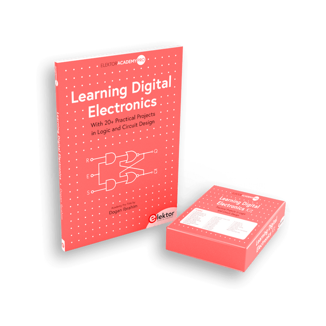
Master digital electronics – the hands-on way!
This bundle includes the book Learning Digital Electronics, featuring 20+ practical projects in Logic and Circuit design, as well as a 100-piece kit – so you can start building logic circuits, counters, displays, and more right away.
Learning Digital Electronics (Book)
This book is a practical guide to digital electronics, covering the essential components of modern digital systems: number systems, logic gates, Boolean algebra, combinational and sequential logic, and more.
Through more than 20 structured projects, you’ll design and build digital systems using real-world components such as logic gates, multiplexers, decoders, flip-flops, counters, and shift registers. The projects range from basic LED logic circuits to digital locks, display systems, traffic light controllers, and timing-based designs.
Selected projects introduce the use of tools such as CircuitVerse for circuit simulation, while several designs make use of 74HC-series logic devices, commonly used in digital hardware prototyping.
Inside, you’ll find:
Clear coverage of number systems and binary arithmetic
Logic gate fundamentals and universal gate implementations
Step-by-step projects using flip-flops, counters, and registers
Real-world design with 74HC-series logic chips
Techniques for designing combinational and sequential systems
This book takes a design-first, application-driven approach to digital electronics—built around working circuits, tested logic, and hands-on experimentation.
Learning Digital Electronics (Kit)
This kit has been specially developed to complement the book "Learning Digital Electronics". Since all necessary components are included, you can complete every practical project in the book directly.
Kit contents
2x 74HC08 AND gate chip
2x 74HC00 NAND gate chip
1x 74HC86 XOR gate chip
1x 555 timer chip
1x 74HC161 counter chip
1x 74HC164 shift register
1x CD4511 7-segment decoder
1x CD4027 JK flip-flop
1x BC337 NPN transistor
1x KPS-5161 7-segment common-cathode display
1x Light dependent resistor (LDR)
4x 10 KΩ resistors
8x 1 KΩ resistor
2x 47 KΩ resistors
1x 100 KΩ resistor
4x 2.7 KΩ resistors
1x 5.6 KΩ resistor
1x 150 KΩ resistor
1x 10 μF capacitor
2x 0.01 μF capacitor
2x 100 nF capacitor
8x Small red LED
1x Small green LED
1x Small orange LED
4x Pushbutton switches
1x Active buzzer
1x Battery holder for 3x AA batteries (batteries not included)
1x Breadboard
40x Male-to-male jumper wires (length: 200 mm)
With this 65 W USB-C PD power supply (with GaN technology) you can start using the FNIRSI HS-01 soldering iron straight away. Of course, you can also use this charger to fast charge your tablets and smartphones via USB-C and USB-A.
Included
65 W USB-C PD GaN Power Supply (EU)
,
by Clemens Valens
Trying Out the Joy-it JT-PS1440-C 1.5 kW Power Supply (Review)
In today's high-powered world of e-bikes, electric scooters, and various other electronic vehicles, robust and adaptable power supplies are indispensable for motor testing and battery...
,
by Jean-François Simon
Fnirsi FNB58 USB Tester (Review)
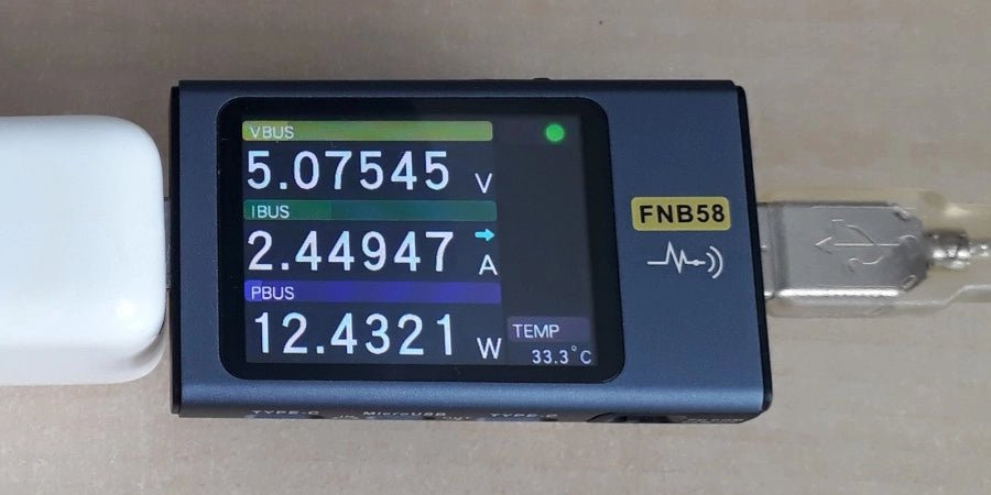
The Fnirsi FNB58 is a versatile USB tester capable of performing a wide array of voltage, current, and energy measurements, as well as supporting numerous...