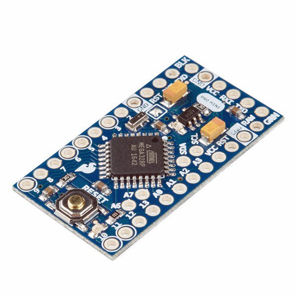
The Arduino Pro Mini is a microcontroller board based on the ATmega328P.
It has 14 digital input/output pins (of which 6 can be used as PWM outputs), 6 analog inputs, an on-board resonator, a reset button, and holes for mounting pin headers. A six pin header can be connected to an FTDI cable or SparkFun breakout board to provide USB power and communication to the board.
The Arduino Pro Mini is intended for semi-permanent installation in objects or exhibitions. The board comes without pre-mounted headers, allowing the use of various types of connectors or direct soldering of wires. The pin layout is compatible with the Arduino Mini.
The Arduino Pro Mini was designed and is manufactured by SparkFun Electronics.
Specifications
Microcontroller
ATmega328P
Board Power Supply
5-12 V
Circuit Operating Voltage
5 V
Digital I/O Pins
14
PWM Pins
6
UART
1
SPI
1
I²C
1
Analog Input Pins
6
External Interrupts
2
DC Current per I/O Pin
40 mA
Flash Memory
32 KB of which 2 KB used by bootloader
SRAM
2 KB
EEPROM
1 KB
Clock Speed
16 MHz
Dimensions
18 x 33.3 mm (0.7 x 1.3")
Downloads
Eagle files
Schematics
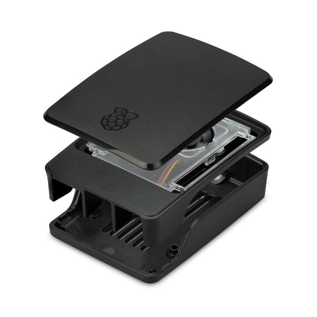
The Raspberry Pi 5 case is a refinement of the Raspberry Pi 4 case with improved thermal features to support the higher peak power consumption of the Raspberry Pi 5. It integrates a variable speed fan that is powered and controlled via a dedicated connector on the Raspberry Pi 5.
Pull Down Lever For Highest Score!
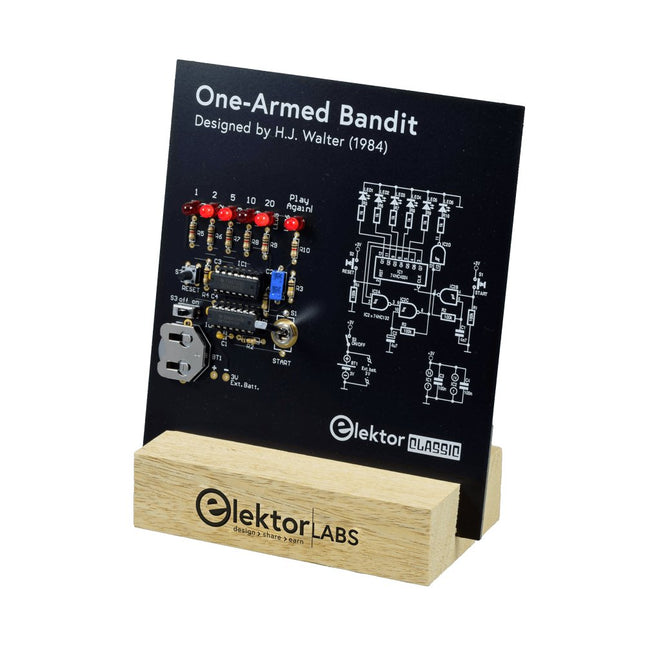
This Elektor Circuit Classic from 1984 shows a playful application of CMOS 400x series logic ICs in combination with LEDs, a highly popular combination at the time. The project imitates a spinning-digit type slot machine.
The Game
To play the game, first agree on the number of rounds. Player 1 actuates the switch lever as long as desired and releases it. The LEDs then show the score which is the sum of the 50-20-10-5 digits lit up. If the Play Again! LED lights, Player 1 has another, “free” round. If not, it’s Player 2’s turn. The players keep tab of their scores, and the highest score wins.
Features
LEDs Indicate Score
Multi-Player and Play Again!
Elektor Heritage Circuit Symbols
Tried & Tested by Elektor Labs
Educational & Geeky Project
Through-Hole Parts Only
Included
Printed Circuit Board
All Components
Wooden Stand
Bill of Materials
Resistors (5%, 250 mW)
R1,R2,R3,R4 = 100kΩ
R5,R6,R7,R8,R9,R10 = 1kΩ
Capacitors
C1 = 4.7nF, 10%, 50V, 5mm
C2 = 4.7μF, 10%, 63V, axial
C3,C4 = 100nF, 10 %, 50V, ceramic X7R, 5mm
Semiconductors
LED1-LED6 = red, 5mm (T1 3/4)
IC1 = 74HC4024
IC2 = 74HC132
Miscellaneous
S1 = switch, toggle, 21mm lever, SPDT, momentary
S2 = switch, tactile, 24V, 50mA, 6x6mm
S3 = switch, slide, SPDT
IC1,IC2 = IC socket, DIP14
BT1 = PCB-mount CR2032 battery retainer clip
Desktop Stand
PCB 230098-1
Not included: BT1 = CR2032 coin cell battery
The Raspberry Pi Bumper is a snap-on silicone cover that protects the bottom and edges of the Raspberry Pi 5.
Features
One-piece flexible silicone rubber bumper
Enables easy access to the power button
Mounting holes remain accessible underneath the bumper
Downloads
Datasheet
Specifications
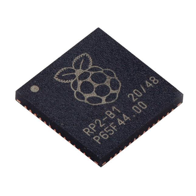
Dual ARM Cortex-M0+ @ 133 MHz
264 kB on-chip SRAM in six independent banks
Support for up to 16 MB of off-chip Flash memory via dedicated QSPI bus
DMA controller
Fully-connected AHB crossbar
Interpolator and integer divider peripherals
On-chip programmable LDO to generate core voltage
2x on-chip PLLs to generate USB and core clocks
30x GPIO pins, 4 of which can be used as analogue inputs
Peripherals
2x UARTs
2x SPI controllers
2x I²C controllers
16x PWM channels
USB 1.1 controller and PHY, with host and device support
8x PIO state machines
What you'll get
10x bare RP2040 chips
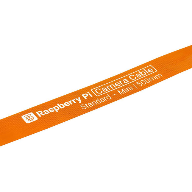
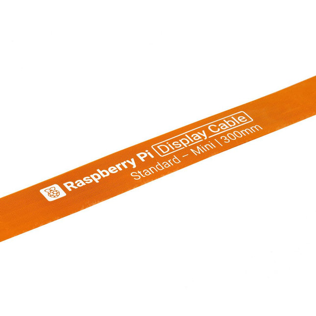
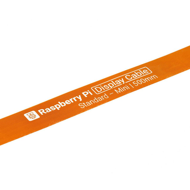
Raspberry Pi 5 provides two four-lane MIPI connectors, each of which can support either a camera or a display. These connectors use the same 22-way, 0.5 mm-pitch “mini” FPC format as the Compute Module Development Kit, and require adapter cables to connect to the 15-way, 1 mm-pitch “standard” format connectors on current Raspbery Pi camera and display products.These mini-to-standard adapter cables for cameras and displays (note that a camera cable should not be used with a display, and vice versa) are available in 200 mm, 300 mm and 500 mm lengths.
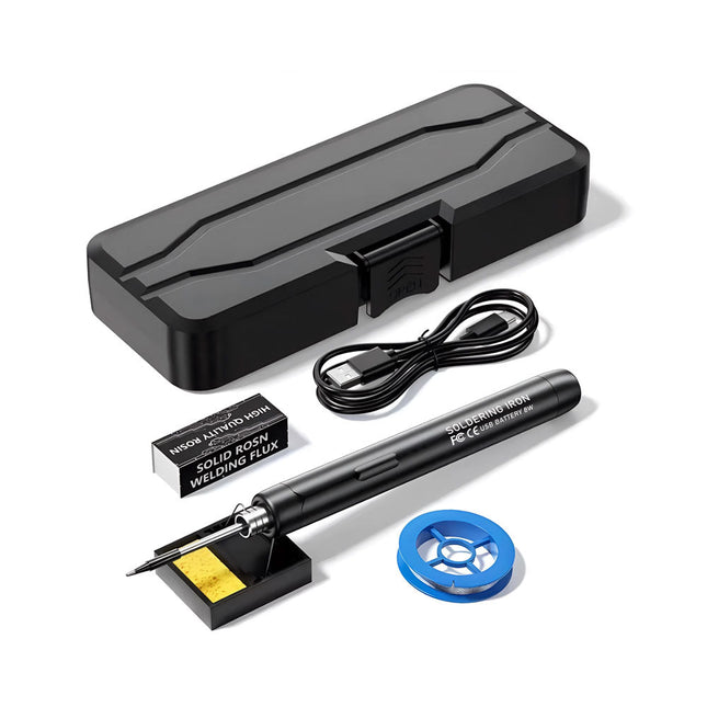
The Smart USB Soldering Iron Kit is a compact, cordless solution designed for precision and portability. Featuring intelligent three-speed temperature control (300-450°C) with an easy-to-read LED display, it heats up in just 10 seconds and melts solder in as little as 6 seconds.
The 1000 mAh rechargeable battery delivers up to 30 minutes of continuous use, making it ideal for quick repairs, electronics projects, and DIY tasks. With a plug-and-play, replaceable tip and a high-temperature-resistant insulated shell, it’s safe, user-friendly, and perfect for both beginners and professionals on the go.
Features
Three-Speed Intelligent Temperature Adjustment: Features an LED display screen with adjustable temperatures between 300-450°C (572-842°F). Easily switch between Celsius and Fahrenheit.
Integrated Plug-In Soldering Iron Tip: Plug-and-play design. The tip can be replaced by simply unscrewing it, ensuring quick and convenient operation.
Safe and Durable Design: High-temperature-resistant, insulated shell for enhanced safety during use.
Battery Capacity: Equipped with a rechargeable 1000 mAh battery that supports up to 30 minutes of continuous operation on a full charge – ideal for everyday tasks.
Efficient Performance: 8 W power with an integrated heating core for rapid heat-up. Melts tin in just 6 seconds, providing excellent thermal conductivity.
Easy to Use: After powering on via USB, set your desired temperature. The soldering iron heats up in 10 seconds. Once finished, place the tip on the stand—it cools down within 1 minute. Perfect for beginners, hobbyists, basic home repairs, and training engineers.
Cordless Innovation: This cordless soldering kit includes a built-in rechargeable lithium-ion battery, eliminating the need for cables. Versatile use for circuit board soldering, electrical repairs, jewelry making, metal crafts, computer maintenance, and DIY projects.
Specifications
Adjustable Temperature: 300-450°C (572-842°F)
Tin Melting Time: <15 seconds
Working Voltage: 5 V
Power Output: 8 W
Battery Capacity: 1000 mAh
Auto Sleep Function: Activates after 10 minutes of inactivity
Charging Time: Approx. 90 minutes
Battery Life: Up to 30 minutes continuous use
Charging Interface: USB-C
Main Material: Aluminum alloy
Dimensions: 190 x 16 mm (7.4 x 0.6")
Included
1x USB Soldering Iron
1x Soldering Tip
1x Soldering Rosin
1x Soldering Iron Holder (with Sponge)
1x USB-C Charging Cable
1x Solder Wire
1x Storage Box
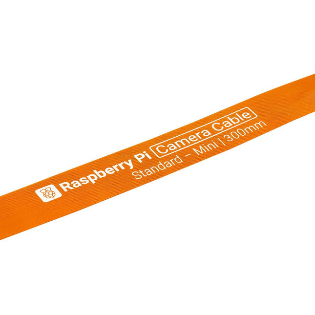
Raspberry Pi 5 provides two four-lane MIPI connectors, each of which can support either a camera or a display. These connectors use the same 22-way, 0.5 mm-pitch “mini” FPC format as the Compute Module Development Kit, and require adapter cables to connect to the 15-way, 1 mm-pitch “standard” format connectors on current Raspbery Pi camera and display products.These mini-to-standard adapter cables for cameras and displays (note that a camera cable should not be used with a display, and vice versa) are available in 200 mm, 300 mm and 500 mm lengths.
Features
Build in USB to Serial interface
Build-in PCB antenna
Powered by Pineseed BL602 SoC using Pinenut model: 12S stamp
2 MB Flash
USB-C connection
Suitable to breadboard BIY project
On board three color LEDs output
Dimensions: 25.4 x 44.0 mm
Note: USB cable is not included.
Raspberry Pi 5 provides two four-lane MIPI connectors, each of which can support either a camera or a display. These connectors use the same 22-way, 0.5 mm-pitch “mini” FPC format as the Compute Module Development Kit, and require adapter cables to connect to the 15-way, 1 mm-pitch “standard” format connectors on current Raspbery Pi camera and display products.These mini-to-standard adapter cables for cameras and displays (note that a camera cable should not be used with a display, and vice versa) are available in 200 mm, 300 mm and 500 mm lengths.
Raspberry Pi 5 provides two four-lane MIPI connectors, each of which can support either a camera or a display. These connectors use the same 22-way, 0.5 mm-pitch “mini” FPC format as the Compute Module Development Kit, and require adapter cables to connect to the 15-way, 1 mm-pitch “standard” format connectors on current Raspbery Pi camera and display products.These mini-to-standard adapter cables for cameras and displays (note that a camera cable should not be used with a display, and vice versa) are available in 200 mm, 300 mm and 500 mm lengths.