Master digital electronics – the hands-on way!
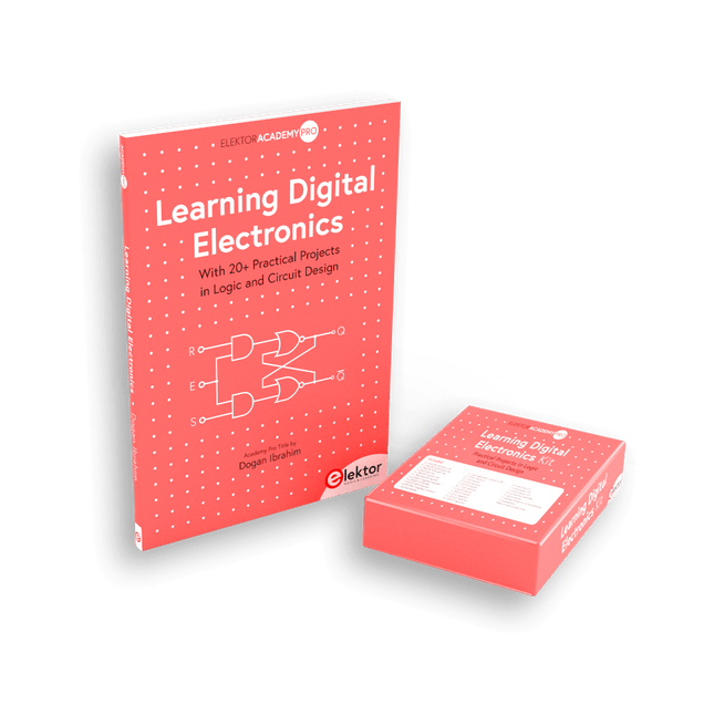
This bundle includes the book Learning Digital Electronics, featuring 20+ practical projects in Logic and Circuit design, as well as a 100-piece kit – so you can start building logic circuits, counters, displays, and more right away.
Learning Digital Electronics (Book)
This book is a practical guide to digital electronics, covering the essential components of modern digital systems: number systems, logic gates, Boolean algebra, combinational and sequential logic, and more.
Through more than 20 structured projects, you’ll design and build digital systems using real-world components such as logic gates, multiplexers, decoders, flip-flops, counters, and shift registers. The projects range from basic LED logic circuits to digital locks, display systems, traffic light controllers, and timing-based designs.
Selected projects introduce the use of tools such as CircuitVerse for circuit simulation, while several designs make use of 74HC-series logic devices, commonly used in digital hardware prototyping.
Inside, you’ll find:
Clear coverage of number systems and binary arithmetic
Logic gate fundamentals and universal gate implementations
Step-by-step projects using flip-flops, counters, and registers
Real-world design with 74HC-series logic chips
Techniques for designing combinational and sequential systems
This book takes a design-first, application-driven approach to digital electronics—built around working circuits, tested logic, and hands-on experimentation.
Learning Digital Electronics (Kit)
This kit has been specially developed to complement the book "Learning Digital Electronics". Since all necessary components are included, you can complete every practical project in the book directly.
Kit contents
2x 74HC08 AND gate chip
2x 74HC00 NAND gate chip
1x 74HC86 XOR gate chip
1x 555 timer chip
1x 74HC161 counter chip
1x 74HC164 shift register
1x CD4511 7-segment decoder
1x CD4027 JK flip-flop
1x BC337 NPN transistor
1x KPS-5161 7-segment common-cathode display
1x Light dependent resistor (LDR)
4x 10 KΩ resistors
8x 1 KΩ resistor
2x 47 KΩ resistors
1x 100 KΩ resistor
4x 2.7 KΩ resistors
1x 5.6 KΩ resistor
1x 150 KΩ resistor
1x 10 μF capacitor
2x 0.01 μF capacitor
2x 100 nF capacitor
8x Small red LED
1x Small green LED
1x Small orange LED
4x Pushbutton switches
1x Active buzzer
1x Battery holder for 3x AA batteries (batteries not included)
1x Breadboard
40x Male-to-male jumper wires (length: 200 mm)
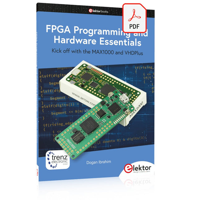
Kick off with the MAX1000 and VHDPlus
Ready to Master FPGA Programming? In this guide, we’re diving into the world of Field Programmable Gate Arrays (FPGAs) – a configurable integrated circuit that can be programmed after manufacturing. Imagine bringing your ideas to life, from simple projects to complete microcontroller systems!
Meet the MAX1000: a compact and budget-friendly FPGA development board packed with features like memory, user LEDs, push-buttons, and flexible I/O ports. It’s the ideal starting point for anyone wanting to learn about FPGAs and Hardware Description Languages (HDLs).
In this book, you’ll get hands-on with the VHDPlus programming language – a simpler version of VHDL. We’ll work on practical projects using the MAX1000, helping you gain the skills and confidence to unleash your creativity.
Get ready for an exciting journey! You’ll explore a variety of projects that highlight the true power of FPGAs. Let’s turn your ideas into reality and embark on your FPGA adventure – your journey starts now!
Exciting Projects You’ll Find in This Book
Arduino-Driven BCD to 7-Segment Display Decoder
Use an Arduino Uno R4 to supply BCD data to the decoder, counting from 0 to 9 with a one-second delay
Multiplexed 4-Digit Event Counter
Create an event counter that displays the total count on a 4-digit display, incrementing with each button press
PWM Waveform with Fixed Duty Cycle
Generate a PWM waveform at 1 kHz with a fixed duty cycle of 50%
Ultrasonic Distance Measurement
Measure distances using an ultrasonic sensor, displaying the results on a 4-digit 7-segment LED
Electronic Lock
Build a simple electronic lock using combinational logic gates with push buttons and an LED output
Temperature Sensor
Monitor ambient temperature with a TMP36 sensor and display the readings on a 7-segment LED
Downloads
Software
This complete ESP32 microcontroller programming course features a textbook, a component kit, hands-on projects, and a comprehensive online course with simulations. It is ideal for step-by-step learning of embedded systems programming with Arduino using a practical, hands-on approach.
A Practical Introduction to Embedded Systems with the ESP32
This course is designed for people who are new to embedded systems and looking for a structured, example-driven way to get started.
A kit of parts comprising LEDs and resistors, switches, sensors and actuators, displays, a breadboard and wires, and more is included. These are used in the course to illustrate example applications.
No prior experience with Arduino or embedded development is required. Each section features hands-on examples and mini projects designed to reinforce key concepts and inspire deeper exploration. By the end of the course, you’ll be able not only to reproduce the examples but also to build on them with your own ideas and applications.
What Will You Learn?
Microcontroller programming with the ESP32 using the Arduino IDE
Working with Digital I/O, read buttons and encoders, control LEDs and relays
Read analog inputs, voltages, and analog sensors
Generating analog output signals and PWM
Use serial communication like UART, I²C and SPI to control displays and read digital sensors and SD cards
Managing time
Working with interrupts
Real-time sensor input and control via buttons, LEDs, and displays
Control actuators like relays and servo motors
Who Is It For?
Students and self-learners exploring embedded systems
Makers and IoT enthusiasts looking to improve their hardware skills
Educators and trainers seeking ready-to-teach material
What's Inside the Box?
Access to the full course on the Elektor Academy Pro Learning Platform
ESP32 microcontroller board + USB cable
Book: Programming Microcontrollers in C/C++ Using Arduino
Downloadable project files for every module
Component Box:
2× LED, red, 5 mm
LED, green, 5 mm
3× Resistor, 470 Ω, 0.25 W
LDR
Potentiometer, 10 kΩ, linear
Pushbutton
Rotary encoder module
Relay module
DHT22 Humidity & Temperature Sensor
TM1637-compatible 4-digit 7-segment display
MPU-6050 IMU with headers
SSD1306-compatible I²C OLED display
Micro SD card adapter with header
Buzzer
SG90 Micro Servo
ILI9341-compatible SPI 240×320 TFT display
20× Jumper wires
Breadboard
All Programming Courses (and differences in content)
Course
Arduino
Raspberry Pi Pico with Arduino C/C++
ESP32 with Arduino C/C++
Raspberry Pi Pico with MicroPython
ESP32 with MicroPython
Online Course
Access to Arduino Course
Access to Pico with Arduino C/C++ Course
Access to ESP32 with Arduino C/C++ Course
Access to Pico with MicroPython Course
Access to ESP32 with MicroPython Course
Board
Uno R3
Raspberry Pi Pico
ESP32
Raspberry Pi Pico
ESP32
Book
Programming Microcontrollers in C/C++ Using Arduino
Programming Microcontrollers in C/C++ Using Arduino
Programming Microcontrollers in C/C++ Using Arduino
Programming Microcontrollers in MicroPython
Programming Microcontrollers in MicroPython
Kit
40-piece Component Box
40-piece Component Box
40-piece Component Box
40-piece Component Box
40-piece Component Box
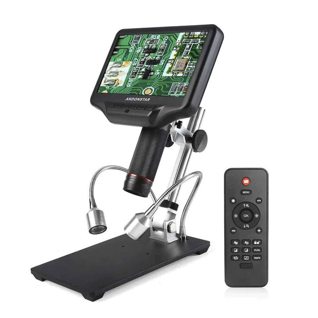
Examine your circuits with high precision and solder even the smallest SMDs and elements without any hassle.
Features
Multifunctional HDMI Digital Microscope features Full HD, comfortable headroom, improved ergonomy, multiple output signals with different resolutions.
Tilt angle of the wide LCD monitor is adjustable.
Comes with remote control.
Can be used as stand-alone.
Specifications
Screen size
7 inch (17.8 cm)
Image sensor
4 MP
Video output
UHD 2880x2160 (24fps)FHD 1920x1080 (60fps/30fps)HD 1280x720 (120fps)
Video format
MP4
Magnification
Up to 270 times (27 inch HDMI monitor)
Photo resolution
Max. 12 MP (4032x3024)
Photo format
JPG
Focus range
Min. 5 cm
Frame rate
Max. 120fps (under 600 Lux Brightness & HDP120)
Video interface
HDMI
Storage
microSD card (up to 32 GB)
Power source
5 V DC
Light source
2 LEDs with the stand
Stand size
20 x 12 x 19 cm
Included
1x Andonstar AD407 Digital Microscope
1x Metal stand with 2 LEDs
1x Optical bracket
1x UV filter
1x IR remote
1x Switch cable
1x Power adapter
1x HDMI cable
2x Screws
1x Screwdriver
1x User manual
Downloads
Manual
Model Comparison
AD407
AD407 Pro
AD409
AD409 Pro-ES
Screen size
7 inch (17.8 cm)
7 inch (17.8 cm)
10.1 inch (25.7 cm)
10.1 inch (25.7 cm)
Image sensor
4 MP
4 MP
4 MP
4 MP
Video output
2160p
2160p
2160p
2160p
Interfaces
HDMI
HDMI
USB, HDMI, WiFi
USB, HDMI, WiFi
Video format
MP4
MP4
MP4
MP4
Magnification
Up to 270x
Up to 270x
Up to 300x
Up to 300x
Photo resolution
Max. 4032x3024
Max. 4032x3024
Max. 4032x3024
Max. 4032x3024
Photo format
JPG
JPG
JPG
JPG
Focus distance
Min. 5 cm
Min. 5 cm
Min. 5 cm
Min. 5 cm
Frame rate
Max. 120f/s
Max. 120f/s
Max. 120f/s
Max. 120f/s
Storage
microSD card
microSD card
microSD card
microSD card
PC support
No
No
Windows
Windows
Mobile connection
No
No
WiFi + Measurement
WiFi + Measurement
Power source
5 V DC
5 V DC
5 V DC
5 V DC
Light source
2 LEDs with the stand
2 LEDs with the stand
2 LEDs with the stand
2 LEDs with the stand
Endoscope
No
No
No
Yes
Stand size
20 x 12 x 19 cm
20 x 18 x 32 cm
18 x 20 x 30 cm
18 x 20 x 32 cm
Weight
1.6 kg
2.1 kg
2.2 kg
2.5 kg
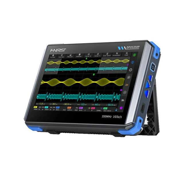
2 Channels • 350 MHz • 1 GSa/s • 50,000 wfm/s • 7 inch Touchscreen
The FNIRSI DPOS350P is a sleek 4-in-1 powerhouse in tablet form! This compact and portable device packs serious functionality: it combines a 2-channel oscilloscope (350 MHz), a signal generator (50 MHz), a frequency response analyzer (50 MHz), and a spectrum analyzer (200 kHz–350 MHz) – all in one unit.
Whether you're in R&D, troubleshooting, or field testing, the DPOS350P delivers the tools you need to measure, generate, analyze, and visualize electronic signals with precision and clarity. Its responsive high-resolution touchscreen and intuitive controls make signal analysis fast, flexible and efficient.
Features
Powerful Multi-Function Integration
350 MHz 2-channel oscilloscope with 1 GSa/s real-time sampling
50 MHz signal generator with 14 standard + custom waveforms
Spectrum analyzer (200 kHz–350 MHz): Perfect for EMI, RF & HF testing
Frequency response analyzer (FRA) up to 50 MHz
High-Performance Waveform Capture
50,000 wfm/s refresh rate for real-time signal clarity
350 MHz bandwidth (single-channel mode)
Detects rare and low-probability anomalies
Crisp Display & Smooth Operation
7" IPS touchscreen (1024 x 600 resolution)
Switch between grayscale and color temperature display
Easy to operate in various test environments
Reliable, Protected & Fast-Charging
High-voltage protection up to 400 V
Fast charging with QC 18 W (full charge in 2 hours)
Built for stable long-term operation
Data Storage & Export
Save up to 500 waveform records + 90 screenshots
USB export for easy reporting and offline analysis
Specifications
General
Display
7 inch (IPS full viewing angle)
Resolution
1024 x 600 pixels
Interaction mode
Capacitive touch screen
Total power consumption
10 W
Power-on configuration
5 presets
Charging
QC 18 W, 12 V/1.5 A (USB-C)
Battery
3.7 V, 8000 mAh lithium battery
Battery life
approx. 3 hours in operation, 5 hours standby
Heat dissipation
Air cooling
Expansion interface
USB data port
Automatic shutdown
15~60 minutes / off
Firmware upgrade
Support .iso image upgrade
Languages
English / Portuguese / Russian / Chinese
Dimensions
190 x 128 x 37 mm
Oscilloscope
Analog channels
2
Analog bandwidth
350 MHz
Rise time
1ns
Real-time sampling rate
1 GSa/s
Memory depth
60 Kpts
Input impedance
1 MΩ / 14PF
Time base range
5ns ~ 50s
Roll time base
50ms ~ 50s
Vertical sensitivity
2 mV ~ 20 V (1X)
Vertical range
16 mV ~ 160 V (1X)
DC accuracy
±2%
Time accuracy
±0.01%
Input coupling
DC / AC
Probe attenuation
1X / 10X / 100X
Hardware bandwidth limit
150M / 20M
High resolution mode
8bit ~ 16bit
Parameter measurements
12 types
Cursor measurement
Time, period, frequency, level, voltage
Trigger detection
Digital trigger
Trigger channel
CH1 / CH2
Trigger mode
Auto / Single / Normal
Trigger edge
Rising edge / Falling edge
Trigger suppression
L1 ~ L3
Trigger level
Manual / automatic 10% ~ 90%
Screenshot storage
90 pictures
Waveform storage
500 groups
Background grid
Display / hide
Waveform movement
Coarse adjustment / fine adjustment
Overvoltage protection
Withstand voltage 400 V
Waveform brightness
Adjustable
Simple FFT display
Yes
Digital fluorescence
Yes
Color temperature display
Yes
X-Y mode
Yes
ZOOM time base
Yes
One-key automatic adjustment
Yes
One-key return to zero
Yes
Data browser
Yes
Signal Generator
Waveform types
14 standard functions + captured waveform
Frequency
0~50 MHz (sine wave only, other waveforms up to 10M/5M/3M)
Amplitude
0~5 VPP
Offset
-2.5 V ~ +2.5V
Duty cycle
0.1~99.9%
Frequency resolution
1 Hz
Amplitude resolution
1 mV
Offset resolution
1 mV
Duty cycle resolution
0.1%
Customizable captured waveform
500 groups
Frequency Response Analyzer (FRA)
Excitation signal frequency
100 Hz ~ 50 MHz
Excitation signal amplitude
0~5 VPP
Excitation signal offset
-2.5V ~ +2.5V
Excitation frequency count
20~500
Cursor measurement
Frequency / gain / phase
Operating mode
Single / cyclic
System calibration
Yes
Spectrum Analyzer
Conversion method
FFT
FFT length
4K ~ 32K
Frequency range
200 KHz ~ 350 MHz
Level range
-60 dBmV ~ +260 dBmV
Cursor measurement
Frequency / amplitude
Marking parameter
Maximum energy harmonic
Waterfall chart
Yes
3D waterfall chart
Yes
Automatic adjustment
Yes
System calibration
Yes
Included
1x FNIRSI DPOS350P Oscilloscope (4-in-1)
2x 350 MHz Probes
1x QC 18 W Fast Charger (EU)
1x USB-C Cable
1x Alligator Clip
1x Storage Bag
1x Manual
Downloads
Manual
Firmware
This bundle is all about designing projects based on the 555 timer IC. The book features over 45 fully tested and documented projects. Together with the kit, which contains more than 130 through-hole components, you can build all the projects described on a breadboard. The setup also makes it easy to modify and experiment with the projects.
Over 45 Builds for the Legendary 555 Chip (and the 556, 558)
Some of the projects in the book are:
Alternately Flashing Two LEDs
Changing LED Flashing Rate
Touch Sensor On/Off Switch
Switch On/Off Delay
Light-Dependent Sound
Dark/Light Switch
Tone Burst Generator
Long Duration Timer
Chasing LEDs
LED Roulette Game
Traffic Lights
Continuity Tester
Electronic Lock
Switch Contact Debouncing
Toy Electronic Organ
Multiple Sensor Alarm System
Metronome
Voltage Multipliers
Electronic Dice
7-Segment Display Counter
Motor Control
7-Segment Display Dice
Electronic Siren
Various Other Projects
Kit Contents
Resistors
1x 15 kΩ
1x 68 kΩ
2x 47 kΩ
1x 82 kΩ
2x 820 Ω
1x 8.2 kΩ
3x 10 kΩ
1x 1.8 kΩ
1x 6.8 kΩ
14x 2.2 kΩ
10x 680 Ω
1x 27 kΩ
1x 5.6 kΩ
1x 560 kΩ
1x 4.7 kΩ
1x 3.3 kΩ
3x 33 kΩ
1x 36 kΩ
2x 100 kΩ
5x 1 kΩ
1x 3.9 kΩ
2x 56 kΩ
2x 12 kΩ
1x 10 kΩ potentiometer
1x 1 MΩ potentiometer
2x 50 kΩ potentiometer
3x 20 kΩ potentiometer
1x 10 kΩ potentiometer
1x 10 kΩ potentiometer
1x 50 kΩ potentiometer
1x 100 kΩ potentiometer
1x 50 kΩ potentiometer
Capacitors
1x 0.33 μF
1x 1 μF
1x 10 nF
1x 22 nF
1x 47 nF
1x 100 nF
1x 10 μF electrolytic
1x 33 μF electrolytic
2x 100 μF electrolytic
LEDs
10x 5 mm red LED
10x 3 mm red LED
3x 3 mm yellow LED
3x 3 mm green LED
1x Common-cathode 7-segment LED
Semiconductors
3x 555 timer
1x CD4017 counter
1x CD4026 counter
1x CD4011 NAND gate
4x 1N4148 diode
1x IRFZ46N MOSFET
1x Thermistor
1x Light dependent resistor (LDR)
Miscellaneous
1x Passive buzzer
1x Active buzzer
1x SG90 servo
1x 8 Ω mini loudspeaker
1x 9 V DC brushed motor
1x 5 V relay
1x 9 V battery clip
7x Pushbutton switches
1x Breadboard
1x Breadboard jumper wires
The XIAO ESP32-C3 board combines the ultra-compact form factor of the XIAO series with the full capabilities of the ESP32-C3 chip, including integrated Wi-Fi and Bluetooth 5.0. This book is a comprehensive, hands-on guide to getting the most out of this powerful yet affordable development board.
The author takes readers from the fundamentals to advanced projects. Starting with LED blinking and dimming, the book progresses to ADC and PWM for precise sensor interfacing and PWM-controlled lighting effects before moving on to building practical, real-world applications, including:
A Wi-Fi weather station with an OLED display and real-time online weather data
An ultrasonic parking assistant with audible feedback
A refrigerator monitoring probe with climate sensing and Deep Sleep for years of battery operation
A retro Pong game controlled by a touch-free sensor
A microphone-based party app that responds to claps
And much more: lighting control, reaction-time measurement, mains frequency analysis, soil moisture sensing, ambient LED lighting, and 7-segment displays
The OWON SDS1102 is an affordable benchtop digital oscilloscope that combines solid performance with essential measurement features. This 2-channel oscilloscope offers a 100 MHz bandwidth, a 1 GS/s sampling rate, a 7-inch LCD display, and a 10 kpts memory depth, making it a practical choice for everyday electronics testing, troubleshooting, and education.
The SDS1102 features a simplified trigger system with level and edge triggering, making it easy to capture and analyze common signals. It is designed for applications that do not require deep memory or advanced trigger functions, offering a straightforward and cost-effective solution for basic signal analysis.
Features
Bandwidth: 100 MHz
2 channels
Sample rate: 1 GS/s
Ultra-thin body
7-inch high-res LCD
SCPI and LabVIEW supported
Specifications
Bandwidth
100 MHz
Horizontal Scale (s/div)
5 ns/div – 1000 s/div
Channel
2
Vertical Sensitivity
5 mV/div – 5 V/div (at input)
DC Gain Accuracy
3%
Vertical Resolution (A/D)
8 bits (2 channels simultaneously)
Input
Input Impedance
1 MΩ, 10 pF
Input Coupling
AC, DC, GND
Max Input Voltage
±400 V, CATI, CATII
Passive probes
х1; х10
Probe Attenuation Factor
х1; х10; х100; х1000
Trigger System
Trigger Mode
Auto, Normal, Single
Trigger Type
Edge, Video
Edge Trigger Source
CH1, CH2
Video Trigger
Sampling Type
Real-time
Sample Rate
1 GS/s
Equivalent Sample Rate
No
Wavelength
10K pts
Interpolation
sin(x)/x
Measurement and Mathematical Treatment System
Automatic Measurement
Vpp, Vavg, RMS, Frequency, Period, Vmax, Vmin, Vtop, Vbase, Width, Overshoot, Pre-shootRise time, Fall time, +Width, -Width, +Duty, -Duty, Delay A→B, Delay A→B, area, cycle area
Math Functions
Addition, Subtraction, Multiplication, Division, FFT
General Characteristics
Display type
7" color LCD
Display Resolution
800 x 480
Power
100-240 V, 45-440 Hz, <15 W
Dimensions
301 x 70 x 152 mm
Weight
1.1 kg
Included
1x OWON SDS1102 Oscilloscope
2x Oscilloscope probes
1x Probe adjust
1x Mains power cord
1x USB cable
1x CD-Rom
1x Quick guide
Downloads
Quick Guide
Manual
PC Software
SCPI Commands
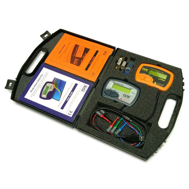
This pack contains the LCR45 Passive Component Impedance Meter, great for advanced hobbyists and professionals. It also contains the very popular DCA Pro (model DCA75), fantastic for component identification, pinout identification, detailed characteristic measurement and curve tracing on a PC. Complete with USB cable and software on a USB flash drive.
DCA75
Building on the continued success of Peak's existing component identification and analysis instruments, the DCA Pro brings an array of exciting new features for the hobbyist and professional alike.
The DCA Pro is an advanced new design that features a graphics display, USB communications, PC Software and an enhanced component identification library.
Automatic component type identification
Automatic pinout identification (connect any way round)
The DCA Pro supports all the components that the popular Peak Atlas DCA55 supports, but adds plenty more. Components supported include:
Transistors (including Darlingtons), Silicon and Germanium types. Measures gain, Vbe and leakage
MOSFETs, enhancement mode and depletion mode types. Measure on-threshold (at 5 mA) and approx transconductance (for span of 3-5 mA)
JFETs, including normally off SiC types. Measures pinch-off voltage (at 1 uA) and approx transconductance (for span of 3-5 mA)
IGBTs (insulated gate bipolar transistors). Measures on-threshold (at 5 mA)
Diodes and Diode networks
LEDs and bicolour LEDs (2 lead and 3 lead types)
Zener Diodes with measurement of zener voltage up to 9 V at 5 mA
Voltage regulators (measures regulation voltage, drop-out voltage, quiescent current)
Triacs and Thyristors that require less than 10 mA of gate current and holding current
Stand-alone or with a PC
The instrument can be used stand-alone or connected to a PC. Either way, the DCA Pro will automatically identify the component type, identify the pinout and also measure a range of component parameters such as transistor gain, leakage, MOSFET and IGBT threshold voltages, pn characteristics and much more.
Curve Tracing
When connected to a PC using the supplied USB cable, a range of low current curve-tracing functions can be performed. Various graph types are available, with more to follow:
Bipolar transistor output characteristics, IC vs VCE
Bipolar transistor gain characteristics, HFE vs VCE
Bipolar transistor gain characteristics, HFE vs IC
MOSFET and IGBT output function, ID vs VDS
MOSFET and IGBT transfer function, ID vs VGS
JFET output function, ID vs VDS
JFET transfer function, ID vs VGS
Voltage regulator, VOUT vs VIN
Voltage regulator, IQ vs VIN.
PN junction I/V curves, forward and reverse options (for Zener diodes)
Curve tracing is performed using test parameters in the range of +/-12 V or +/-12 mA. All curve-tracing data can be instantly pasted into Excel for further graphing and analysis. PC Software is included with the DCA Pro on a Peak USB memory stick. Software designed for Windows 7 and higher (all 32 or 64 bit).
LCR45
A great handheld LCR analyzer that can measure the value of your passive component (inductor, capacitor or resistor) and also measure the detailed impedance in a number of modes. The LCR45 offers enhanced measurement resolution (better than 0.1 uH!) whilst also giving you continuous fluid measurements. Additionally, the test frequencies of DC, 1 kHz, 15 kHz and 200 kHz can be set to automatic or manual modes. Supplied with removable gold plated hook probes, battery and user guide. Compatible with standard 2 mm test connectors. Not designed for in-circuit use.
Automatic or manual component type selection: Inductor, Capacitor or Resistor
Automatic or manual test frequency selection: DC, 1 kHz, 15 kHz and 200 kHz
Inductance from 0.1 uH to 10 H
Capacitance from 0.1 pF to 10,000 uF
Resistance from 0.1 Ohm to 2 MOhm
Inductance measurement also shows DC winding resistance
Display of "Component type and values", "Complex Impedance", "Magnitude/Phase" and "Admittance"
Test frequency displayed for all measurements
Typical accuracy of 1.5% for inductors and capacitors (see spec table for details)
Typical accuracy of 1% for resistors
Test lead complete with gold plated 2 mm plugs and sockets
Supplied with removable gold plated hook probes
Included
LCR45
DCA75
Extra GP23 Battery
Extra AAA cell
Dual Carry Case
,
by Lobna Belarbi
Must-Have Boards, Kits & Tools to Start Your Arduino Journey with Elektor
Whether you're a newcomer eager to explore the world of microcontrollers or an experienced maker seeking to expand your toolkit, Elektor offers a curated selection...