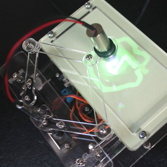
The Elektor Laser Head transforms the Elektor Sand Clock into a clock that writes the time on glow-in-the-dark film instead of sand. In addition to displaying the time, it can also be used to create ephemeral drawings. The 5 mW laser pointer, with a wavelength of 405 nm, produces bright green drawings on the glow-in-the-dark film. For best results, use the kit in a dimly lit room. Warning: Never look directly into the laser beam!
The kit includes all the necessary components, but soldering three wires is required.
Note: This kit is also compatible with the original Arduino-based Sand Clock from 2017. For more details, see Elektor Magazine 1-2/2017 and Elektor Magazine 1-2/2018.
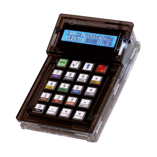
The Elektor MultiCalculator Kit is an Arduino-based multifunction calculator that goes beyond basic calculations. It offers 22 functions including light and temperature measurement, differential temperature analysis, and NEC IR remote control decoding. The Elektor MultiCalculator is a handy tool for use in your projects or for educational purposes.
The kit features a Pro Mini module as the computing unit. The PCB is easy to assemble using through-hole components. The enclosure consists of 11 acrylic panels and mounting materials for easy assembly. Additionally, the device is equipped with a 16x2 alphanumeric LCD, 20 buttons, and temperature sensors.
The Elektor MultiCalculator is programmable with the Arduino IDE through a 6-way PCB header. The available software is bilingual (English and Dutch). The calculator can be programmed with a programming adapter, and it is powered through USB-C.
Modes of Operation
Calculator
4-Ring Resistor Code
5-Ring Resistor Code
Decimal to Hexadecimal and Character (ASCII) conversion
Hexadecimal to Decimal and Character (ASCII) conversion
Decimal to Binary and Character (ASCII) conversion
Binary to Decimal and Hexadecimal conversion
Hz, nF, capacitive reactance (XC) calculation
Hz, µH, inductive reactance (XL) calculation
Resistance calculation of two resistors connected in parallel
Resistance calculation of two resistors connected in series
Calculation of unknown parallel resistor
Temperature measurement
Differential temperature measurement T1&T2 and Delta (δ)
Light measurement
Stopwatch with lap time function
Item counter
NEC IR remote control decoding
AWG conversion (American Wire Gauge)
Rolling Dice
Personalize startup message
Temperature calibration
Specifications
Menu languages: English, Dutch
Dimensions: 92 x 138 x 40 mm
Build time: approx. 5 hours
Included
PCB and though-hole components
Precut acrylic sheets with all mechanical parts
Pro Mini microcontroller module (ATmega328/5 V/16 MHz)
Programming adapter
Waterproof temperature sensors
USB-C cable
Downloads
Software
52 Volumes on USB – Now incl. Volume 2025!
NEW: For articles from the year 2000 onwards, there is now a separate download option for additional materials such as PCB layouts, Gerber files, and software!
This USB stick (64 GB) is loaded with all the Elektor magazine English editions (as PDFs) from 1974 to 2025. Elektor engineers, authors, and editors aim to inspire you to master electronics and computer technology by presenting professionally designed circuits that are easy to build.
We also cover the latest developments in electronics and information technology. With the Elektor Archive on a USB stick, you can browse our previous English editions at your convenience and learn about MCU-based projects, robotics, electronics testing, embedded programming, analog techniques, and much more.
All the Elektor magazine editions are stored as PDFs on a 32-GB USB stick (USB 3.0). The 10,000+ articles have been classified by date of publication (month/year), and a comprehensive index enables you to search the entire USB stick. Subject areas include:
Audio & video
Computers & microcontrollers
Radio, hobby & modelling
Home & garden
Power supplies & batteries
Test & measurement
Software
And everything else that doesn’t fit in one of these categories.
Elektor GPT
Elektor GPT is an AI-powered tool that helps users navigate through the decades-long Elektor archive. Using advanced search algorithms and natural language processing, Elektor GPT quickly finds articles, projects, and other resources from the archive.
Specifications
Storage
64 GB
Interfaces
1x USB-A1x USB-C
System requirements
PC with Adobe Reader 7.0 or higher
Web browser
Raspberry Pi-based Eye Catcher
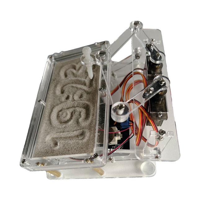
A standard sand clock just shows how time passes. In contrast, this Raspberry Pi Pico-controlled sand clock shows the exact time by “engraving” the four digits for hour and minute into the layer of sand. After an adjustable time the sand is flattened out by two vibration motors and everything begins all over again.
At the heart of the sand clock are two servo motors driving a writing pen through a pantograph mechanism. A third servo motor lifts the pen up and down. The sand container is equipped with two vibration motors to flatten the sand. The electronic part of the sand clock consists of a Raspberry Pi Pico and an RTC/driver board with a real-time clock, plus driver circuits for the servo motors.
A detailed construction manual is available for downloading.
Features
Dimensions: 135 x 110 x 80 mm
Build time: approx. 1.5 to 2 hours
Included
3x Precut acrylic sheets with all mechanical parts
3x Mini servo motors
2x Vibration motors
1x Raspberry Pi Pico
1x RTC/driver board with assembled parts
Nuts, bolts, spacers, and wires for the assembly
Fine-grained white sand
The Elektor Zener Diode Tester is essentially a constant-current source that can be switched in steps from 1 to 50 mA. It can be used to test Z-diodes up to a maximum of 54 V. Thanks to a 60-V step-up converter, the device can be powered by the usual 5 to 12 V.
The principle of this tester is straightforward. A Z-diode or other DUT (device under test, such as an LED) is biased by an adjustable current source. The voltage across the DUT can be measured with a multimeter. The voltage of most (small) Z-diodes is specified at a current of 5 mA. Depending on the application, the voltage at other currents can also be of interest. That is why six current settings are available: 1, 2, 5, 10, 20, and 50 mA. LEDs are often specified at a current of 20 mA.
What can be tested is:
Whether a Z-diode is defective (short circuit or high impedance).
Whether a Z-diode exhibits the correct Z-voltage.
How a Z-voltage changes with different currents.
What exact voltage is present at an integrated voltage reference.
Whether LEDs in a series chain differ in brightness (hence the 20 mA current).
What the current gain is for different base currents in (power) transistors.
The kit contains all parts listed in the bill of materials including PCB and enclosure.
Specifications
Supply voltage
5…12 V/2 A (USB-C)
Supply current (Itest = 50 mA)
1.1 A @ 5 V / 412 mA @ 12 V
Selectable currents
1, 2, 5, 10, 20, and 50 mA
Max. test voltage
>54 V @ Itest ≥1 mA
Max. output voltage
60 V @ Itest = 0 mA
Voltage limit at 5 V
4.5 V @ Itest = 1 mA / 5.18 V @ Itest = 50 mA
Enclosure dimensions
110 x 82 x 44 mm
PCB size
105.4 x 67.3 mm
Connections
4 mm banana sockets for multimeter
2 mm banana sockets for test clips
USB-C socket for power supply
Included
Resistors
R1 = 3.3 kΩ, 600 mW, 1%
R2 = 0.15 Ω, 1 W, 5%, LS 12.7 mm, ø 3.5 mm
R3, R8 = 180 Ω, 600 mW, 1%
R4, R6, R16 = 1 kΩ, 600 mW, 1%
R5, R19 = 47 kΩ, 600 mW, 1%
R7 = 3.9 kΩ, 1 W, 5%, LS 12.7 mm, ø 3.5 mm
R9, R10, R12 = 10 kΩ, 600 mW, 1%
R11, R13 = 100 Ω, 600 mW 1%
R14 = 249 Ω, 600 mW, 1%
R15 = 499 Ω, 600 mW, 1%
R17 = 2.49 kΩ, 250 mW, 1%
R18 = 4.99 kΩ, 250 mW, 1%
Capacitors
C1 = 470 uF / 35 V, 20%, Ir = 1.86 A, ø 12.5 mm, LS 5 mm, ESR = 0.038 Ω (Panasonic EEUTP1V471)
C2 = 1 uF / 100 V, 10%, X7R, LS 5 mm
C3 = 2.2 nF / 50 V, 10%, X7R, LS 5 mm
C4, C7 = 100 nF / 100 V, 10%, X7R, LS 5 mm
C5 = 100 uF / 100 V, 20%, ø 14 mm max., LS 5 mm
C6 = 1 nF / 100 V, 10%, X7R, LS 5 mm
Inductor
L1 = 100 uH, Irms = 2.4 A, Isat = 3.5 A, 0.09 Ω, radial, pitch 2.5/5/10 mm, ø 14 mm max. (Kemet SBC8-101-242)
Semiconductors
D1 = MUR120G, DO-41
D2, D4 = STPS3150RL, DO-201AD
D3 = Z-diode, 18 V, 1.3 W (BZX85C18)
D5 = Z-diode, 5.1 V, 0.5 W (1N5231B)
LED1 = LED in pushbutton S1
LED2 = LED, green, 3 mm
IC1 = MC34063, DIP-8
IC2 = LM4040BIZ-5.0/NOPB, TO-92 (TO-226AA-3)
IC3 = TL051CP, DIP-8
T1 = BC327.25, TO-92
T2 = STP40NF10L, TO-220
T3 = IRF9510PBF, TO-220
T4 = 2N7000, TO-92
Others
K1, K2, S1, S3 = 2-way screw terminal block, LS 3.5 mm, max. 1.5 mm²
connected to K1 = USB-C socket, 30 V/3 A, chassis mounted, wired, 9 x 16 mm
connected to K2 = Banana Connector, 2 mm, Socket, 60 VDC, Panel Mount, red (Multicomp 24.102.1)
connected to K2 = Banana Connector, 2 mm, Socket, 60 VDC, Panel Mount, black (Multicomp 24.102.2)
Test clip, red, 30 VAC/60 VDC (Hirschmann 931467101)
Test clip, black, 30 VAC/60 VDC (Hirschmann 931467100)
S1 = Pushbutton, panel mount, SPST-NO, 30 DC/100 mA, with red LED
S2 = Rotary Switch, 6 position, 2 pole, 30°, 250 V/150 mA
S3 = Toggle switch, panel mount, SPDT, solder lugs, 28 VDC
T2, T3 = Heat sink, 15°C/W, FK 214 SA-CB
Enclosure Hammond 1591XXSSBK, ABS, 110 x 82 x 44 mm
Knob for S2, round shaft 6 mm, ø 21 mm, with indicator line (Multicomp CP-LB21-6-6D)
4 x Self-tapping screw #4-1/4", carbon steel, pan head
Banana plug, red, 2 mm, 60 VDC (Multicomp 25.205.1)
Banana plug, black, 2 mm, 60 VDC (Multicomp 25.205.2)
Banana socket, black 4 mm, panel mount
Banana socket, red 4 mm, panel mount
for LED1, LED2 = Pin header, 1 x 2, vertical, pitch 2.54 mm
for LED1, LED2 = Pin socket, 1 x 2, vertical, pitch 2.54 mm
for T2, T3 = M3 screw, 10 mm, steel, pan head
2 x M3 washer, plain, steel
4 x M3 nut
for IC1, IC3 = DIP-8 socket
Wire, black, 0.25 mm² (24 AWG), stranded 14 x 0.15 mm, 1 m
Wire, red, 0.25 mm² (24 AWG), stranded 14 x 0.15 mm, 1 m
PCB 250772-1 v1.1
Links
Article
Elektor Labs
Over 45 Builds for the Legendary 555 Chip (and the 556, 558)
The 555 timer IC, originally introduced by the Signetics Corporation around 1971, is sure to rank high among the most popular analog integrated circuits ever produced. Originally called the IC Time Machine, this chip has been used in many timer-related projects by countless people over decades.
This book is all about designing projects based on the 555 timer IC. Over 45 fully tested and documented projects are presented. All projects have been fully tested by the author by constructing them individually on a breadboard. You are not expected to have any programming experiences for constructing or using the projects given in the book. However, it’s definitely useful to have some knowledge of basic electronics and the use of a breadboard for constructing and testing electronic circuits.
Some of the projects in the book are:
Alternately Flashing Two LEDs
Changing LED Flashing Rate
Touch Sensor On/Off Switch
Switch On/Off Delay
Light-Dependent Sound
Dark/Light Switch
Tone Burst Generator
Long Duration Timer
Chasing LEDs
LED Roulette Game
Traffic Lights
Continuity Tester
Electronic Lock
Switch Contact Debouncing
Toy Electronic Organ
Multiple Sensor Alarm System
Metronome
Voltage Multipliers
Electronic Dice
7-Segment Display Counter
Motor Control
7-Segment Display Dice
Electronic Siren
Various Other Projects
The projects given in the book can be modified or expanded by you for your very own applications. Electronic engineering students, people engaged in designing small electronic circuits, and electronic hobbyists should find the projects in the book instructive, fun, interesting, and useful.
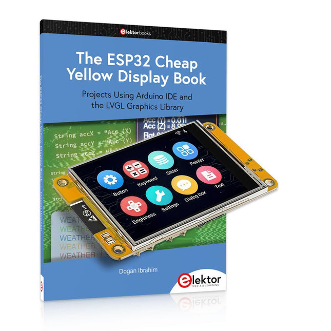
Over 40 Fully Tested ESP32 Projects Using Arduino IDE and the LVGL Graphics Library
This bundle includes the ESP32 Cheap Yellow Display (CYD) – a compact development board combining a standard ESP32 microcontroller with a 320x240 pixel TFT color display. The board also features multiple connectors for GPIO, serial communication (TX/RX), power, and ground. The built-in display is a major advantage, allowing users to create complex, graphics-based projects without the need for external LCDs or displays.
The accompanying book introduces the CYD board's hardware and on-board connectors in detail. It provides a range of beginner to intermediate-level projects developed using the popular Arduino IDE 2.0. Both basic graphics functions and the powerful LVGL graphics library are covered, with practical projects illustrating each approach.
All included projects have been fully tested and are ready to use. The book provides block diagrams, circuit schematics, complete code listings, and step-by-step explanations. With the LVGL library, readers can create modern, full-color graphical interfaces using widgets such as buttons, labels, sliders, calendars, keyboards, charts, tables, menus, animations, and more.
ESP32 Cheap Yellow Display Board
This development board (also known as "Cheap Yellow Display") is powered by the ESP-WROOM-32, a dual-core MCU with integrated Wi-Fi and Bluetooth capabilities. It operates at a main frequency of up to 240 MHz, with 520 KB SRAM, 448 KBROM, and a 4 MB Flash memory. The board features a 2.8-inch display with a resolution of 240x320 and resistive touch.
Furthermore, the board includes a backlight control circuit, touch control circuit, speaker drive circuit, photosensitive circuit, and RGB-LED control circuit. It also provides a TF card slot, serial interface, DHT11 temperature and humidity sensor interface, and additional IO ports.
The module supports development in Arduino IDE, ESP-IDE, MicroPython, and Mixly.
Applications
Image transmission for Smart Home device
Wireless monitoring
Smart agriculture
QR wireless recognition
Wireless positioning system signal
And other IoT applications
Specifications
Microcontroller
ESP-WROOM-32 (Dual-core MCU with integrated Wi-Fi and Bluetooth)
Frequency
Up to 240 MHz (computing power is up to 600 DMIPS)
SRAM
520 KB
ROM
448 KB
Flash
4 MB
Operating voltage
5 V
Power consumption
approx. 115 mA
Display
2.8-inch color TFT screen (240 x 320)
Touch
Resistive Touch
Driver chip
ILI9341
Dimensions
50 x 86 mm
Weight
50 g
Downloads
GitHub
This bundle contains:
The ESP32 Cheap Yellow Display Book (normal price: €35)
ESP32 Cheap Yellow Display Board (normal price: €25)
1x ESP32 Dev Board with 2.8" Display and acrylic Shell
1x Touch pen
1x Connector cable
1x USB cable
This upgraded version 2.0 (available exclusively from Elektor) contains the following improvements:
Enhanced protective earthing (PE) for furnace chassis
Extra thermal insulation layer around furnace to reduce odors
Connection to a computer, allowing curve editing on a PC
Features such as constant temperature control and timing functions
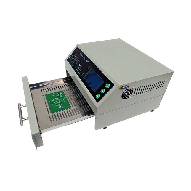
The infrared IC heater T-962 v2.0 is a microprocessor-controlled reflow oven that you can use for effectively soldering various SMD and BGA components. The whole soldering process can be completed automatically and it is very easy to use. This machine uses a powerful infrared emission and circulation of the hot air flow, so the temperature is being kept very accurate and evenly distributed.
A windowed drawer is designed to hold the work-piece, and allows safe soldering techniques and the manipulation of SMDBGA and other small electronic parts mounted on a PCB assembly. The T-962 v2.0 may be used to automatically rework solder to correct bad solder joints, remove/replace bad components and complete small engineering models or prototypes.
Features
Large infrared soldering area
Effective soldering area: 180 x 235 mm; this increases the usage range of this machine drastically and makes it an economical investment.
Choice of different soldering cycles
Parameters of eight soldering cycles are pre defined and the entire soldering process can completed automatically from Preheat, Soak and Reflow through to cool down.
Special heat up and temperature equalization with all designs
Uses up to 800 Watts of energy efficient Infrared heating and air circulation to re-flow solder.
Ergonomic design, practical and easily operated
Good build quality but at the same time light weight and a small footprint allows the T-962 v2.0 to be easily bench positioned transported or stored.
Large number of available functions
The T-962 v2.0 can solder most small parts of PCB boards, for example CHIP, SOP, PLCC, QFP, BGA etc. It is the ideal rework solution from single runs to on-demand small batch production.
Specifications
Soldering area (max)
180 x 235 mm (7.1 x 9.3")
Power (max)
800 W
Temperature range
0-280°C (32-536°F)
Heating method
Infrared
Processing time
1~8 minutes
Power supply
220 V AC/50 Hz
Display
LCD with Backlight
Control mode
8 intelligent temperature curves
Dimensions
310 x 290 x 170 mm (12.2 x 11.4 x 6.7")
Weight
6.2 kg
Included
1x T-962 v2.0 Reflow Soldering Oven (Elektor Version)
2x Fuses
1x Power cord (EU)
Downloads
Manual
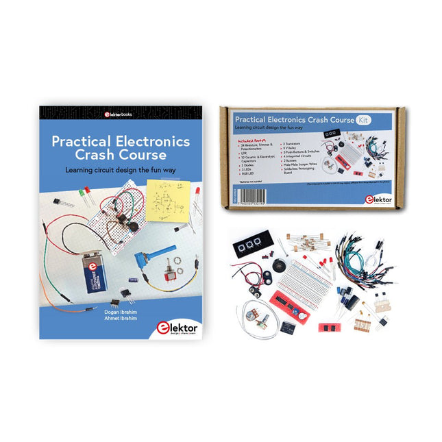
Getting started in electronics is not as difficult as you may think. With this bundle (book + kit of parts), you can explore and learn the most important electrical and electronics engineering concepts in a fun way by doing various experiments. You will learn electronics practically without getting into complex technical jargon and long calculations. As a result, you will be creating your own projects soon.
This kit contains the components required to build most of the detailed examples of the book on a breadboard and try them out for real.
The kit can, of course, also be used without the book for building other circuits and doing your own experiments.
Kit contents
1x 39 Ω, 1 W resistor
1x 47 Ω resistor
1x 180 Ω resistor
1x 330 Ω resistor
3x 1 kΩ resistor
1x 2.2 kΩ resistor
1x 3.9 kΩ resistor
1x 6.8 kΩ resistor
1x 10 kΩ resistor
1x 15 kΩ resistor
1x 22 kΩ resistor
1x 33 kΩ resistor
1x 47 kΩ resistor
1x 56 kΩ resistor
1x 82 kΩ resistor
1x 120 kΩ resistor
1x 680 kΩ resistor
2x 100 kΩ resistor
1x 10 kΩ trimmer
1x 10 kΩ linear potentiometer
1x 100 kΩ linear potentiometer
1x LDR
1x 1 nF ceramic capacitor
2x 10 nF ceramic capacitor
1x 100 nF ceramic capacitor
1x 1 µF, 25 V aluminium electrolytic capacitor
2x 10 µF, 25 V aluminium electrolytic capacitor
1x 100 µF, 25 V aluminium electrolytic capacitor
1x 470 µF, 25 V aluminium electrolytic capacitor
1x 1000 µF, 25 V aluminium electrolytic capacitor
1x RGB LED, Common-Cathode (CC)
1x 1N4148 small signal diode
1x 1N4733A 5.1 V, 1 W Zener diode
3x LED, red
2x BC337 NPN transistor
1x IRFZ44N N-channel MOSFET
2x NE555 timer
1x LM393 comparator
1x 74HCT08 quad AND gate
3x Tactile switch
2x SPDT switch
1x Relay, SPDT, 9 VDC
1x Active buzzer
1x Passive buzzer
50 cm Solid wire, 16 AWG, unjacketed
2x PP3 9 V battery clip
1x Breadboard
20x Jumper wire
This bundle contains:
Practical Electronics Crash Course Kit (valued at: €45)
Book: Practical Electronics Crash Course (normal price: €45)
Vision and Mission Elektor believes that innovations in electronics will lead to a better world. Elektor is a multi-faceted platform in the applied electronics industry that unites hundreds of thousands engineers, programmers and developers in a worldwide community of knowledge and expertise. Since its founding in 1960, Elektor has been dedicated...
Read more
,
by Lobna Belarbi
Kickstart Your Electronics Journey with Elektor’s Learning Collection
Whether you're new to electronics or aiming to level up your embedded skills, Elektor’s Learning Collection delivers expert-curated kits, courses, and hands-on bundles. The first...