Search results for "simple OR servo OR tester OR 120474 OR 1"
-
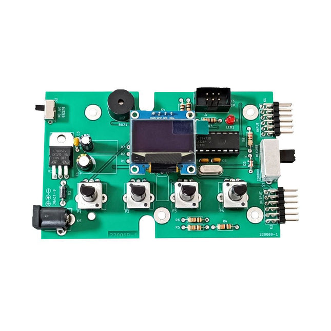
Elektor Labs Elektor Super Servo Tester Kit
The Elektor Super Servo Tester can control servos and measure servo signals. It can test up to four servo channels at the same time. The Super Servo Tester comes as a kit. All the parts required to assemble the Super Servo Tester are included in the kit. Assembling the kit requires basic soldering skills. The microcontroller is already programmed. The Super Servo Tester features two operating modes: Control/Manual and Measure/Inputs. In Control/Manual mode the Super Servo Tester generates control signals on its outputs for up to four servos or for the flight controller or ESC. The signals are controlled by the four potentiometers. In Measure/Inputs the Super Servo Tester measures the servo signals connected to its inputs. These signals may come from for instance an ESC, a flight controller, or the receiver or another device. The signals are also routed to the outputs to control the servos or the flight controller or ESC. The results are shown on the display. Specifications Operating modes Control/Manual & Measure/Inputs Channels 3 Servo signal inputs 4 Servo signal outputs 4 Alarm Buzzer & LED Display 0.96' OLED (128 x 32 pixels) Input voltage on K5 7-12 VDC Input voltage on K1 5-7.5 VDC Input current 30 mA (9 VDC on K5, nothing connected to K1 and K2) Dimensions 113 x 66 x 25 mm Weight 60 g Included Resistors (0.25 W) R1, R3 1 kΩ, 5% R2, R4, R5, R6, R7, R9, R10 10 kΩ, 5% R8 22 Ω, 5% P1, P2, P3, P4 10 kΩ, lin/B, vertical potentiometer Capacitors C1 100 µF 16 V C2 10 µF 25 V C3, C4, C7 100 nF C5, C6 22 pF Semiconductors D1 1N5817 D2 LM385Z-2.5 D3 BZX79-C5V1 IC1 7805 IC2 ATmega328P-PU, programmed LED1 LED, 3 mm, red T1 2N7000 Miscellaneous BUZ1 Piezo buzzer with oscillator K1, K2 2-row, 12-way pinheader, 90° K5 Barrel jack K4 1-row, 4-way pin socket K3 2-row, 6-way boxed pinheader S1 Slide switch DPDT S2 Slide switch SPDT X1 Crystal, 16 MHz 28-way DIP socket for IC2 Elektor PCB OLED display, 0.96', 128 x 32 pixels, 4-pin I²C interface Links Elektor Magazine Elektor Labs
€ 59,95€ 49,95
Best Price
-
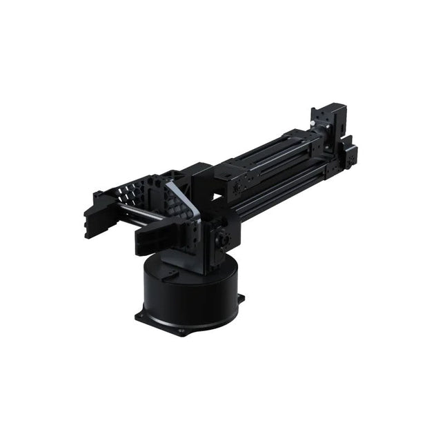
Unitree Unitree Go2 D1 Servo Robotic Arm
The Unitree Go2 D1 Servo Robotic Arm is a high-performance 6-DOF robotic arm, purpose-built for seamless integration with the Unitree Go2 Quadruped Robot. Designed for flexibility and precision, it’s an ideal tool for education, research, automation, and advanced robotics development. Featuring six fully articulated joints and an integrated gripper, the D1 offers true six-axis motion and exceptional freedom of movement. With support for position, velocity, and force control, it enables precise operation across a wide range of tasks – from real-world deployment to experimental learning environments. Constructed from lightweight aluminum alloy, the arm weighs just 2.37 kg while maintaining a reach of 670 mm. This balance of strength and agility makes it well-suited for mobile applications, without compromising stability or range. Thanks to its dual-level interface architecture, the D1 supports both low-level motor commands and high-level behavior programming – giving developers, educators, and researchers full control, whether they’re fine-tuning motion sequences or building complex robotic workflows. Compatible with external components like cameras or mobile robot chassis, the Unitree D1 opens the door to a variety of expanded use cases. Whether it's autonomous object manipulation, AI training, or hands-on robotics education, the D1 transforms any environment into a dynamic and interactive innovation platform. Specifications DoF 6 Axis + 1 Gripper Payload 500 g Arm Reach 550 mm (Gripper not included)670 mm (Gripper included) Interfaces DC5.5-2.1 (Power Supply)RJ45 (Communication)USB-C (Serial Port Debugging) Motor Type Bus Servo Power 60 W Weight 2.37 kg Joint Rotation Range J1: ±135°J2: ±90°J3: ±90°J4: ±135°J5: ±90°J6: ±135°
€ 4.599,00
Best Price
-

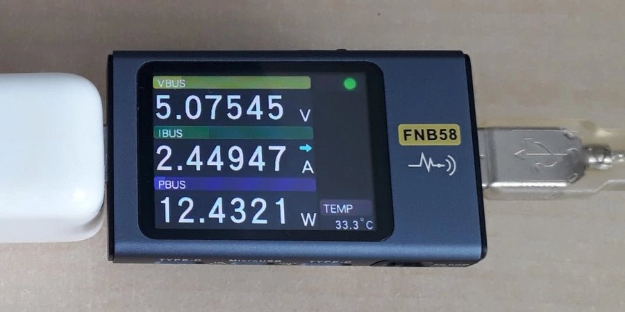
FNIRSI FNIRSI FNB58 USB Tester (with Bluetooth)
The FNIRSI FNB58 USB tester (with Bluetooth) is a comprehensive and very accurate USB voltage and current meter. It features a 2.0-inch full-color HD TFT display, built-in USB-A, micro USB and USB-C interface. With this device you can measure the power supply or power consumption of products or the charging power of cell phones and power supplies. You can also determine the fast charging protocol of chargers. Features USB-A and USB-C interface 2.0" HD display Data at a glance Wide compatibility Ultra-precise data detection Play with fast charging technology Automatic protocol detection (PD2.0, 3.0, 3.1, PPS, QC2.0, 3.0, FCP, SCP, AFC, PE, DASH VOOC, SuperVOOC and more) Simple user interface, easy to operate 4 function curve displays (real-time voltage and current curve, offline curve recording, D+/D- voltage curve, high-speed power supply ripple measurement) Cable detection 10 groups of energy recording battery capacity calculation PC connectivity for data logging and firmware updates Bluetooth app for Android devices Specifications Voltage range 4-28 V Current range 0-7 A Power range 0-120 W Load equivalent internal resistance 0-9999.9 Ω D+/D- voltage 0-3.3 V Capacity 0-9999.99 Ah Power consumption 0-9999.99 Wh Cable resistance 0-9999.9 Ω Interfaces micro USB, USB-A, USB-C Dimensions 42 x 13 x 82 mm Downloads Manual Firmware V0.68
€ 49,95
-
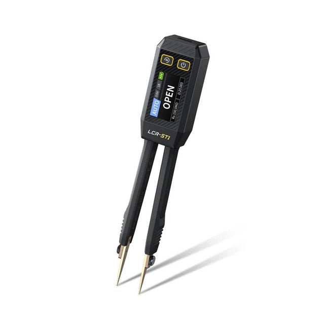
FNIRSI FNIRSI LCR-ST1 Smart SMD Tweezers (LCR/ESR Tester)
The FNIRSI LCR-ST1 is a compact, multifunctional, and smart LCR tester that supports automatic measurements of resistance, capacitance, inductance, diode testing, and continuity. Its 1.14-inch color display combined with a convenient magnetic adsorption function enhances ease of use, while the built-in 250 mAh lithium battery ensures long-lasting performance. The device supports three frequency ranges (100 Hz, 1 kHz and 10 kHz) and offers 0.3 V and 0.6 V RMS test levels for versatile testing applications. The unique tweezer-shaped design of the LCR-ST1 is ideal for delicate tasks in confined spaces and enables fast and accurate testing of electronic components. Its light weight and portable design make it an invaluable tool for both field and laboratory use. Whether you are an experienced engineer or just starting out in electronics, the LCR-ST1 delivers reliable and accurate measurement results, allowing you to complete your tasks with greater efficiency and precision. Features Offers 3 test frequencies (100 Hz, 1 kHz, 10 kHz) and 2 test voltage levels. Features automatic component identification for faster and more reliable measurements. High-resolution 1.14-inch color display for clear readouts. Supports automatic data recording and storage. The tweezer tips are made from gold-plated brass for enhanced durability and conductivity. Specifications Resistance Range 10 mΩ – 10 MΩ Capacitance Range 1 pF – 22 mF Inductance Range 1 μh – 10 H Diode On voltage 0.7 V Frequency Test 100 Hz, 1k Hz, 10 KHz Level Test 0.3 V, 0.6 V RMS Parameter Display ESR, D value, Q value, Z value, X value Display 1.14" HD color screen Charging Interface USB-C, 5 V/1 A Power Supply Built-in 250 mAh lithium battery Auto Recognition Measurement Yes Replaceable Tweezer Head Yes Auto Shutdown Yes Data Hold Yes History Record Connect to PC to view and export Dimensions 28 x 19 x 150 mm Weight 41 g Included 1x LCR-ST1 SMD Tweezers 2x Hook Tips 1x Magnetic Patch 1x USB cable 1x Tool bag 1x Manual Downloads Manual Firmware V1.6
€ 34,95
-
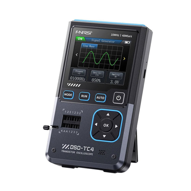
FNIRSI FNIRSI DSO-TC4 (3-in-1) Oscilloscope (10 MHz) + Transistor Tester + Signal Generator
The FNIRDSI DSO-TC4 is a multifunctional transistor oscilloscope that is both comprehensive and practical. It is designed for use in maintenance and R&D applications, integrating an oscilloscope, transistor tester, and signal generator into a single device. Features Equipped with a 2.8-inch TFT color screen for a clear and intuitive display Built-in high-capacity rechargeable lithium battery (1500 mAh) with a standby time of up to 4 hours Compact and lightweight, ideal for mobile use Specifications Oscilloscope Analog Bandwidth 10 MHz Real-Time Sampling Rate 48 MSa/s Input Impedance 1 MΩ Coupling Mode AC/DC Test Voltage Range 1:1 Probe: 80 Vpp (+40 V) 10:1 Probe: 800 Vpp (+400 V) Vertical Sensitivity 10 mV/div~10 V/div (X1 range) Vertical Displacement Adjustable with indication Time Base Range 50ns~20s Trigger Mode Auto/Normal/Single Trigger Type Rising edge, Falling edge Trigger Level Adjustable with indication Waveform Freeze Yes (HOLD function) Automatic Measurement Max, Min, Avg, RMS, Vpp, Frequency, Cycle, Duty Cycle Component Tester Transistor Amplification factor "hfe"; Base-Emitter voltage "Ube", Ic/Ie, Collector-Emitter reverse leakage current "Iceo", Ices, Forward voltage drop of protection diode "Uf" Diode Forward voltage drop <5 V (Forward voltage drop, Junction capacitance, Reverse leakage current) Zener Diode 0.01~32 V Reverse Breakdown Voltage (K-A-A Test Area) Field-Effect Transistor (FET) JFET: Gate capacitance "Cg", Drain current Id under "Vgs", Forward voltage drop of protection diode "Uf" IGBT: Drain current Id under Vgs, Forward voltage drop of protection diode Uf MIOSTET: Threshold voltage "Vt", Gate capacitance "Cg", Drain-Source resistance "Rds", Forward voltage drop of protection diode "Uf" Unidirectional SCR Trigger voltage <5V, Gate level (Gate voltage) Bidirectional SCR Trigger current <6mA (Gate voltage) Capacitor 25pF~100mF, Capacitance value, Loss factor "Vloss" Resistor 0.01Ω~50MΩ Inductor 10μH~1000μH, DC resistance DS18B20 Temperature sensor, Pins: GND, DQ, VDD DHT11 Temperature and humidity sensor, Pins: VDD, DATA, GND Signal Generator Output Waveform Supports 13 waveform outputs Waveform Frequency 0-50 KHz Square Wave Duty Cycle 0-100% Waveform Amplitude 0.1-3.0 V General Display 2.8-inch TFT color screen Backlight Brightness adjustable Power Supply USB-C (5 V/1 A) Battery 3.7 V/1500 mAh Languages English, German, Spanish, Portuguese, Russian, Chinese, Japanese, Korean Dimensions 90 x 142 x 27.5 mm Weight 186 g Included 1x FNIRSI DSO-TC4 (3-in-1) Oscilloscope (10 MHz) 1x P6100 Oscilloscope probes (10X) 1x Alligator clip probe 3x Test hooks 1x Adapter 1x USB-C charging cable 1x Manual Downloads Manual Firmware V0.0.7 (+V1.0.9)
€ 89,95€ 74,95
Best Price
-
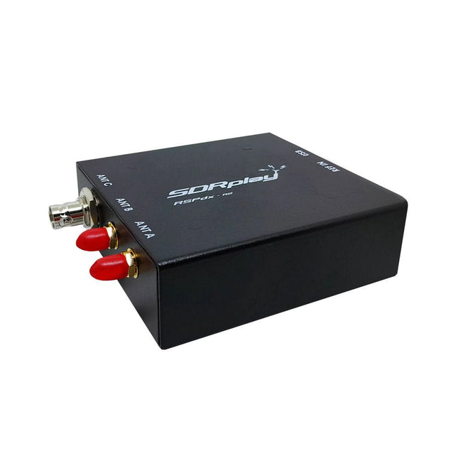
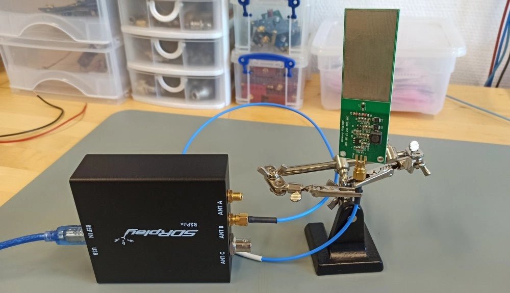
SDRplay SDRplay RSPdx-R2 Single-Tuner 14-bit SDR Receiver (1 kHz to 2 GHz)
The SDRplay RSPdx-R2 is a wideband full featured single-tuner 14-bit SDR receiver which covers the entire RF spectrum from 1 kHz to 2 GHz giving up to 10 MHz of spectrum visibility. It contains three antenna ports, two of which use SMA connectors and operate across the full 1 kHz to 2 GHz range and the third uses a BNC connector which operates up to 200 MHz. The RSPdx-R2 is an enhanced version of the RSPdx with further design improvements for use at frequencies below 2 MHz. Housed in a strong steel case, in addition to the functionality of the RSP1B, the RSPdx-R2 provides three software selectable antenna inputs and an external clock input. It offers excellent performance through HF and VHF frequencies all the way up to 2 GHz. The RSPdx-R2 also supports an "HDR mode" optimised for the demanding radio reception conditions below 2 MHz. The RSPdx-R2, when used in conjunction with SDRplay’s own software, introduces a special HDR (High Dynamic Range) mode for reception within selected bands below 2 MHz. HDR mode delivers improved intermodulation performance and fewer spurious responses for those challenging bands. Features Covers all frequencies from 1 kHz through VLF, LF, MW, HF, VHF, UHF and L-band to 2 GHz, with no gaps Receive, monitor and record up to 10 MHz of spectrum at a time Significantly improved noise performance below 1 MHz (i.e. for some MF, LF and below) Improved dynamic range below 2 MHz both in tuner mode and HDR mode HDR mode below 2 MHz giving overall dynamic range and selectivity advantages Software selectable choice of 3 antenna ports External clock input for synchronisation purposes, or connection to GPS reference clock for extra frequency accuracy Excellent dynamic range for challenging reception conditions Free use of Windows-based SDRuno software (check website for versions supported) Free use of SDRconnect SDR and server software for Windows, MacOS and Linux (Check website for versions supported) Multiplatform driver and API support including Windows, Linux, Mac and Raspberry Pi 4/5 Strong and growing software support network Calibrated S meter/RF power and SNR measurement with SDRuno (including datalogging to .CSV file capability) Documented API provided to allow demodulator or application development on multiple platforms Applications (Amateur) Shortwave radio listening Broadcast DXing (AM/FM/TV) Panadaptor Aircraft (ADS-B and ATC) Slow Scan TV Multi-amateur band monitoring WSPR & digital modes Weather fax (HF and satellite) Satellite monitoring Geostationary environmental satellites Trunked radio Utility and emergency service monitoring Fast and effective antenna comparison Applications (Industrial) Spectrum Analyser Surveillance Wireless microphone monitoring RF surveying IoT receiver chain Signal logging RFI/EMC detection Broadcast integrity monitoring Spectrum monitoring Power measurement Applications (Educational/Scientific) Teaching Receiver design Radio astronomy Passive radar Ionosonde Spectrum analyser Receiver for IoT sensor projects Antenna research Specifications Frequency Range 1 kHz – 2 GHz Antenna Connector SMA Antenna Impedance 50 Ohms Current Consumption (Typical) 190 mA @ >60 MHz (excl. Bias-T)120 mA @ <60 MHz (excl. Bias-T) USB Connector USB-B Maximum Input Power +0 dBm Continuous+10 dBm Short Duration ADC Sample Rates 2-10.66 MSPS ADC Number of Bits 14 bit 2-6.048 MSPS12 bit 6.048-8.064 MSPS10 bit 8.064-9.216 MSPS8 bit >9.216 MSPS Bias-T 4.7 V100 mA guaranteed Reference 0.5ppm 24 MHz TCXOFrequency error trimmable to 0.01ppm in field Operating Temperature −10˚C to +60˚C Dimensions 113 x 94 x 35 mm Weight 315 g Downloads Datasheet Software RSPdx-R2 vs RSPduo RSPdx-R2 RSPduo Continuous coverage from 1 kHz to 2 GHz ✓ ✓ Up to 10 MHz visible bandwidth ✓ ✓ 14-bit ADC silicon technology plus multiple high-performance input filters ✓ ✓ Software selectable AM/FM & DAB broadcast band notch filters ✓ ✓ 4.7 V Bias-T for powering external remote antenna amplifier ✓ ✓ Powers over the USB cable with a simple type B socket ✓ ✓ 50Ω SMA antenna input(s) for 1 kHz to 2 GHz operation (software selectable) 2 2 Additional software selectable Hi-Z input for up to 30 Mhz operation ✓ Additional software selectable 50Ω BNC input for up to 200 MHz operation ✓ Additional LF/VLF filter for below 500 kHz ✓ 24 MHz reference clock input (+ output on RSPduo) ✓ ✓ Dual tuners enabling reception on 2 totally independent 2 MHz ranges ✓ Dual tuners enabling diversity reception using SDRuno ✓ Rugged black painted steel case ✓ ✓ Overall performance below 2 MHz for MW and LF ++ + Multiple simultaneous applications + ++ Performance in challenging fading conditions (*using diversity tuning) + *++
€ 263,00
-

Arduino Official Arduino USB-C Cable (2-in-1)
Now you can connect your Arduino boards with the official Arduino USB cable. Through a USB-C to USB-C with a USB-A adapter connection, this data USB cable can easily connect your Arduino boards with your chosen programming device. The Arduino USB cable has a nylon braided jacket in the typical Arduino colors white and teal. The connectors have an aluminum shell that protects your cable from harm at the same time as looking cool. Length: 100 cm Aluminium shell with logo Nylon braided jacket white and teal
€ 12,95
Members: € 11,66
-

OWON OWON HDS120 (2-in-1) True RMS Multimeter & Oscilloscope
The OWON HDS120 is a precise 4½-digit True RMS multimeter (20,000 counts), ideal for professionals, makers, and students. It offers intelligent probe detection, automatic waveform measurements (Vmax, Vmin, Vp-p, Vavg, Vrms, and frequency) and a fully featured handheld oscilloscope (1 MHz). Features Multifunctional Measuring Instrument: 4½-digit Multimeter + Oscilloscope Automatic Waveform Measurements: Including Vmax, Vmin, Vp-p, Vavg, Vrms, and frequency. User-Friendly Design: Clearly labeled keys for easy operation and increased device lifespan. Intelligent Probe Detection: Automatically switches measurement functions based on the probe insertion, effectively preventing instrument damage caused by incorrect operation. Efficient Energy Management: Powered by 18650 lithium batteries, ensuring longer operating time and enhanced reliability for extended measurement tasks. Safe High-Voltage Measurement: Complies with CAT Ⅲ 1000 V standards, allowing safe and direct measurement of high-voltage waveforms up to 1000 V, broadening application possibilities. High-Definition Display: Features a 2.8-inch IPS screen with a wide viewing angle, ensuring clear readability from any perspective. Adaptive Environmental Display: High-brightness and high-contrast dual-theme display modes provide optimal visibility under bright and low-light conditions, improving overall usability. Multimeter Specifications Measurement Range Accuracy DC Voltage (V) 20.000mV / 200.00mV / 2.0000V / 20.000V / 200.00V / 1000.0V ±(0.1%+5dig) AC Voltage (V) 20.000mV / 200.00mV / 6.0000V / 60.000V / 600.00V / 750.00V ±(0.6%+10dig) DC Current (A) 200.00uA / 2000.0uA / 20.000mA / 200.00mA / 2.0000A / 10.000A ±(0.5%+10dig) AC Current (A) 200.00uA / 2000.0uA / 20.000mA / 200.00mA / 2.0000A / 10.000A ±(0.8%+10dig) Resistance (Ω) 200.00Ω / 2.0000kΩ / 20.000kΩ / 200.00KΩ / 2.0000MΩ / 20.000MΩ / 100.00MΩ ±(0.3%+5dig) Capacitance (F) 2.000nF / 20.00nF / 200.0nF / 2.000μF / 20.00μF / 200.0μF / 2.000mF / 20.00mF ±(3.0%+10dig) Frequency (Hz) 200.00Hz / 2.0000kHz / 20.000kHz / 200.00kHz / 2.0000MHz / 20.000MHz ±(0.1%+5dig) Duty Cycle 0.1%~99.9% (typical value: Vrms=1V, f=100Hz) ±(1.2%+3dig) 0.1%~99.9% (≥1kHz) ±(2.5%+10dig) Diode 3.0000V ±(1.0%+10dig) On-Off 1000.0Ω Display 20000 Oscilloscope Specifications Analog bandwidth 1 MHz (only ACV scale) Channel 1 Time base range 2.5us~10s/grid Voltage vertical sensitivity range 30 mV~500 V/grid Vertical amplitude accuracy ±(5% + 0.2div) Maximum voltage limit 1000 V DC+AC Peak value Trigger mode Auto/Normal/Single Auto set Time base/Vertical amplitude/Trigger value Maximum sample 5.0 MSa/s Input impedance ≈10 MΩ Time base accuracy ±(0.01% + 0.1div) Current vertical sensitivity range 100 μA~5 A/grid Measurement function Vmax, Vmin, Vp-p, Vavg, Vrms, Hz Maximum current limit 15 A DC+AC Peak value Trigger edge Rise edge/Fall edge General Specifications Display 2.8" LCD (320 x 240) Low battery indication Yes Backlight Yes Sleep Mode Yes Input Protection Yes Relative Measurement Yes Input Impedance ≥10 MΩ Battery 18650 Lithium Safety Compliance CAT III 1000V Dimensions 93 x 41.5 x 188 mm Weight 0.35 kg Included 1x OWON HDS120 Multimeter & Oscilloscope 2x Multimeter leads 1x USB cable 1x Storage bag 1x Manual Downloads Datasheet Manual
€ 59,00


-
, by Jean-François Simon Fnirsi FNB58 USB Tester (Review)
The Fnirsi FNB58 is a versatile USB tester capable of performing a wide array of voltage, current, and energy measurements, as well as supporting numerous...
-
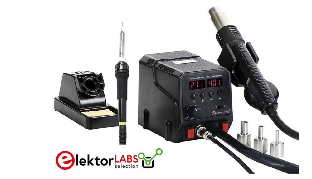
, by Mathias Claussen Review: 2-in-1 SMD Hot Air Rework Station (ZD-8922)
The ZD-8922 2-in-1 SMD Hot Air Rework Station is a tool that makes soldering less of a hassle – especially if you are dealing with...
-
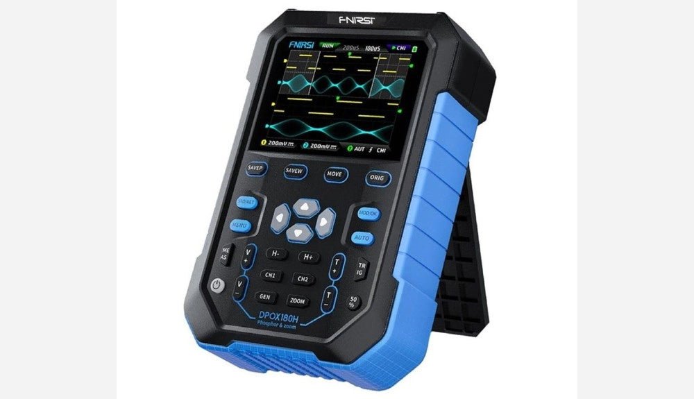
, by Clemens Valens FNIRSI DPOX180H 2-in-1 Digital Phosphor Oscilloscope (Review)
Oscilloscopes sure have made a lot of progress over the past two decades. Twenty years ago, I still used my single-beam analog 20 MHz CRT oscilloscope...
-
, by Sebastian Westerhold The SDRplay RSPdx SDR Receiver Features Frequency Range of 1 kHz up to 2 GHz (Review)
The SDRplay RSPdx is a 14-bit single-tuner receiver with continuous coverage from 1 kHz up to 2GHz. Three input connectors, an ample array of software...


