Book: Mastering the Arduino Uno R4
Based on the low-cost 8-bit ATmega328P processor, the Arduino Uno R3 board is likely to score as the most popular Arduino family member, and this workhorse has been with us for many years. Eleven years later, the long-overdue successor, the Arduino Uno R4, was released. It is built around a 48 MHz, 32-bit Arm Cortex-M4 microcontroller and provides significantly expanded SRAM and Flash memory. Additionally, a higher-precision ADC and a new DAC are added to the design. The Uno R4 board also supports the CAN Bus with an interface.
Two versions of the board are available: Uno R4 Minima, and Uno R4 WiFi. This book is about using these new boards to develop many different and interesting projects with just a handful of parts and external modules. All projects described in the book have been fully tested on the Uno R4 Minima or the Uno R4 WiFi board, as appropriate.
The project topics include the reading, control, and driving of many components and modules in the kit as well as on the relevant Uno R4 board, including
LEDs
7-segment displays (using timer interrupts)
LCDs
Sensors
RFID Reader
4x4 Keypad
Real-time clock (RTC)
Joystick
8×8 LED matrix
Motors
DAC (Digital-to-analog converter)
LED matrix
WiFi connectivity
Serial UART
CAN bus
Infrared controller and receiver
Simulators
… all in creative and educational ways with the project operation and associated software explained in great detail.
Arduino Uno R4 WiFi
The Arduino Uno R4 is powered by the Renesas RA4M1 32-bit ARM Cortex-M4 processor, providing a significant boost in processing power, memory, and functionality. The WiFi version comes with an ESP32-S3 WiFi module in addition to the RA4M1, expanding creative opportunities for makers and engineers.
The Arduino Uno R4 runs at 48 MHz, which provides a 3x increase over the popular Uno R3. Additionally, SRAM has been upgraded from 2 kB to 32 kB, and flash memory from 32 kB to 256 kB to support more complex projects. Responding to community feedback, the USB port is now USB-C, and the maximum power supply voltage has been raised to 24 V with an enhanced thermal design. The board includes a CAN bus and an SPI port, enabling users to reduce wiring and perform parallel tasks by connecting multiple shields. A 12-bit analog DAC is also provided on the board.
Specifications
Microcontroller
Renesas RA4M1 (ARM Cortex-M4)
USB
USB-C
Programming Port
Pins
Digital I/O Pins
14
Pins
Analog input pins
6
DAC
1
RTC
1
PWM pins
6
Communication
UART
1x
I²C
1x
SPI
1x
Qwiic I²C connector
1x
CAN
1x CAN Bus
Power
Circuit operating voltage
5 V
Input voltage (VIN)
6-24 V
DC Current per I/O Pin
8 mA
Clock speed
Main core
48 MHz
Memory
RA4M1
256 kB Flash, 32 kB RAM
LED Matrix
12 x 8 (96 red LEDs)
Dimensions
68.9 x 53.4 mm
Downloads
Datasheet
Schematics
This bundle contains:
Book: Mastering the Arduino Uno R4 (normal price: €45)
Arduino Uno R4 WiFi (normal price: €30)
DEAL: Order the HackRF Pro now and get the new e-book "SDR with HackRF One & HackRF Pro" worth €20 for FREE!
HackRF Pro is latest Software Defined Radio (SDR) from Great Scott Gadgets and the powerful successor to the legendary HackRF One. With a frequency range from 100 kHz to 6 GHz, it covers an enormous spectrum for transmitting and receiving radio signals.
Designed as an open-source hardware platform, the HackRF Pro is the ideal tool for analyzing and developing modern wireless technologies. It can be used flexibly as a USB peripheral or programmed for standalone operation.
Specifications
Frequency: 100 kHz to 6 GHz
Adjustable from 0 Hz to 7.1 GHz
Half-duplex transceiver
Up to 20 million samples per second
8-bit quadrature samples (8-bit I and 8-bit Q)
Compatible with GNU Radio, SDR#, and more
Software-configurable RX and TX gain and baseband filter
Software-controlled RF port power (50 mA at 3.3 V)
SMA RF connector
SMA clock input and output for synchronization and triggering
Convenient buttons for programming
Internal pin headers for expansion
High-Speed USB 2.0 with USB-C connector
USB-powered
Open source hardware
Compared to its predecessor, HackRF Pro offers a variety of new features, including:
Wider operating frequency range
Improved RF performance with flatter frequency response
USB-C connector
Built-in TCXO crystal oscillator for superior timing stability
Logic upgrade from a CPLD to a power-efficient FPGA
Elimination of the DC spike
Extended-precision mode with 16-bit samples for low sample rates (typical ENOB: 9-11)
Half-precision mode with 4-bit samples at up to 40 Msps
More RAM and flash memory for custom firmware
Installed shielding around the radio section
Trigger input and output accessible through clock connectors
Cutout in the PCB provides space for future add-ons
Improved power management
Enhanced RF port protection
Facility to hardware-disable transmit mode
Full Compatibility: Thanks to its proven architecture, existing software for the HackRF One can also be used directly with the HackRF Pro. The HackRF Pro offers seamless backward compatibility while significantly increasing performance.
Note: An antenna is not included. We recommend the ANT500 for the best experience.
Included
HackRF Pro SDR with plastic enclosure
NEW e-book: SDR with HackRF One & HackRF Pro (normal price: €20)
Downloads
Documentation
GitHub
Programming with GNU Radio
HackRF is an open-source hardware platform developed by Great Scott Gadgets and serves as a versatile front end for software-defined radio (SDR). With HackRF One and its successor, HackRF Pro, users can develop their own SDR applications, build powerful receivers and transmitters, and tackle demanding RF measurement tasks.
This book provides a practical introduction to the world of SDR. Step by step, the author shows how powerful SDR projects can be implemented with HackRF – from the fundamentals of RF technology to advanced applications using GNU Radio.
In addition to working with SDR Sharp (SDR#), RadioConda, and GNU Radio, the book also covers the fundamentals of modern digital signal processing. Numerous experiments and easy-to-follow practical examples guide readers through topics such as AM, FM, and SSB reception, digital filters, shortwave radio, amateur radio, signal generators, and custom RF projects up to 6 GHz.
Whether you are a maker, radio amateur, electronics enthusiast, or SDR beginner, this book provides solid knowledge, practical applications, and the motivation to creatively explore the possibilities of modern SDR technology.
Programming with GNU Radio
HackRF is an open-source hardware platform developed by Great Scott Gadgets and serves as a versatile front end for software-defined radio (SDR). With HackRF One and its successor, HackRF Pro, users can develop their own SDR applications, build powerful receivers and transmitters, and tackle demanding RF measurement tasks.
This book provides a practical introduction to the world of SDR. Step by step, the author shows how powerful SDR projects can be implemented with HackRF – from the fundamentals of RF technology to advanced applications using GNU Radio.
In addition to working with SDR Sharp (SDR#), RadioConda, and GNU Radio, the book also covers the fundamentals of modern digital signal processing. Numerous experiments and easy-to-follow practical examples guide readers through topics such as AM, FM, and SSB reception, digital filters, shortwave radio, amateur radio, signal generators, and custom RF projects up to 6 GHz.
Whether you are a maker, radio amateur, electronics enthusiast, or SDR beginner, this book provides solid knowledge, practical applications, and the motivation to creatively explore the possibilities of modern SDR technology.
Practical Guide to Modular RF Design
Build Your Own Software-Defined Radio combines RF circuitry with hardware programming and PC-based signal processing. The e-book presents a modular approach to building a complete SDR system using RF Bricks – from the mechanical framework and RF modules to measurement tools, PC software, and FPGA implementations. Practical explanations guide readers through real signal paths, construction steps, and measurement routines, linking hardware and software into a flexible SDR platform.
Key topics include:
Mechanical setup: RF Brick template, chassis, and 19-inch module carrier
Bridges: USB isolator, I²C level shifter, I²C power switch, and practical examples
Signal-chain design with RF Bricks: antennas, band filters, NanoVNA work, preamplifiers, PLLs, demodulators, direct-conversion chains, multiband options, and narrowband bricks
RF measurement Bricks: single- and dual-tone sources, NPR methods, noise generators, notch filters, broadband amplifiers, and impedance bridges
Useful accessories: ATU-100 tuner, X-Phase QRM eliminator, and firmware notes
PC host software: SoapyAudio adjustments, GQRX, SDR++, and added functionality
GnuRadio elements: control blocks, SSB demodulation, GUI components, messaging, and filter handling
FPGA-based SDR: VHDL, toolchains, ADC/DAC blocks, oversampling, and a complete SSB/CW signal chain
With its modular structure and detailed working examples, this e-book offers a practical path to building and extending modern SDR systems.
Downloads
Software
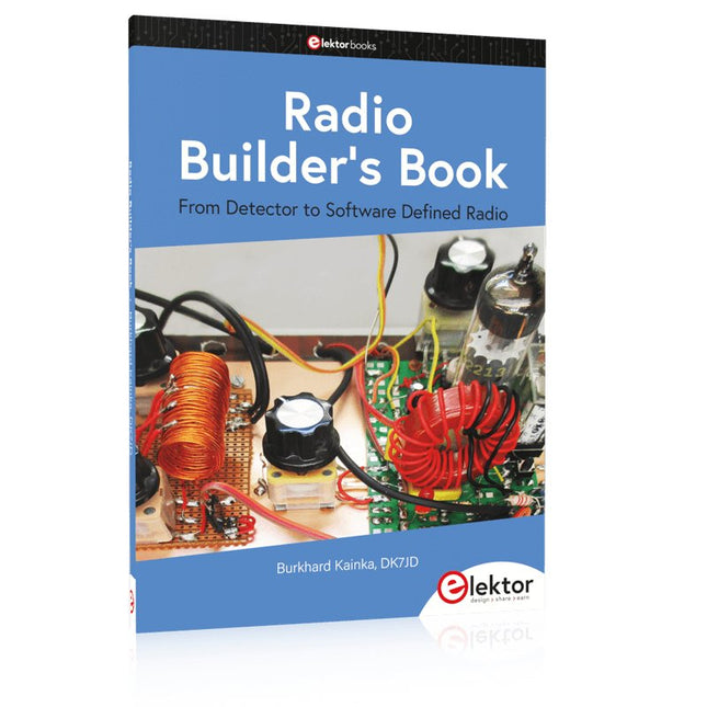
From Detector to Software Defined Radio
Radio frequency (RF) technology is one of the areas which still allows putting your own ideas into practice. Countless circuit variants with special objectives allow space for meaningful experiments and projects. Many things simply aren’t available off the shelf. Crystal detector radios without their own power source, simple tube receivers with a touch of nostalgia, the first reception attempts at Software Defined Radio, special receivers for amateur radio, all this can be realized with little effort and as a perfect introduction to RF electronics.
For a long time, radio construction was the first step into electronics. Meanwhile, there are other ways, especially via computers, microcontrollers, and digital technology. However, the analog roots of electronics are often neglected. Elementary radio technology and easy-to-do experiments are particularly well suited as a learning field for electronics because you can start with the simplest basics here.
But the connection to modern digital technology is also obvious, for example, when it comes to modern tuning methods such as PLL and DDS or modern DSP radios.
This book aims to give an overview and present a collection of simple RF projects. The author would like to support you to develop your own ideas, to design your own receivers and to test them.
Build Your Own Vintage Radio Broadcaster
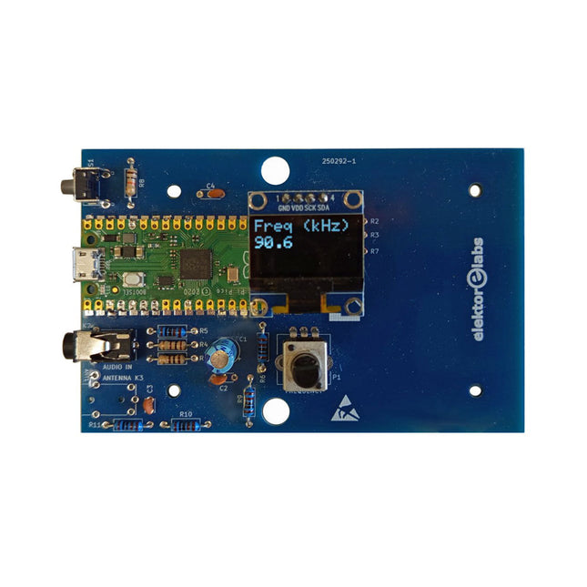
The Elektor AM Transmitter Kit allows streaming audio to vintage AM radio receivers. Based on a Raspberry Pi Pico microcontroller module, the AM Transmitter can transmit on 32 frequencies in the AM band, from 500 kHz up to 1.6 MHz in 32 steps of approx. 35 kHz.
The frequency is selected with a potentiometer and shown on a 0.96" OLED display. A pushbutton allows toggles the transmitting mode between On and Off. The range of the transmitter depends on the antenna. The onboard antenna provides a range of a few centimeters, requiring the AM Transmitter to be placed close to or inside the radio. An external loop antenna (not included) can be connected to increase the range.
The Elektor AM Transmitter Kit comes as a kit of parts that you must solder to the board yourself.
Features
The board is compatible with a Hammond 1593N enclosure (not included).A 5 VDC power supply with micro-USB connector (e.g., an old phone charger) is needed to power the kit (not included). Current consumption is 100 mA.
The Arduino software (requiring Earle Philhower’s RP2040 Boards Package) for the Elektor AM Transmitter Kit plus more information is available at the Elektor Labs page of this project.
Component List
Resistors
R1, R4 = 100 Ω
R2, R3, R8 = 10 kΩ
R5, R6, R9, R10, R11 = 1 kΩ
R7 = optional (not included)
P1 = potentiometer 100 kΩ, linear
Capacitors
C1 = 22 µF 16V
C2, C4 = 10 nF
C3 = 150 pF
Miscellaneous
K1 = 4×1 pin socket
K2, K3 = 3.5 mm socket
Raspberry Pi Pico
pushbutton, angle mount
0.96" monochrome I²C OLED display
PCB 150292-1
This clear acrylic case is the official case for the HackRF One/Pro board. It can replace the standard black plastic case of the HackRF One/Pro.
Assembly Instructions
Use a guitar pick or spudger to extract the HackRF One/Pro circuit board from the black plastic case.
Insert one long screw into each corner of the bottom acrylic panel. Secure each long screw with a short (5 mm) spacer on the opposite side of the panel.
Place the HackRF One/Pro circuit board (facing up) on top of the bottom panel, fitting the ends of the long screws through the corner mounting holes of the circuit board.
Secure the circuit board with one long (6 mm) spacer in each corner.
Place the top acrylic panel on top of the circuit board, aligning the cutouts with the circuit board’s expansion headers.
Secure each corner with a short screw.
Note: Do not overtighten! Hand-tighten only at every step.
This complete Arduino Uno-based microcontroller programming course features a textbook, a component kit, hands-on projects, and a comprehensive online course with simulations. It is ideal for step-by-step learning of embedded systems programming with Arduino using a practical, hands-on approach.
A Practical Introduction to Embedded Systems with the Arduino Uno
This course is designed for people who are new to embedded systems and looking for a structured, example-driven way to get started.
A kit of parts comprising LEDs and resistors, switches, sensors and actuators, displays, a breadboard and wires, and more is included. These are used in the course to illustrate example applications.
No prior experience with Arduino or embedded development is required. Each section features hands-on examples and mini projects designed to reinforce key concepts and inspire deeper exploration. By the end of the course, you’ll be able not only to reproduce the examples but also to build on them with your own ideas and applications.
What Will You Learn?
Microcontroller programming with Arduino using the Uno R3 board
Working with Digital I/O, read buttons and encoders, control LEDs and relays
Read analog inputs, voltages, and analog sensors
Generating analog output signals and PWM
Use serial communication like UART, I²C and SPI to control displays and read digital sensors and SD cards
Managing time
Working with interrupts
Real-time sensor input and control via buttons, LEDs, and displays
Control actuators like relays and servo motors
Who Is It For?
Students and self-learners exploring embedded systems
Makers and IoT enthusiasts looking to improve their hardware skills
Educators and trainers seeking ready-to-teach material
What's Inside the Box?
Access to the full course on the Elektor Academy Pro Learning Platform
Uno R3 microcontroller board + USB cable
Book: Programming Microcontrollers in C/C++ Using Arduino
Downloadable project files for every module
Component Box:
2× LED, red, 5 mm
LED, green, 5 mm
3× Resistor, 470 Ω, 0.25 W
LDR
Potentiometer, 10 kΩ, linear
Pushbutton
Rotary encoder module
Relay module
DHT22 Humidity & Temperature Sensor
TM1637-compatible 4-digit 7-segment display
MPU-6050 IMU with headers
SSD1306-compatible I²C OLED display
Micro SD card adapter with header
Buzzer
SG90 Micro Servo
ILI9341-compatible SPI 240×320 TFT display
20× Jumper wires
Breadboard
All Programming Courses (and differences in content)
Course
Arduino
Raspberry Pi Pico with Arduino C/C++
ESP32 with Arduino C/C++
Raspberry Pi Pico with MicroPython
ESP32 with MicroPython
Online Course
Access to Arduino Course
Access to Pico with Arduino C/C++ Course
Access to ESP32 with Arduino C/C++ Course
Access to Pico with MicroPython Course
Access to ESP32 with MicroPython Course
Board
Uno R3
Raspberry Pi Pico
ESP32
Raspberry Pi Pico
ESP32
Book
Programming Microcontrollers in C/C++ Using Arduino
Programming Microcontrollers in C/C++ Using Arduino
Programming Microcontrollers in C/C++ Using Arduino
Programming Microcontrollers in MicroPython
Programming Microcontrollers in MicroPython
Kit
40-piece Component Box
40-piece Component Box
40-piece Component Box
40-piece Component Box
40-piece Component Box
All-in-One AI Learning and Development Platform for Edge Intelligence
This NVIDIA Jetson-based AI Starter Kit is a versatile platform for learning, development, and hands-on experimentation in Edge AI.
Designed for use with the NVIDIA Jetson Orin Nano, the kit combines an 11.6-inch IPS display, an 8-megapixel pan-tilt camera, and an AI voice interaction system.
It includes 30 functional modules and 38 carefully designed Python courses that progress from beginner to advanced level. The course content covers Python fundamentals, sensor technology, AI vision, and image recognition.
With step-by-step practical exercises ranging from basic programming to real-world computer vision applications, this kit provides an ideal platform for students, makers, developers, and anyone looking to explore artificial intelligence and edge computing.
Please note: The NVIDIA Jetson Orin Nano is not included.
Features
Designed for the NVIDIA Jetson Orin Nano
AI voice interaction module
8 MP camera with pan-tilt control
Supports object and face tracking
No soldering or complex wiring required
Built-in 11.6-inch IPS display
30 functional modules
38 step-by-step Python lessons
I²C, UART, and GPIO expansion interfaces
Portable carrying case included
Specifications
Main Processor
Jetson Orin Nano
Number of Sensors
30
Sensor Board Design
Integrated sensor board, no soldering or complex wiring required
Screen
11.6-inch IPS Screen
Screen Resolution
1366 x 768
Camera
IMX219 8MP
Expansion Interfaces
2x I²C, 1x UART, 1x IO D13, 1xIO D12
Programming Environment
Based on Python
Number of Tutorials
38 creative tutorials
Target Audience
Students, teachers, hardware enthusiasts
Application Scenarios
Ideal for learning AI programming, Jetson Orin Nano basics
Dimensions
300 x 200 x 100 mm
Module List
Module
Quantity
Temperature & Humidity Sensor
1 pcs
Button
4 pcs
Ultrasonic Ranging Sensor
1 pcs
Light Sensor
1 pcs
Linear Potentiometer
1 pcs
Buzzer
1 pcs
LCD
1 pcs
Infrared Remote
1 pcs
Relay
1 pcs
NFC
1 pcs
PIR Motion Sensor
1 pcs
Joystick
1 pcs
4-Digital Display
1 pcs
LED
1 pcs
Microphone
1 pcs
Speaker
1 pair
Vibration Motor
1 pcs
Touch Sensor
1 pcs
8x8 RGB Matrix
1 pcs
Atmospheric pressure sensor
1 pcs
Tilt Switch
1 pcs
Stepper Motor
1 pcs
Accelerometer & Gyro
1 pcs
Gas Sensor (MQ2)
1 pcs
Hall Sensor
1 pcs
Rotary Encoder
1 pcs
U-shaped photoelectric switch
1 pcs
NTC
1 pcs
Servo
2 pcs
Monocular camera
1 pcs
Included
1x Elecrow AI Starter Kit for Jetson Orin Nano
1x IR Remote Control
1x NFC Card
1x 128 GB SD Card
1x 40-pin GPIO Cable
2x 22-pin FPC Cable
2x 24-pin FPC Cable
1x Jetson DP & USB Adapter Board
Not included
NVIDIA Jetson Orin Nano
Downloads
Manual
Wiki
OpenClaw Install and Config Guide
,
by Clemens Valens
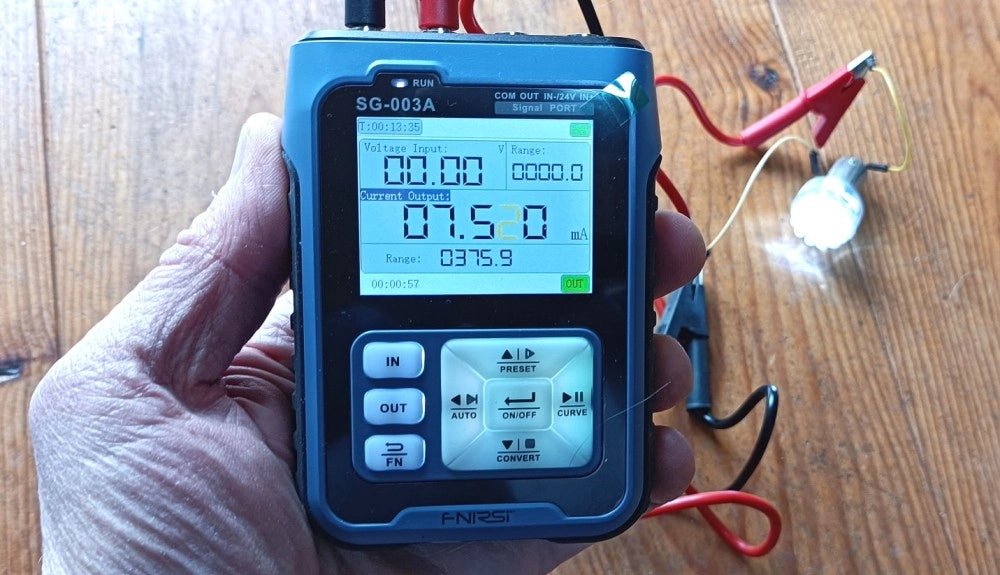
FNIRSI SG-003A Signal Generator
The FNIRSI SG-003A Multi-Functional Signal Generator is a kind of process meter for generating and measuring voltages, currents, and frequencies compatible with PLCs and other...