The Elektor Zener Diode Tester is essentially a constant-current source that can be switched in steps from 1 to 50 mA. It can be used to test Z-diodes up to a maximum of 54 V. Thanks to a 60-V step-up converter, the device can be powered by the usual 5 to 12 V.
The principle of this tester is straightforward. A Z-diode or other DUT (device under test, such as an LED) is biased by an adjustable current source. The voltage across the DUT can be measured with a multimeter. The voltage of most (small) Z-diodes is specified at a current of 5 mA. Depending on the application, the voltage at other currents can also be of interest. That is why six current settings are available: 1, 2, 5, 10, 20, and 50 mA. LEDs are often specified at a current of 20 mA.
What can be tested is:
Whether a Z-diode is defective (short circuit or high impedance).
Whether a Z-diode exhibits the correct Z-voltage.
How a Z-voltage changes with different currents.
What exact voltage is present at an integrated voltage reference.
Whether LEDs in a series chain differ in brightness (hence the 20 mA current).
What the current gain is for different base currents in (power) transistors.
The kit contains all parts listed in the bill of materials including PCB and enclosure.
Specifications
Supply voltage
5…12 V/2 A (USB-C)
Supply current (Itest = 50 mA)
1.1 A @ 5 V / 412 mA @ 12 V
Selectable currents
1, 2, 5, 10, 20, and 50 mA
Max. test voltage
>54 V @ Itest ≥1 mA
Max. output voltage
60 V @ Itest = 0 mA
Voltage limit at 5 V
4.5 V @ Itest = 1 mA / 5.18 V @ Itest = 50 mA
Enclosure dimensions
110 x 82 x 44 mm
PCB size
105.4 x 67.3 mm
Connections
4 mm banana sockets for multimeter
2 mm banana sockets for test clips
USB-C socket for power supply
Included
Resistors
R1 = 3.3 kΩ, 600 mW, 1%
R2 = 0.15 Ω, 1 W, 5%, LS 12.7 mm, ø 3.5 mm
R3, R8 = 180 Ω, 600 mW, 1%
R4, R6, R16 = 1 kΩ, 600 mW, 1%
R5, R19 = 47 kΩ, 600 mW, 1%
R7 = 3.9 kΩ, 1 W, 5%, LS 12.7 mm, ø 3.5 mm
R9, R10, R12 = 10 kΩ, 600 mW, 1%
R11, R13 = 100 Ω, 600 mW 1%
R14 = 249 Ω, 600 mW, 1%
R15 = 499 Ω, 600 mW, 1%
R17 = 2.49 kΩ, 250 mW, 1%
R18 = 4.99 kΩ, 250 mW, 1%
Capacitors
C1 = 470 uF / 35 V, 20%, Ir = 1.86 A, ø 12.5 mm, LS 5 mm, ESR = 0.038 Ω (Panasonic EEUTP1V471)
C2 = 1 uF / 100 V, 10%, X7R, LS 5 mm
C3 = 2.2 nF / 50 V, 10%, X7R, LS 5 mm
C4, C7 = 100 nF / 100 V, 10%, X7R, LS 5 mm
C5 = 100 uF / 100 V, 20%, ø 14 mm max., LS 5 mm
C6 = 1 nF / 100 V, 10%, X7R, LS 5 mm
Inductor
L1 = 100 uH, Irms = 2.4 A, Isat = 3.5 A, 0.09 Ω, radial, pitch 2.5/5/10 mm, ø 14 mm max. (Kemet SBC8-101-242)
Semiconductors
D1 = MUR120G, DO-41
D2, D4 = STPS3150RL, DO-201AD
D3 = Z-diode, 18 V, 1.3 W (BZX85C18)
D5 = Z-diode, 5.1 V, 0.5 W (1N5231B)
LED1 = LED in pushbutton S1
LED2 = LED, green, 3 mm
IC1 = MC34063, DIP-8
IC2 = LM4040BIZ-5.0/NOPB, TO-92 (TO-226AA-3)
IC3 = TL051CP, DIP-8
T1 = BC327.25, TO-92
T2 = STP40NF10L, TO-220
T3 = IRF9510PBF, TO-220
T4 = 2N7000, TO-92
Others
K1, K2, S1, S3 = 2-way screw terminal block, LS 3.5 mm, max. 1.5 mm²
connected to K1 = USB-C socket, 30 V/3 A, chassis mounted, wired, 9 x 16 mm
connected to K2 = Banana Connector, 2 mm, Socket, 60 VDC, Panel Mount, red (Multicomp 24.102.1)
connected to K2 = Banana Connector, 2 mm, Socket, 60 VDC, Panel Mount, black (Multicomp 24.102.2)
Test clip, red, 30 VAC/60 VDC (Hirschmann 931467101)
Test clip, black, 30 VAC/60 VDC (Hirschmann 931467100)
S1 = Pushbutton, panel mount, SPST-NO, 30 DC/100 mA, with red LED
S2 = Rotary Switch, 6 position, 2 pole, 30°, 250 V/150 mA
S3 = Toggle switch, panel mount, SPDT, solder lugs, 28 VDC
T2, T3 = Heat sink, 15°C/W, FK 214 SA-CB
Enclosure Hammond 1591XXSSBK, ABS, 110 x 82 x 44 mm
Knob for S2, round shaft 6 mm, ø 21 mm, with indicator line (Multicomp CP-LB21-6-6D)
4 x Self-tapping screw #4-1/4", carbon steel, pan head
Banana plug, red, 2 mm, 60 VDC (Multicomp 25.205.1)
Banana plug, black, 2 mm, 60 VDC (Multicomp 25.205.2)
Banana socket, black 4 mm, panel mount
Banana socket, red 4 mm, panel mount
for LED1, LED2 = Pin header, 1 x 2, vertical, pitch 2.54 mm
for LED1, LED2 = Pin socket, 1 x 2, vertical, pitch 2.54 mm
for T2, T3 = M3 screw, 10 mm, steel, pan head
2 x M3 washer, plain, steel
4 x M3 nut
for IC1, IC3 = DIP-8 socket
Wire, black, 0.25 mm² (24 AWG), stranded 14 x 0.15 mm, 1 m
Wire, red, 0.25 mm² (24 AWG), stranded 14 x 0.15 mm, 1 m
PCB 250772-1 v1.1
Links
Article
Elektor Labs
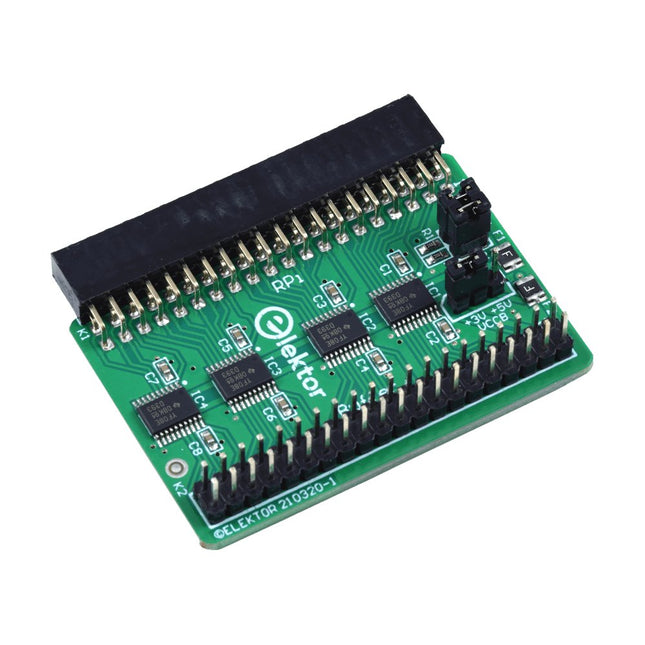
When you experiment with the Raspberry Pi on a regular basis and you connect a variety of external hardware to the GPIO port via the header you may well have caused some damage in the past. The Elektor Raspberry Pi Buffer Board is there to prevent this! The board is compatible with Raspberry Pi Zero, Zero 2 (W), 3, 4, 5, 400 and 500.
All 26 GPIOs are buffered with bi-directional voltage translators to protect the Raspberry Pi when experimenting with new circuits. The PCB is intended to be inserted in the back of Raspberry Pi 400/500. The connector to connect to the Raspberry Pi is a right angled 40-way receptacle (2x20). The PCB is only a fraction wider. A 40-way flat cable with appropriate 2x20 headers can be connected to the buffer output header to experiment for instance with a circuit on a breadboard or PCB.
The circuit uses 4x TXS0108E ICs by Texas Instruments. The PCB can also be put upright on a Raspberry Pi.
Downloads
Schematics
Layout
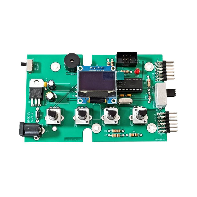
The Elektor Super Servo Tester can control servos and measure servo signals. It can test up to four servo channels at the same time.
The Super Servo Tester comes as a kit. All the parts required to assemble the Super Servo Tester are included in the kit. Assembling the kit requires basic soldering skills. The microcontroller is already programmed.
The Super Servo Tester features two operating modes: Control/Manual and Measure/Inputs.
In Control/Manual mode the Super Servo Tester generates control signals on its outputs for up to four servos or for the flight controller or ESC. The signals are controlled by the four potentiometers.
In Measure/Inputs the Super Servo Tester measures the servo signals connected to its inputs. These signals may come from for instance an ESC, a flight controller, or the receiver or another device. The signals are also routed to the outputs to control the servos or the flight controller or ESC. The results are shown on the display.
Specifications
Operating modes
Control/Manual & Measure/Inputs
Channels
3
Servo signal inputs
4
Servo signal outputs
4
Alarm
Buzzer & LED
Display
0.96' OLED (128 x 32 pixels)
Input voltage on K5
7-12 VDC
Input voltage on K1
5-7.5 VDC
Input current
30 mA (9 VDC on K5, nothing connected to K1 and K2)
Dimensions
113 x 66 x 25 mm
Weight
60 g
Included
Resistors (0.25 W)
R1, R3
1 kΩ, 5%
R2, R4, R5, R6, R7, R9, R10
10 kΩ, 5%
R8
22 Ω, 5%
P1, P2, P3, P4
10 kΩ, lin/B, vertical potentiometer
Capacitors
C1
100 µF 16 V
C2
10 µF 25 V
C3, C4, C7
100 nF
C5, C6
22 pF
Semiconductors
D1
1N5817
D2
LM385Z-2.5
D3
BZX79-C5V1
IC1
7805
IC2
ATmega328P-PU, programmed
LED1
LED, 3 mm, red
T1
2N7000
Miscellaneous
BUZ1
Piezo buzzer with oscillator
K1, K2
2-row, 12-way pinheader, 90°
K5
Barrel jack
K4
1-row, 4-way pin socket
K3
2-row, 6-way boxed pinheader
S1
Slide switch DPDT
S2
Slide switch SPDT
X1
Crystal, 16 MHz
28-way DIP socket for IC2
Elektor PCB
OLED display, 0.96', 128 x 32 pixels, 4-pin I²C interface
Links
Elektor Magazine
Elektor Labs
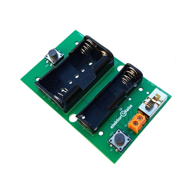
The Elektor Milliohmmeter Adapter uses the precision of a multimeter to measure very low resistance values. It is an adapter that converts a resistance into a voltage that can be measured with a standard multimeter.
The Elektor Milliohmmeter Adapter can measure resistances below 1 mΩ using a 4-wire (Kelvin) method. It is useful for locating short circuits on printed circuit boards (PCB).
The adapter features three measurement ranges – 1 mΩ, 10 mΩ, and 100 mΩ – selectable via a slide switch. It also includes onboard calibration resistors. The Elektor Milliohmmeter Adapter is powered by three 1.5 V AA batteries (not included).
Specifications
Measurement ranges
1 mΩ, 10 mΩ, 100 mΩ, 0.1%
Power supply
3x 1.5 V AA batteries (not included)
Dimensions
103 x 66 x 18 mm (compatible with Hammond 1593N-type enclosure, not included)
Special feature
On-board calibration resistors
Downloads
Documentation
Components are both shrinking and getting increasingly finer pitch year after year but your PCBs might have grown in size or the number of interconnected PCBs or the number of handsfree PCBite probes needed to test your design may have increased making it crowded on our other smaller base plates.
Features
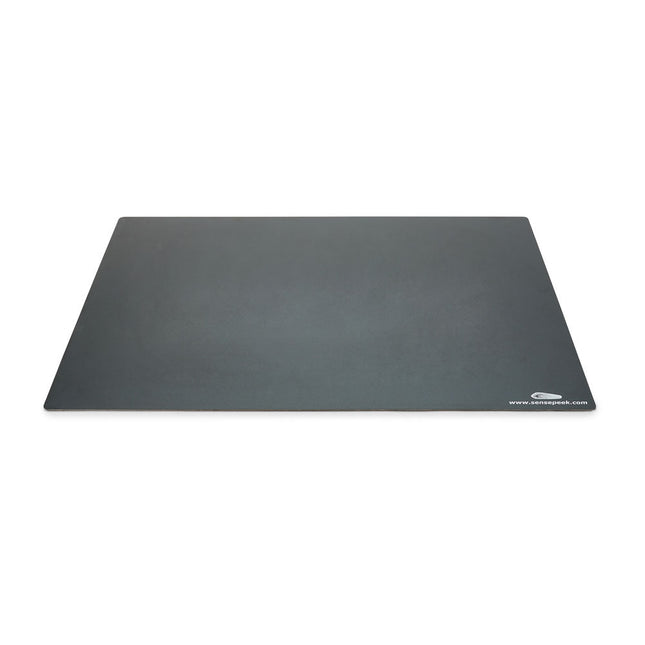
With a size of 297 x 420 mm (DIN A3) the extra large baseplate has room for most PCBs and many handsfree PCBite probes for those measurements sessions where more channels than available is needed.
So if you are looking for more space, extra protection or just want to clean up your work surface then this accessory is a perfect match.
Designed to be used with Sensepeeks magnetic PCBite line of products including PCB holders, hands free probes and magnifier.
Included
1x XL base plate (DIN A3) with pre-fitted insulation cover
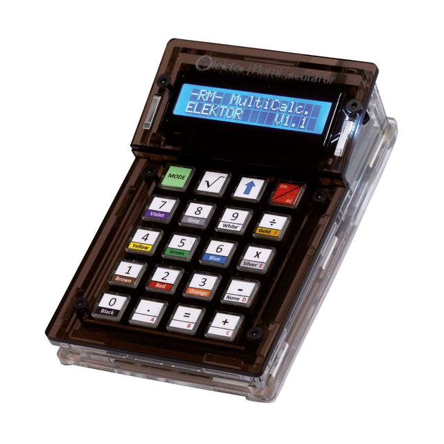
The Elektor MultiCalculator Kit is an Arduino-based multifunction calculator that goes beyond basic calculations. It offers 22 functions including light and temperature measurement, differential temperature analysis, and NEC IR remote control decoding. The Elektor MultiCalculator is a handy tool for use in your projects or for educational purposes.
The kit features a Pro Mini module as the computing unit. The PCB is easy to assemble using through-hole components. The enclosure consists of 11 acrylic panels and mounting materials for easy assembly. Additionally, the device is equipped with a 16x2 alphanumeric LCD, 20 buttons, and temperature sensors.
The Elektor MultiCalculator is programmable with the Arduino IDE through a 6-way PCB header. The available software is bilingual (English and Dutch). The calculator can be programmed with a programming adapter, and it is powered through USB-C.
Modes of Operation
Calculator
4-Ring Resistor Code
5-Ring Resistor Code
Decimal to Hexadecimal and Character (ASCII) conversion
Hexadecimal to Decimal and Character (ASCII) conversion
Decimal to Binary and Character (ASCII) conversion
Binary to Decimal and Hexadecimal conversion
Hz, nF, capacitive reactance (XC) calculation
Hz, µH, inductive reactance (XL) calculation
Resistance calculation of two resistors connected in parallel
Resistance calculation of two resistors connected in series
Calculation of unknown parallel resistor
Temperature measurement
Differential temperature measurement T1&T2 and Delta (δ)
Light measurement
Stopwatch with lap time function
Item counter
NEC IR remote control decoding
AWG conversion (American Wire Gauge)
Rolling Dice
Personalize startup message
Temperature calibration
Specifications
Menu languages: English, Dutch
Dimensions: 92 x 138 x 40 mm
Build time: approx. 5 hours
Included
PCB and though-hole components
Precut acrylic sheets with all mechanical parts
Pro Mini microcontroller module (ATmega328/5 V/16 MHz)
Programming adapter
Waterproof temperature sensors
USB-C cable
Downloads
Software
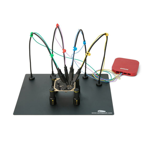
The SQ series of handsfree PCBite probes from Sensepeek are insulated, come with included color-coded cable holders and have a lower point of gravity making them even more stable compared with the original SP series of probes. All the loved features of handsfree measurement, exchangeable fine pitch spring tipped test needle and the minimalistic design is maintained to make traditional sized and handheld probes obsolete.
Features
All handsfree probes from Sensepeek makes instant measurements or long triggering sessions a breeze.
No more soldering wires to connect your probe or complicated tools to setup, just positioning the probe needle on any test point or component in the signal path and release.
Saves time and frustration during development, verification and repairs.
The minimalist design and the spring-loaded test needle makes it possible to simultaneously measure on fine pitch components and nearby signals.
Both length and weight of the SQ probes are perfectly balanced to be used with the included PCB holders and base plate which is a must for handsfree function.
The probe holder comes with a powerful magnet in the base, as for all PCBite probes and holders which makes the probe easy to place and reposition.
The SQ series of probes can be used handheld without the probe holder as they have an insulated grip but their full potential is used when measuring handsfree.
One side of the included baseplate is matte and the other is mirror polished. The mirror polished surface makes it easy to see components on the circuit board underside. For added protection during measurement the included insulation cover can be mounted on one of the surfaces.
Included
4x PCBite PCB holders
1x Set of yellow insulation washers for the PCB holders
1x Large Base plate (A4)
1x Insulation cover for the base plate (A4)
1x Micro fiber cloth
4x SQ10 probes and pin tipped test needles (black)
2x Banana to dupont test wires (red/black)
5x Dupont to dupont test wires
1x Set of cable holders (4 colors)
4x Extra test needles
Downloads
User guide (PCBite kit)
User guide (SQ10 probes)
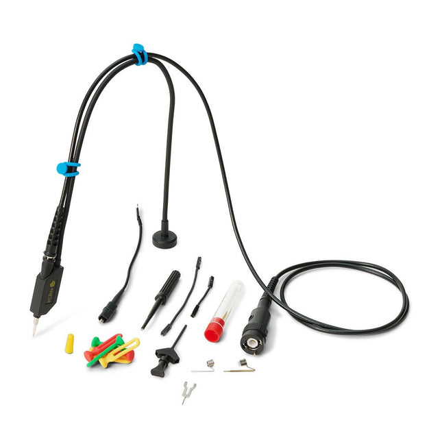
The SQ series of handsfree probes from Sensepeek have a lower point of gravity making them even more stable compared with the original SP series of handsfree probes. All probes in the SQ series are also insulated and can be used handheld as any traditional probe but their full potential is used when measuring handsfree.
The SQ series of oscilloscope probes also includes more ground options, have probe tip protection, longer cable and support for oscilloscopes with automatic scaling (10:1).
All the loved features of handsfree measurement, exchangeable fine pitch spring tipped test needle, color-coded cable holders and the minimalistic design is maintained to make traditional sized and handheld probes obsolete.
Both length and weight of the SQ probes are perfectly balanced to be used with PCBite PCB holders and base plate which is a must for handsfree function.
Features
Passive 10:1 probe with support for oscilloscopes with automatic scaling
Spring-loaded test needle for fine pitch measurements
Multiple ground options
Color coded cable holders
Probe tip protection
Insulated, can be used handheld
Improved probe holder for handsfree measurement when used with PCBite PCB holders
Included
1x SQ350 350 MHz probe with spring tipped test needle
1x SQ probe holder for handsfree measurement
1x Testhook with detachable cables (5 cm & 10 cm) for convenient ground connection
1x Alligator cable for convenient ground connection
1x Standard ground spring, for handheld measurements at rated bandwidth
1x Unique ground spring, for total handsfree measurements at rated bandwidth
1x Set of color coded cable holders (4 colors)
1x Probe tip protection
1x Extra test needle
Downloads
User Guide SQXX0 Rev1.1
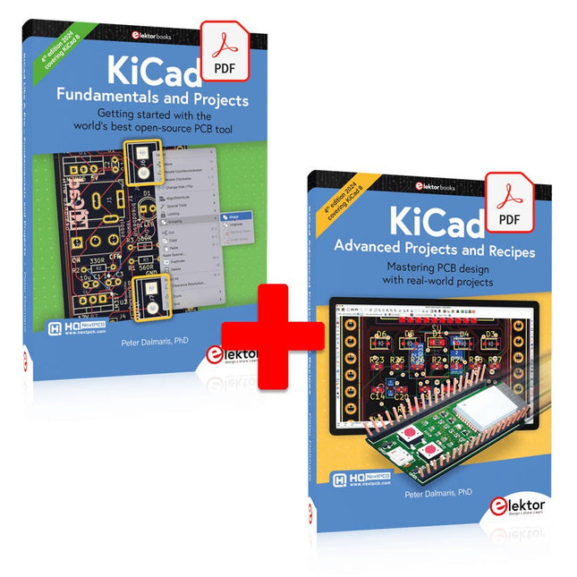
This bundle includes both volumes of "KiCad Like a Pro" (4th edition 2024). In Fundamentals and Projects (normal price: €39.95), you'll learn how to use KiCad through a practical approach, helping you quickly become productive and start designing your own boards. Advanced Projects and Recipes (normal price: €34.95) allows you to practice your new KiCad skills by challenging yourself with a series of real-world projects.
The latest iteration of KiCad, the world’s best free-to-use Printed Circuit Board tool, is packed with features usually found only in expensive commercial CAD tools. This modern, cross-platform application suite built around schematic and design editors, with auxiliary applications is a stable and mature PCB tool. KiCad 8 is a perfect fit for electronic engineers and makers.
Here are the most significant improvements and features in KiCad 8, both over and under the hood:
Modern user interface, completely redesigned from earlier versions
Improved and customizable electrical and design rule checkers
Theme editor allowing you to customize KiCad on your screen
Ability to import projects from Eagle, CADSTART, and more
Python scripting API
Improved integrated SPICE circuit simulator
Multi-sheet schematics
Filters define selectable elements
Enhanced interactive router helps you draw single tracks and differential pairs with precision
New or enhanced tools to draw tracks, measure distances, tune track lengths, etc.
Advanced interactive router
Built-in bill of materials generator
Realistic ray-tracing capable 3D viewer
Customizable teardrops
Plug-in manager for quick installation of themes, libraries and functionalities such as autorouters and BOM generators
The first book KiCad Like A Pro – Fundamentals and Projects will teach you to use KiCad through a practical approach. It will help you become productive quickly and start designing your own boards. Example projects illustrate the basic features of KiCad, even if you have no prior knowledge of PCB design. The author describes the entire workflow from schematic entry to the intricacies of finalizing the files for PCB production and offers sound guidance on the process.
The second book KiCad Like A Pro – Advanced Projects and Recipes will help you to practice your new KiCad skills by challenging you in a series of real-world projects. The projects are supported by a comprehensive set of recipes with detailed instructions on how to achieve a variety of simple and complex tasks. Design the PCBs for a solar power supply, an LED matrix array, an Arduino-powered datalogger, and a custom ESP32 board. Understand the finer details of the interactive router, how to manage KiCad project teams with Git, how to use an autorouter on 2 and 4-layer PCBs, and much more.
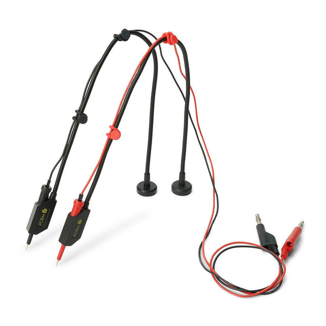
The SQ series of handsfree PCBite probes from Sensepeek are insulated, come with included color-coded cable holders and have a lower point of gravity making them even more stable compared with the original SP series of probes. All the loved features of handsfree measurement, exchangeable fine pitch spring tipped test needle and the minimalistic design is maintained to make traditional sized and handheld probes obsolete.
Features
All handsfree probes from Sensepeek makes instant measurements or long triggering sessions a breeze.
No more soldering wires to connect your probe or complicated tools to setup, just positioning the probe needle on any test point or component in the signal path and release.
Saves time and frustration during development, verification and repairs. The minimalist design and the spring-loaded test needle makes it possible to simultaneously measure on fine pitch components and nearby signals.
Both length and weight of the SQ probes are perfectly balanced to be used with PCBite PCB holders and base plate which is a must for handsfree function.
The probe holder comes with a powerful magnet in the base, as for all PCBite probes and holders which makes the probe easy to place and reposition.
The SQ series of probes can be used handheld without the probe holder as they have an insulated grip but their full potential is used when measuring handsfree.
Included
2x SQ10 probes and pin tipped test needles (red/black)
2x Banana to dupont test wires (red/black)
1x Set of cable holders (red/black)
2x Extra test needles
Downloads
User guide
,
by Clemens Valens
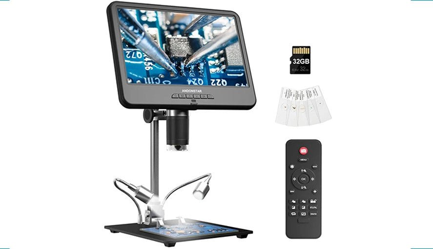
Explore the Tiny World: Andonstar AD210 Digital Microscope in Focus
The Andonstar AD210 offers an accessible entry point into the world of digital microscopy with its expansive 10.1" display. Designed primarily for electronics labs, this...
,
by Lobna Belarbi
Kickstart Your Electronics Journey with Elektor’s Learning Collection
Whether you're new to electronics or aiming to level up your embedded skills, Elektor’s Learning Collection delivers expert-curated kits, courses, and hands-on bundles. The first...